Booth & Co AXBRIDGE BC-AXB-149/RRK-CP User manual
AXBRIDGE
BC-AXB-149/RRK-CP
BC-AXB-149/RRK-BN
INSTALLATION GUIDE
This instruction booklet covers model:
BC-AXB-149/RRK-CP
BC-AXB-149/RRK-BN
Version 1, 1-5-19
VADO
Wedmore Road, Cheddar,
Somerset, England BS27 3EB
tel 01934 744466
fax 01934 744345
www.vado.com
sales@vado.com
23
Please read these instructions carefully before starting installation and keep for
future reference.
Remove all packaging and check the product for missing parts or damage before
starting installation.
Any alterations made to this product and fittings may infringe water regulations and
will invalidate the guarantee.
The installation must comply with all Local/National Water Supply Authority
Regulations/Byelaws and Building and Plumbing Regulations.
To be installed in accordance with BS EN806.
We strongly recommend that you use a qualified and registered plumber.
General installation
Important - please read
This fitting is a mixing device and therefore water supplies should be reasonably
balanced.
When installed, the fitting must comply with the requirements of the Water Supply
(Water Fittings) Regulations 1999 and Scottish Byelaws 2004.
For further information, contact the Water Regulations department of your local water
supplier (see the WRAS website www.wras.co.uk for details) or the Water Regulations
Advisory Scheme by email (info@wras.co.uk) or telephone: 01495848454.
Before making any inlet pipe connections, all supply pipes MUST be thoroughly flushed
to remove debris. Failure to do so could result in damage or low flow from the mixer
unit. Water Supply (Water Fittings) Regulations 1999 Schedule 2 Section 13.
The fitting of isolating valves to the inlet feeds is advised for ease of maintenance.
Please take great care when installing this mixer not to damage its surface.
Please note if installing in an enclosed environment, access should be left for servicing
and maintenance. No costs relating to inadequate access can be accepted.
Operating Specifications
Operating Pressure
Minimum operating pressure 1 bar
Maximum operating pressure 5 bar
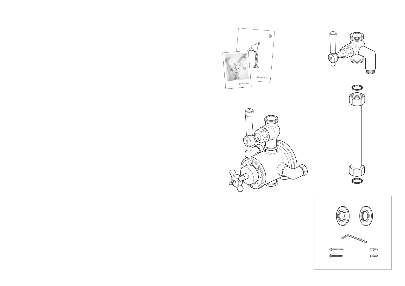
Contents of Packaging
Installation guide &
User manual
Covers
AX BR ID GE
BC- A XB -14 9- CP
BC- A XB -14 9- BN
INS TA LL A TI ON G UI DE
SH OWER V ALVE W ITH RI SER
US ER GUID E
KE EP FOR
FU TU R E R E FE R E N C E
AX B RI DG E
Accessory box 1
Diverter
Screws x 2 Wall plugs x 2
Hex key
Short riser with 2 washers
Valve body
4 5
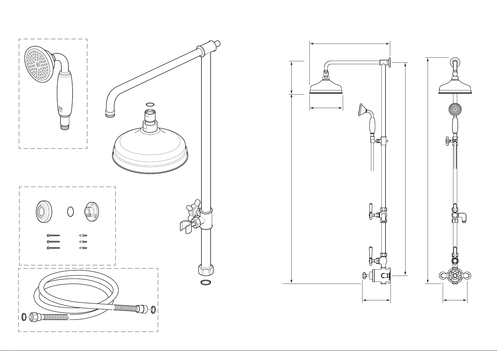
Contents of Packaging
Handset
Riser with washer
Shower hose with 2 washers
Shower head with washer
Cover O-ring Bracket
Accessory box 2
Screws
x 2
Wall plugs
x 2
Dimensions
495mm
205mm
170mm 150mm
921mm 202mm
1070mm
1143mm
6 7
Installation - Quick guide
2
3
1
4
5 6
1
2 3
4
0 5
1
2 3
4
0 5
1
2 3
4
0 5
1
2 3
4
0 5
147-153mm
x 3
Installation - Quick guide
9
10
8
6mm
1
2
3
5
1
2
3
5
4
7

8 9
Installation - Quick guide
11 12
1413
Installation - Quick guide
15 16
19 20
1817

10 11
Installation - Quick guide
21 22
23 24
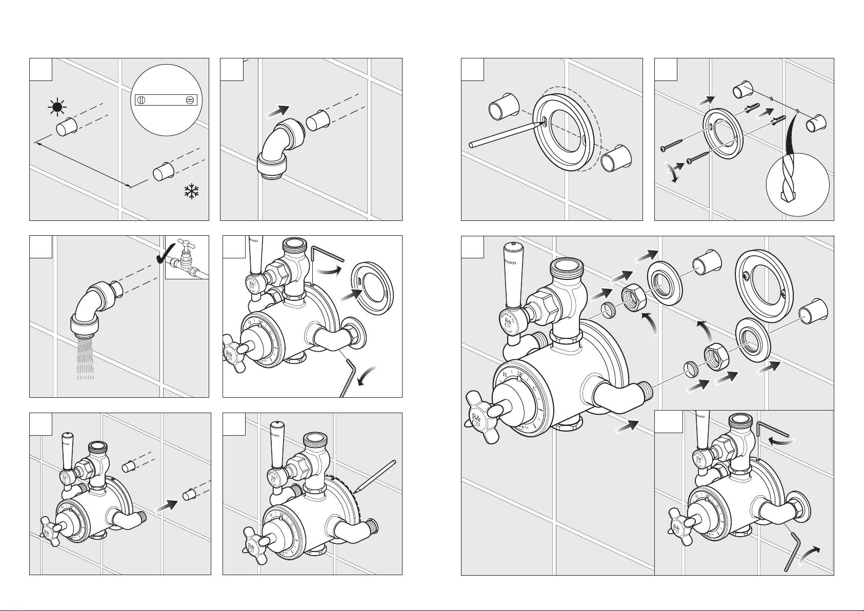
Installation
Prepare the wall with 2 copper pipes
at 147-153mm centres. Make sure the
pipes are level.
Connect the water supply to the
inlet pipes. The hot water should be
connected to the left hand pipe .
Before installing your new mixer, flush
through the pipe work to ensure removal
of debris, turn off the water supply.
(Do not allow dirt, metal particles or
shavings to block the filters fitted on
inlets).
147-153mm
Mounting plate
Inlet pipe
20-25mm hole
Remove the mounting plate from the
back of the valve by releasing the three
grub screws and pulling out the plate.
Place the mounting plate in the centre
of the marked position and mark the two
fixing holes.
Temporarily place the valve over the
copper pipes and mark the back of the
body against the wall.
There is a small amount of adjustment
on the inlet pipes to allow fitting onto the
copper pipes. Screw each side in or out
as required, ensuring that both sides are
screwed in equally.
Remove the valve.

12 13
Installation
Fig. 1
Cover
Cold
Hot
During and after installation protect the outer parts of the valve to avoid damage to
plated surfaces.
Place the covers over the copper pipes, followed by the nuts and the olives.
Push the valve onto the copper pipes and the mounting plate, tighten both the nuts on
the inlets being careful not to damage the plated surface.
Drill the marked holes to a suitable
depth for the wall plugs and secure with
supplied screws.
If you are fitting the valve to a partition
wall or a wall of particularly soft
substrate you will need specialist fixings.
Mounting plate
Screws
Wall plugs
Nut
Olive
Inlet pipe
Installation
Secure the valve into position by
tightening the three grubs crews, one
at 12 o'clock and the other two at 4 and
eight o'clock
Hex key
Place the washer into the nut and screw
the short riser to the diverter and tighten
being careful not to damage the chrome
surface.
Grub screw
Short
riser
Washer
Diverter
Hose
connection
Hex key

14 15
Installation - riser rail
Place the washer into the nut and screw
the top riser to the diverter and tighten
being careful not to damage the chrome
surface.
Slide the wall bracket onto the riser and
place against the wall.
Wall bracket
Riser
Valve
Washer
Short
riser
Riser
Washer
Diverter
Short riser
Place the washer into the nut on the
bottom of the short riser and screw onto
the valve.
Do not over tighten.
Installation
Warning! Please check for any
hidden cables and pipes before drilling
holes in the wall.
Drill the marked holes to a suitable
depth for the wall plugs and secure with
supplied screws.
Slide on the cover.
Replace the riser onto the valve.
Slide the riser into the wall bracket.
Make sure that the riser is vertical and
secure in position using the grub screw
on the side of the wall bracket.
Finally tighten the nut to secure the riser
to the valve.
Make sure that the riser is vertical and
mark the 3 fixing holes in the wall bracket
with a pencil.
Wall bracket
Wall bracket
Screws
Wall plugs
Cover
Wall bracket
Riser
Hex key

16 17
Washer
Hose
Diverter
Handset
Installation - Shower hose
Washer
Hose
Shower head
Washer
Riser arm
Shower head
Make sure there is a rubber washer in
place in the shower head and screw onto
the riser arm.
Handset
Place one of the rubber washer into the
cone end of the hose and screw to the
handset.
Valve
Place the second rubber washer into the
nut end of the hose and attach it to the
diverter outlet.
Commissioning
The valve has been factory set under
balanced pressures and hot supply at 65°C.
When your specific operating conditions are
significantly different from the above, the
temperature of the delivered water may vary
from the setting.
When the difference is too great, you can
adjust the calibration of the valve to suit
individual requirements of the installation.
Note: mixed water temperature at the
terminal fitting should not exceed 46°C.
With the temperature handle fitted and the
temperature indicator located at
12 o'clock, check the temperature of the
water being delivered from the outlet with a
thermometer.
Note: temperature readings should be
taken at normal flow rate after allowing the
system to stabilise.
If the temperature is not 38°C proceed to
commission the valve as follows.
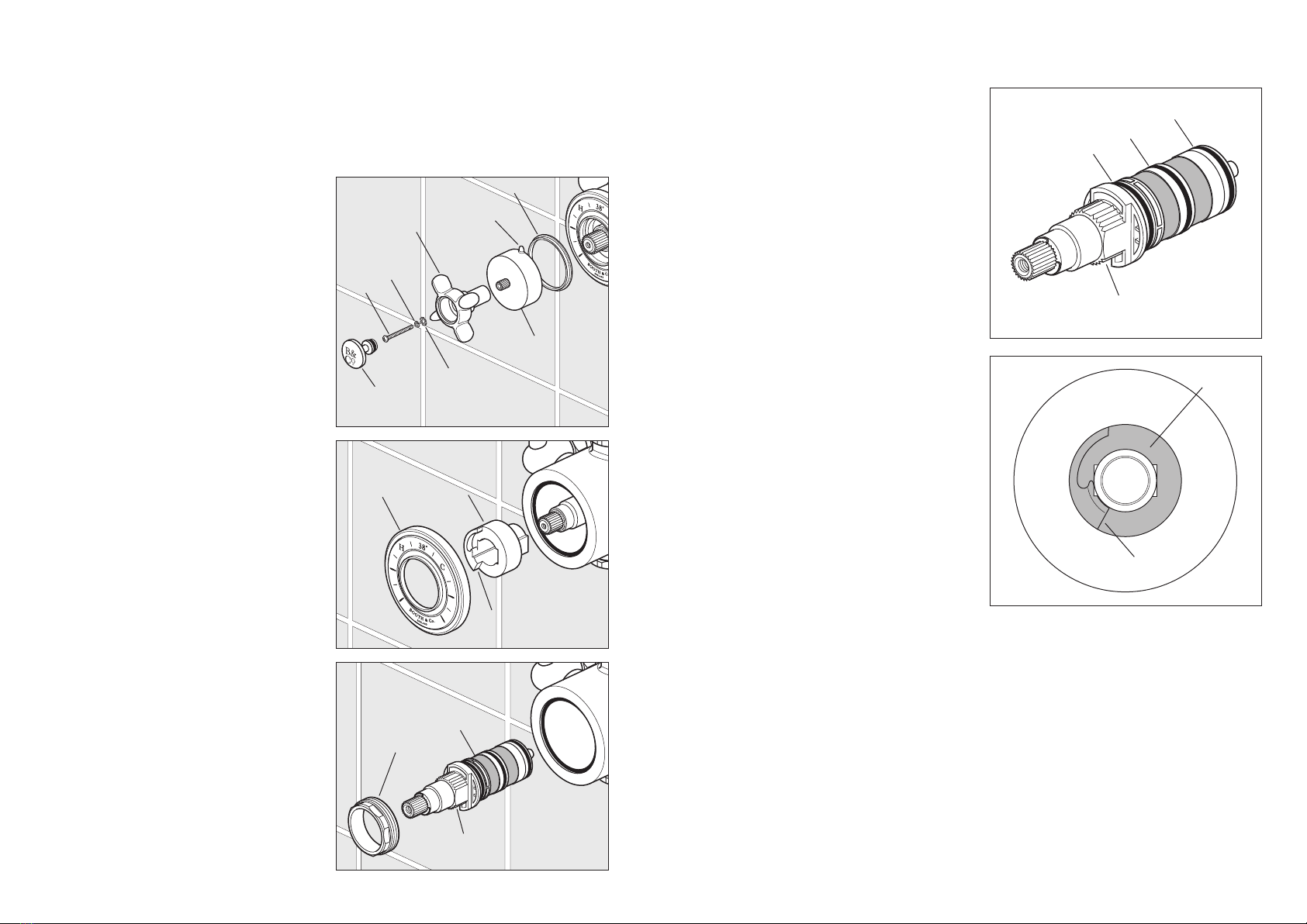
Carefully prise out the ceramic screw cover
with a suitable flat tool, remove the screw
and washers and pull off the handle, shroud
and spacer ring (g 1).
Ensure the step on the stop ring is as
pictured (g 2).
Rotate the spline of the thermostatic
cartridge clockwise to decrease and anti-
clockwise to increase the temperature until
38°C is achieved at the outlet (g 3).
Note: the sensing part of the thermometer
probe must be fully submerged in the water
that is to be tested.
Carefully replace the spacer ring, shroud
and temperature handle with the
temperature indicator located at 12
o'clock without turning the spline of the
thermostatic cartridge.
Screw the temperature handle in place
using the washers and screw, replace the
screw cover.
Ensure the water temperature does not
exceed 46°C when turned entirely
anti-clockwise.
Fig. 2
Fig. 3
Stop ring
Spline
Handle
Screw
cover
Lock
washer
Screw
Spring
washer
Shroud
Spacer ring
Indicator
Fig. 1
Step
18 19
Maintenance
We advise that the below is carried out annually as failure to do so may result in
invalidation of warranty.
Shut off the water supply to both hot and cold inlets, before commencing any
maintenance work below.
Fig. 1
Fig. 2
Fig. 3
Handle
Screw
cover
Lock
washer
Screw
Spring
washer
Shroud
Temperature
ring
Securing nut
Stop ring
Cartridge
Step
Locating slot
Spacer ring
Indicator
Thermostatic cartridge
To clean the filters, you must first remove
the cartridge from the housing.
Removing the Cartridge
1. Shut off the water supply to both inlets.
Ensure the thermostatic valve has been
successfully isolated.
2. Using a suitably flat tool remove the
screw cover, unscrew and remove the
temperature handle and pull off the shroud
and spacer ring (g 1). Remove the ceramic/
chrome temperature ring allowing access to
the valve (g 2).
3. Using pliers if required gently remove
temperature stop ring (essential) (g 2).
4. Turn shower on to check isolation, please
ensure that your body/hands are not under
the flow of water as there is a potential for
delivery of hot water.
5. Using a 32mm box spanner unscrew and
remove the valve securing nut then carefully
pull out the thermostatic cartridge (g 3).
Note: Ensure care is taken as a small
amount of residual water may escape when
removing the cartridge.
Fig. 5
Fig. 4
Maintenance
6. Clean the cartridge filters by rinsing
them under running water to remove any
debris.
7. If there is limescale deposits then it is
recommended to immerse the cartridge
for a few minutes in 50% white vinegar
+ 50% hot water, brush the filters gently
and then rinse under running water to
clean all particles. If this is not effective, a
replacement cartridge should be fitted.
8. Before reassembling the cartridge,
clean its housing with a wet cloth and
grease the O-rings using a suitable
silicone grease. Insert the thermostatic
cartridge into the body aligning the slot in
the body with the grub screw (g 4).
9. Screw the securing nut on and tighten
using a box spanner, careful not to
overtighten.
10. Replace the temperature stop ring on
the cartridge with the cold step located at
7 o’clock (g 5).
11. Turn the water supply on.
12. Check the water temperature to
ensure correct commissioning. See
previous section.
13. Replace the ceramic/chrome
temperature ring, spacer ring and shroud
with the temperature indicator located at
12 o'clock without turning the spline of
the thermostatic cartridge.
Screw the temperature handle in place
using the washers and screw, replace the
screw cover.
O-ring
Locating slot
O-ring
O-ring
Stop ring
Step
This manual suits for next models
1
Table of contents
Other Booth & Co Bathroom Fixture manuals


Popular Bathroom Fixture manuals by other brands

Glacier bay
Glacier bay 67778-0001 Installation and care guide

VINNOVA
VINNOVA 703472 manual

Hans Grohe
Hans Grohe AXOR Starck 10925000 Instructions for use/assembly instructions

noken
noken SKY Installation and Maintenance

Hans Grohe
Hans Grohe Fixfit Square 26455000 Assembly instructions

Signature Hardware
Signature Hardware Contemporary 949170 quick start guide

Orbital Systems
Orbital Systems R3 OS8733-E manual

KEUCO
KEUCO Axess 35006 010801 Mounting instruction

Hans Grohe
Hans Grohe MySelect S Vario 26637400 Assembly instructions

Relax
Relax Smart 0801-A Assembly instructions

Kinedo
Kinedo Eden installation instructions

Blanke
Blanke BAY-BOX S Installation instruction


