Steamist TSG-7 User manual
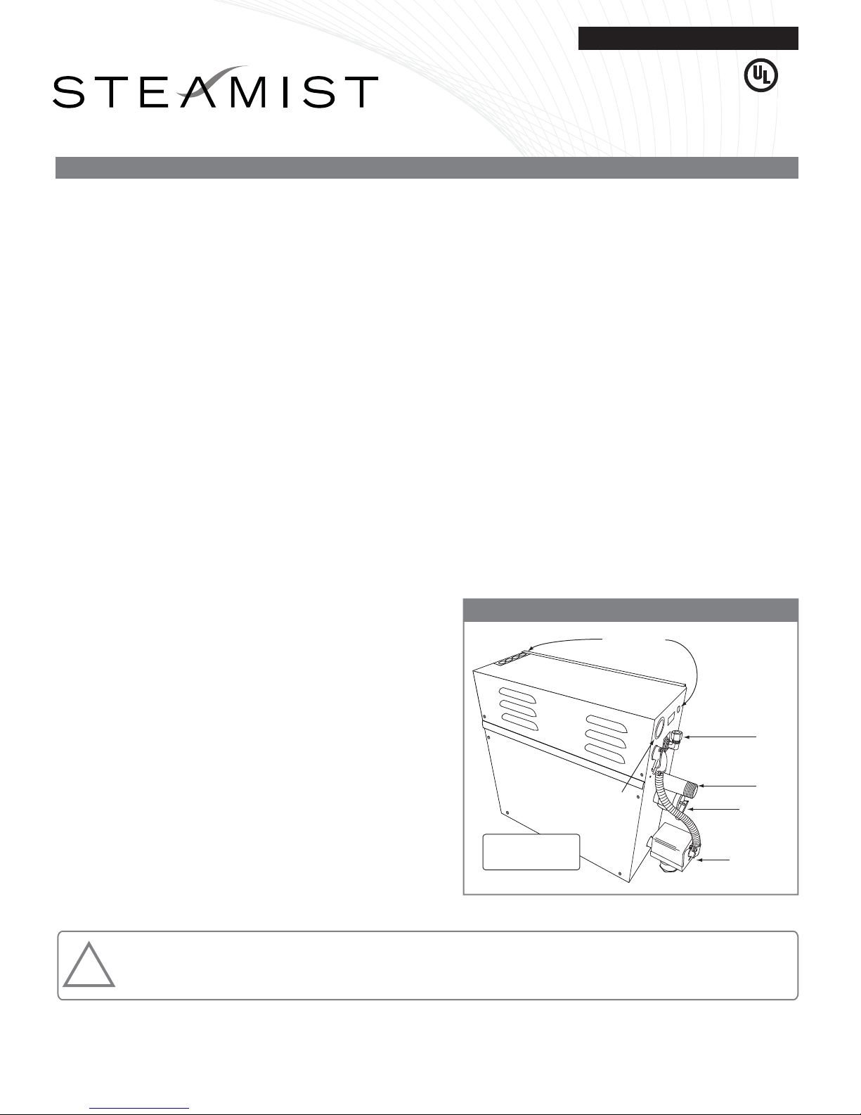
Optional Auto
Drain Valve
Model TSG-AD
Water Inlet
⅜" Compression
Fitting
¾" Safety
Relief Valve
¾" Steam
Outlet
Knockouts for
Electrical Supply Line
Knockouts for
Control Cable
Install Upright
and Level
IMPORTANT: The warranty of this product is voided if it is used in a commercial application or for anything other than a residential
steambath installation. This product is not intended for use with Home Automation systems.
Plumbing Installation Instructions
Steambath Generator Models: TSG-7 and TSG-10
The Steamist “TSG” Generator comes factory assembled,
carefully wired and tested.
WARNING: All electrical power should be turned OFF when
working with Steam Generator.
IMPORTANT: The Plumbing Installation must conform to local
and national codes.
1. Pre-Installation
a) Be sure that the proper size Steam Generator has been
selected by using the sizing page in the “Full Line
Brochure,” “Pricing Guide,” “The Generator Sizing
Guide,” “Architectural Guidelines,” or in the Residential
Systems/Steambath Product Information section of the
Steamist website - www.steamist.com.
CAUTION: An improperly sized Steam Generator may
NOT produce the amount of steam necessary to reach
selected temperature.
b) The Steam Generator should be located as close as
possible to the Steamroom/Shower or tub enclosure.
Steam pipe should NOT exceed twenty-five feet in length.
If the steam pipe exceeds ten feet, use an appropriate
pipe insulation rated for a minimum of 212°F. Possible
locations include Vanity, Closets, or Basement near bath
area. The serial number plate should be visible and the
Steam Generator should be accessible for service. Refer
to Installation Suggestions on page 4. Do NOT install
Generator outdoors, in an attic, in a moist, humid area, or
in an area where parts may freeze or corrode. Also, do
NOT install near flammable materials such as paints,
thinners, gasoline, etc.
c) The steam line and safety valve reach a temperature of
212°F during operation and should be appropriately
protected to prevent personal injury by accidental
contact.
2. Plumbing Rough-in
Plumbing rough-in is required for the water supply and
steam line; this should be completed before the walls
are closed. For operation, the “TSG” Steam Generator
requires a ⅜" O.D. copper tubing to the fitting on the
generator for water inlet and a ¾" copper or brass pipe
for steam outlet.
NOTE: Safety Valve should be connected to a minimum ¾"
indirect waste or as required by local plumbing codes. In
the unlikely event this valve should open, the discharge
must be directed to prevent damage to the home.
a) Water Inlet - Rough in a water line, 120 PSI max,
to the hot or cold supply. A shut off valve with a
3/8” connection to the steam generator is to be
provided at the generator location (see Figure 4 on
page 3).
b) Steam Outlet - Rough in the steam line using a
minimum of a ¾" copper or brass pipe; do NOT
use black iron or galvanized pipe; it will rust and
discolor the wall of the steambath. Do NOT use
any plastic type pipe or fittings. The steamhead
location should be 18" above the shower floor or 6"
above the rim of the bathtub, as far from the
seating area as possible.
CAUTION: No shutoff valve can be installed in the steam
line. Do NOT create traps or valleys in this line which would
trap condensation and block the flow of steam. The steam
pipe should be pitched allowing condensation to run back
toward the Steam Generator (preferred), or toward the
steamhead. When installing multiple steam generators DO
NOT interconnect the steam pipes.
Figure 1 - Steam Generator
CUS
®
05/11 Pub. No. 203-E
- 1 -
WARNING: Elderly persons, pregnant women, or those suffering from heart disease, high blood pressure, diabetes, or
who are otherwise not in good health, do not use this device unless directed to do so by a physician. Also, do not use
steambath while under the influence of alcohol. For additional Important Safety Information, please see a separate
instruction Pub. No. 199.
!
®
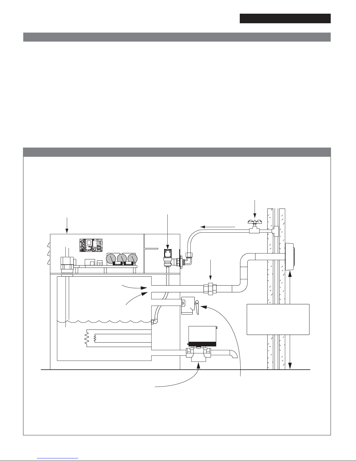
Steam
Generator
Shutoff Valve
Electric Water
Solenoid Valve Cold Incoming
Water Supply
120 PSI Max
Tank
Steam Line
IMPORTANT: Install
steamhead 18" above the
shower floor or 6" above
the rim of the bathtub.
Union
(Required)
Water
Level
Probe
Pressure Safety Valve
Connect to indirect waste or as
required by local codes.
Optional Auto Drain Valve
Connect to indirect waste or as
required by local codes.
Plumbing Installation Instructions
3. Steam Generator Installation
The Steam Generator should be mounted in a location conve-
nient for hook-up and service by the plumber and electrician.
CAUTION: The Steam Generator is designed to be used
ONLY in an upright and level position; to do otherwise would
damage the unit and void the warranty.
a) The Steam Generator can be mounted to a wall or
set on the floor. However, the unit must be secured.
To secure the unit to a vertical wall, loosen the two
screws holding the electrical access cover, remove
cover (see Figure 1). Located inside the cabinet
near the top left and right corners are mounting
holes. Place top cover back and secure.
Figure 2 - Plumbing Diagram
Installation Instructions Models: TSG-7 and TSG-10
05/11 Pub. No. 203-E
- 2 -
b) Connect the ⅜" water inlet to a shut off valve as
described in Section 2.a. The valve must be kept in
an open position during normal operation. In an area
where water hammer is a problem install a water
hammer arrestor in the line. Refer to Figure 2.
IMPORTANT: Do NOT use a “saddle valve” or
piercing type valve for water connection.
c) Connect the steam line from rough-in location
described in Section 2 to the ¾" nipple on the Steam
Generator using a union.
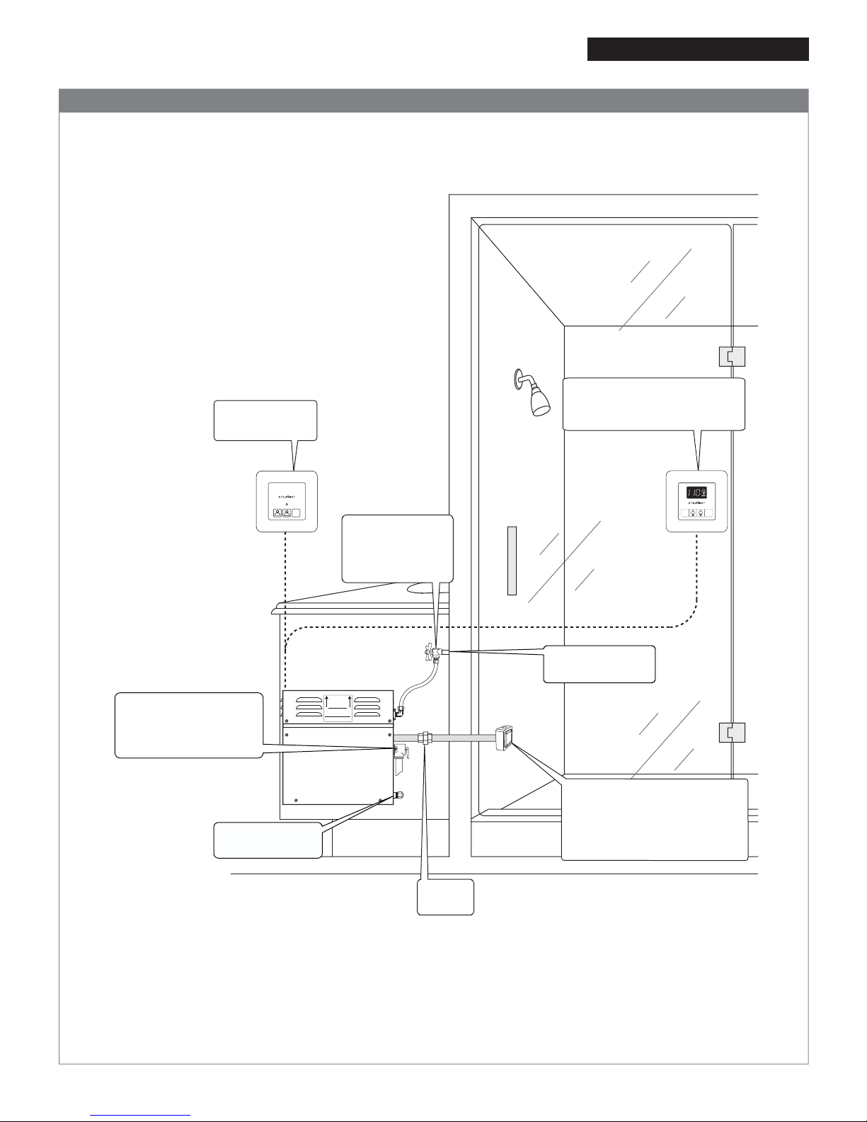
TSX-220 Auxilary
Outside Control
Steam Outlet Pipe - Use a minimum of a ¾" Copper or Brass pipe.
CAUTION: Do NOT install a shutoff valve on the steam outlet pipe. Do NOT create traps or valleys in this line which
would prevent the flow of steam. The steam outlet pipe should be pitched toward the Steam Generator (preferred),
allowing condensation to run back into the Steam Generator or toward the steamhead. If the steam pipe exceeds ten
feet, use an appropriate pipe insulation rated for a minimum of 212°F.
IMPORTANT:
INSTALLWITH ARROWS POINTING UP
WARNING: Unit must be installed
INDOORS,in a DRY,NON-FREEZING
location and with arrows pointing up.
Serviceby authrorized personnel only.
NOTE: Read all instructions before installation
CAUTION: Toprevent internal damage hold all fittings
securely while making plumbing connections.
NOTE: See Wiring Diagram on reverse side of cover.
CAUTION: Turn off electric before removing cover.
NOTE: This is NOT intended to be used for space
heatingpurposes. 009-1081
Slope ceiling 2" per foot
TSC, TSC-250, or TSC-350
Control MUST be installed
inside the Steam room.
Steamhead Installation
Steamhead should be mounted
18" above the finished floor or
6" above the rim of the tub as
far from the bather as possible.
Safety Valve
Connect ¾" pipe to an
indirect waste or as
required by local codes.
Union
Required
Auto Drain Ready
½" Capped Line
The Plumbing Instructions must be given to the homeowner for future use.
⅜" Shutoff Valve
Keep in open
position during
normal operation.
Connect to Hot or
Cold water supply
Plumbing Installation Instructions
Figure 4 - Typical Installation Models: TSG-7 and TSG-10
05/11 Pub. No. 203-E
- 3 -
STOP
2
12
1
TIME
TEMP
IM
STOP
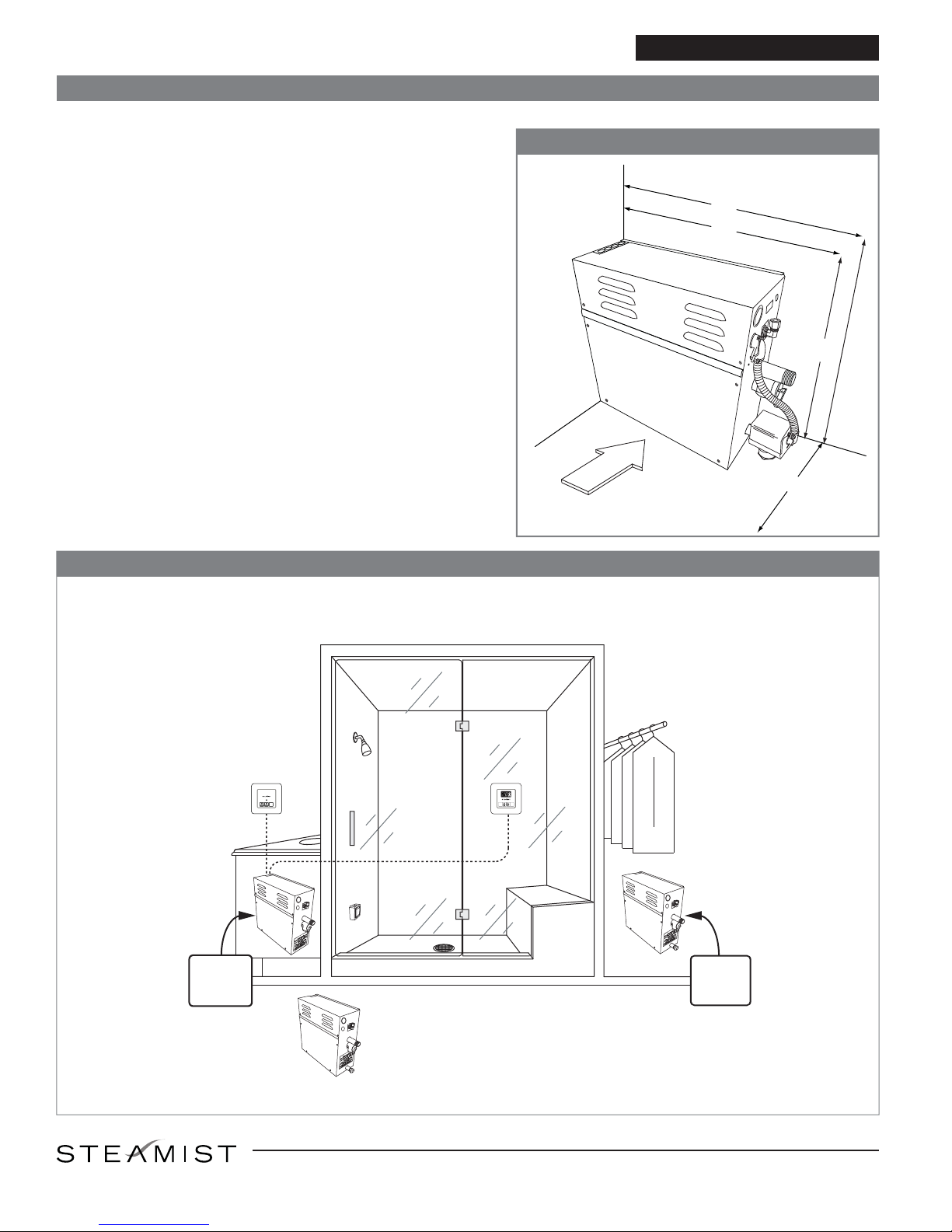
28"
21"
22"
18"
Access
Use 35" with
Optional Auto Drain
Plumbing Installation Instructions
Access Requirements Models: TSG-7 and TSG-10
05/11 Pub. No. 203-E
- 4 -
CAUTION: Do NOT install the steam generator in an attic location.
Select a location for mounting the Steam Generator that is
accessible for installation and service. The access requirement
indicates the minimum space for convenient access to Steam
Generator.
CAUTION: All models must be installed INDOORS, in a DRY,
NON-FREEZING location away from flammable materials such
as: Gasoline, Paints, Thinners, Etc.
IMPORTANT: Steam Generator must be installed upright and level.
Figure 5
Installation Suggestions
®
Alternate Basement Location
(Insulated and Dry)
STOP
2
12
1
TIME
TEMP
IM
STOP
Steam
Generator
in Vanity
Alternate
Closet
Location
East Coast Office: 25 E. Union Ave., East Rutherford, NJ 07073 • Tel: 800-577-6478 • Fax: 201-933-0746
West Coast Office: Tel: 800-355-6478 • Fax: 661-940-1617
Other manuals for TSG-7
1
This manual suits for next models
1
Other Steamist Iron manuals


