Steamist SM-5 User manual

Knockouts for
Electrical Supply Line
Water Inlet ⅜"
Compression
Fitting
¾" Steam
Outlet
¾" Safety
Relief Valve
Auto Drain Ready
½" Capped line
Identification
Plate
Knockouts for
Control Cables
Securing
Screws
Electric Panel
Cover
Install Upright
and Level
Knockouts for
Control Cables
®
The Steamist “SM” Generator operates with one or two controls
appropriately located inside and/or outside the steamroom. It’s
small enough in size to be tucked away using very little space in
a vanity, closet, basement, or an insulated attic, but large enough
to provide steam for most residential baths.
The Steamist “SM” Steambath Generator comes factory
assembled, carefully wired and tested.
NOTE: The SMC-120, SMC-150, TC-125, TC-150, TC-110,
TC-135, DSC-425, and DSP Controls are designed to work with
all Steamist “SM” Generators.
1. Pre-Installation
a) Proper electrical supply (208 or 240 Volt): See rating label
on Steam Generator and Chart on back page. Determine
proper size of wire, voltage, amperage, and phase for the
Steam Generator. Only UL rated 90°C wire can be used.
b) Dedicated overcurrent protection device, such as an
in-line fuse/circuit breaker required: Fuse/circuit breaker
to be installed must be sized in accordance with chart
on back page. Do NOT install a GFI (Ground Fault
Interrupter) to this equipment (per article 210-8 in the
National Electric Code).
c) Route power supply cable to the location where the
Steam Generator will be installed (before walls are
closed).
2. Electrical Rough-in
a) At this time read through the installation instructions for
the selected control(s).
b) Route appropriate power cable to the location the
Steam Generator will be installed. If receptacle is
desired, mount the box for the receptacle near the
location of the Steam Generator (see Figure 3: Typical
Installation).
NOTE: The plug and receptacle require a rating of no
less than 250V and proper amperage. Refer to chart on
page 4 for amperage rating.
After the walls are complete, the Steam Generator and
Control can be wired.
3. Steam Generator Electrical Installation
WARNING: All power to the Steam Generator must be
turned off.
a) Remove the two screws holding the electrical
access cover and remove cover.
b) Locate the supply line knockout. Mount proper
strain relief into knockout hole (see Figure 2:
Internal Electrical Connections).
c) Strip back power cable’s outer insulation jacket
eight inches and insert into Steam Generator.
Strip back insulation ½" from the three (3)
incoming wires (two power and one ground).
d) Connect incoming ground wire to floating green
pigtail labeled “GND.”
CAUTION: Be sure the ground wire does not
come in contact with a live electrical part.
e) Connect incoming power to floating black pigtail
leads labeled “L1” and “L2” (see Figure 2: Internal
Electrical Connections).
f) The Steam Generator is ready for operation once
the installation of the controls is completed (refer to
separate Installation and Operating Instructions).
WARNING: Elderly persons, pregnant women, or those suffering from heart disease, high blood pressure, diabetes, or
who are otherwise not in good health, do not use this device unless directed to do so by a physician. Also, do not use
steambath while under the influence of alcohol. For additional Important Safety Information, please see a separate
instruction Pub. No. 199.
!
IMPORTANT: The warranty of this product is voided if it is used in a commercial application or for anything other than a residential
steambath installation. All electrical connections must be performed by a licensed electrician in accordance with Local and National
Electric Codes. This product is not intended for use with Home Automation systems.
CUS
®
Electrical Installation Instructions
Auto Drain Ready Steambath Generators Models: SM-5, SM-7 and SM-9
Figure 1 - Steam Generator
06/10 Pub. No. 280-A
- 1 -
®
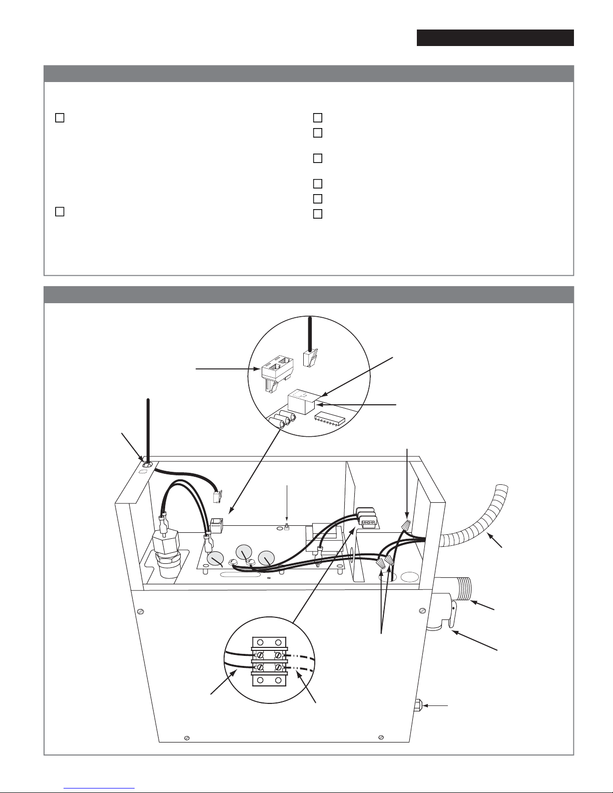
Modular Jack
Protective
Covering
(Remove)
Multi-Conductor
Control Cable
(25 feet)
Black Plastic
Strain Relief
Clamp Ground
Connection
Electrical
Supply Wire
208/240V
L1 & L2 Power
Connections
Steam Outlet
Safety Valve
Optional Steamist
Splitter for Two
Controls Plug
®
Optional Auto
Drain Connection
Terminal Strip
for Auto Drain
Connection
½" Outlet
When not equipped
with Optional Auto
Drain this line should
remain capped
Test Switch
The proper size Steam Generator has been selected by
using the sizing page in the “Full Line Brochure,” “Pricing
Guide,” or “The Generator Sizing Guide” in the Residen-
tial Systems/Steambath Product Information section of
the Steamist web site - www.steamist.com.
CAUTION: An improperly sized Steam Generator will
NOT produce the amount of steam necessary to reach
selected temperature.
The proper voltage Steam Generator has been selected
(i.e., 208V or 240V). A 208V Generator operating on
240V will damage the heating element, and a 240V
Generator operating on 208V will result in a 25%
loss of power.
The Steam Generator is installed in an upright position.
The proper sized 90°C wire and circuit breaker have
been used.
The circuit breaker is NOT a GFI (Ground Fault
Interrupter) type.
The Steam Generator is properly grounded.
The circuit breaker or disconnect switch is on.
Water supply is open to the Steam Generator.
Electrical Installation Instructions
Checklist Models: SM-5, SM-7 and SM-9
Figure 2 - Internal Electrical Connections
06/10
Before starting, insure that the conditions of the following checklist have been met:
Pub. No. 280-A
- 2 -
START
STOP
®
TEMPERATURE
START
STOP
WARNIN G
HOLD THIS FITTING SECURELY WITH A PIPE
WRENCH WHILE MAKING A PLUMBING
CONNECTION TO THE WATER INLET IN ORDER
TOPREVENT INTERNAL DAMAGE TO THE WATER
SOLENOIDVALVE. 009-1054
CUS
®
LISTED995C
STEAMBATHGENERATOR
MODELNO.
SERIALNO. HEATERLOAD
VOLTS PH MAXAMPS kW
CONTROL CIRCUIT
VOLTS AMPS 50/60HZ
SERVICEBY AUTHORIZED PERSONNEL ONLY
APRODUCT OF STEAMIST CO., RUTHERFORD, NJ
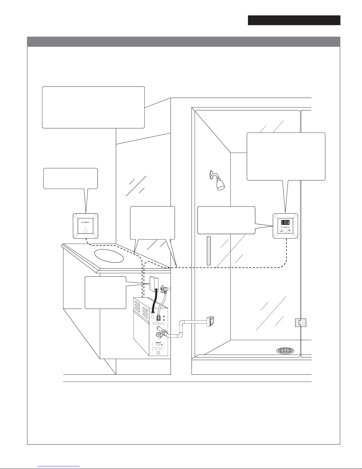
IMPORTANT: Run the Control Cable through a ¾" conduit. Remove protective cap when making the
final connection to Control.
The Electrical Instructions must be given to the homeowner for future use.
SMC-150 or TC-150
Control MUST be
installed inside the
steam room.
NOTE: Unit must be wired with 90°C wire
in a suitable raceway, or, if local codes
allow, provide twist lock plug on a 90°C
wire cord from generator to a 250V
2-pole, 3-wire grounding receptacle
(amperage rating as required).
Control Cable
Route from
Control to Steam
Generator in a
¾" conduit.
Appropriately
fuse protected
208/240V field
wiring to Steam
Generator.
Inside Installation
Control should be mounted four
feet from the floor. Select a
location convenient to the
bather but not in a direct line of
Shower or Body Sprays and not
directly above the Steamhead.
SMC-120 or TC-125
Auxilary Outside
Control
Electrical Installation Instructions
Figure 3 - Typical Installation Models: SM-5, SM-7 and SM-9
06/10 Pub. No. 280-A
- 3 -
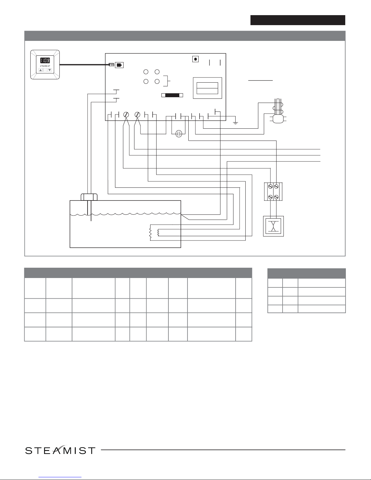
®
P14
P12
P11
P16
P15
P10
P1
P2
P6
P8
P7
P9
P3
P5
H
XL
P18 P17
DS1
DS2
DS3
DS4
See
Chart
Test
Switch
Fuse 0.15 AMP
P13
GND
TANK
WT
GY
GN
Water
Level
Probe
GN
GN
Auto Drain
Thermostat
BL
BL
Water
Solenoid
Valve
Optional
Auto Drain
Valve
Terminal
Block
BK
OR
OR
BK
BK
GN
OR
OR
BK
BK
L1
L2
GND
Field
Connections**
NOTES:
*Supplied with Controller.
**Field connections, use 90ºC wire, gauge
no.See Chart copper.
TEMPERATURE
START
STOP
Typical
Steamist
Control
(Low Voltage)
Multi-Conductor
Cable*
LLC-1300-3 Circuit Board
Heating
Elements
* NM-B type cable does not follow the 90ºC wire guideline. The NEC
requires NM-B type cable max current to be de-rated. Always follow
local and national electrical codes.
Electrical Installation Instructions
Wiring Diagram for Models SM-5 through SM-9 Models: SM-5, SM-7 and SM-9
06/10 Pub. No. 280-A
- 4 -
Specication Chart
8
8
9
5
7
300 38
44
10
10
8
6
30
30
40
45
50
60
Model
No.
Max. Cu. Ft.
For Area
Up To KW Volt Phase Amps
*Wire Size
90ºC Copper
AWG Line
Fuse
SM-9
SM-5
SM-7 210
90 240
208
240
208
240
208
1
1
1
1
1
1
21
24
29
34
Product
No.
5010
5011
7010
7011
9010
9011
DS1
DS2
DS3
DS4
GRN
YEL
AMB
RED
TIMER ON
HEAT ON
WATER FILL ON
POWER ON
LED Color Chart
East Coast Office: 25 E. Union Ave., East Rutherford, NJ 07073 • Tel: 800-577-6478 • Fax: 201-933-0746
West Coast Office: Tel: 800-355-6478 • Fax: 661-940-1617
®
This manual suits for next models
2
Other Steamist Iron manuals


Popular Iron manuals by other brands

Philips
Philips PerfectCare Pure GC7600 manual

Rowenta
Rowenta Master DW9055U1 Instructions for use

Hamilton Beach
Hamilton Beach 14875 use & care

POLTI
POLTI VAPORELLA FOREVER SUPER CLEAN Usage instructions

Clatronic
Clatronic DB 3486 instruction manual

Sunbeam
Sunbeam HOT-2-TROT TRAVEL IRON instruction manual


Dawlance
Dawlance DWSI-7282 user manual

CTC Union
CTC Union Clatronic DBS 3634 instruction manual

Clatronic
Clatronic Inox Selfclean DB 2971 Instruction manual & guarantee

HOFFEN
HOFFEN SI-9152 instruction manual

Harvia
Harvia HGX20XW Instructions for installation and use

T-Fal
T-Fal Primaglide Diffusion FV22 Series manual