Steamist HC-9 User manual

80 100
120
140
60
40
20
0psi

Table of Contents
10/08 Pub. No. 600-A
Table of Contents
I. Important Steam bath Safety Guidelines.......................................................................
II. Warning Sign Installation...............................................................................................
III. Pre-Installation...............................................................................................................
IV. Rough-In........................................................................................................................
V. Installation......................................................................................................................
VI. Digital Command Center Installation..............................................................................
VII. Digital Commercial Control Package Operation.............................................................
VIII. Warranty information......................................................................................................
List of Illustrations
Warning Sign..............................................................................................................................
Figure 1 - Dimensional Drawing for Heavy Commercial Steam Generator
(HC-9 thru HC-18).....................................................................................................................
Figure 2 - Cables......................................................................................................................
Figure 3 - Typical Steam Generator Installation........................................................................
Figure 4 - Sensor Installation (Inside Steam Room).................................................................
Figure 5 - User Control Panel...................................................................................................
Figure 6 - Main Control Panel...................................................................................................
Programming Examples............................................................................................................
Specifications Chart..................................................................................................................
Wiring Diagram.........................................................................................................................
Page
1
1
2
3
4
5
6
12
Page
1
2
3
3
5
6
7
8
10
11

10/08 Pub. No. 600-A
- 1 -
Important Steam Bath Safety Guidelines
I. Important Steam Bath Safety Guidelines:
A) Do not permit children to use the steam bath unless
they are closely supervised at all times.
B) Wet surfaces of the steam enclosures may be
slippery. The floor should be skid resistant. Bathers
should use care when entering and leaving.
C) The steam head is hot. Bathers should not touch
the steam head and avoid contact with steam near
the steam head.
D) Prolonged use of the steam bath can excessively
raise the internal human body temperature and
impair the body’s ability to regulate its internal
temperature (hyperthermia). Limit the use of steam
to 10 – 15 minutes until you are certain of your
body’s reaction.
E) Excessive temperatures have a high potential for
causing fetal damage during the early months of
pregnancy. Pregnant or possibly pregnant women
should consult a physician regarding correct expo-
sure. Obese persons and persons with a history of
heart disease, low or high blood pressure, circula-
tory system problems, or diabetes should consult a
physician before using the steam bath.
F) Persons using medication should consult a physi-
cian before using a steam bath since some medica-
tion may induce drowsiness while other medications
may affect heart rate, blood pressure and circula-
tion.
G) The Facility manager should fully understand the
causes, symptoms, and effects of hyperthermia
which may be described as follows: Hyperthermia
occurs when the internal temperature of the body
reaches a level several degrees above the normal
body temperature of 98.6° F. The symptoms of
hyperthermia include an increase in the internal
temperature of the body, dizziness, lethargy, drowsi-
ness, and fainting. The effects of hyperthermia
include:
1) Failure to perceive heat.
2) Failure to recognize the need to exit the steam
bath.
3) Physical inability to exit the steam bath.
4) Unawareness of impending risk.
5) Fetal damage in pregnant women.
6) Unconsciousness.
WARNING: The use of alcohol, drugs, or medication can
greatly increase the risk of hyperthermia.
II. Warning Sign Installation:
The warning sign shown below and provided with the
generator MUST be permanently installed on the steam
room door or the wall immediately adjacent to the steam
room.
WARNING
1. EXIT IMMEDIATELY IF UNCOMFORTABLE, DIZZY, OR SLEEPY. STAYING TOO LONG INA
HEATEDAREAIS CAPABLE OF CAUSING OVERHEATING.
2. SUPERVISE CHILDRENATALLTIMES.
3. CHECK WITH DOCTOR BEFORE USE IF PREGNANT, DIABETIC, IN POOR HEALTH, OR
UNDER MEDICALCARE.
4. BREATHING HEATEDAIR IN CONJUNCTION WITH CONSUMPTION OFALCOHOL, DRUGS,
OR MEDICATION IS CAPABLE OF CAUSING UNCONSIOUSNESS.
5. DO NOT CONTACT STEAM HEAD OR STEAMATTHE STEAM HEAD.
REDUCE THE RISK OF OVERHEATING AND SCALDING
REDUCE THE RISK OF SLIPPING AND FALL INJURY
1. USE CARE WHEN ENTERING OR EXITING THE STEAM ROOM, FLOOR MAY BE SLIPPERY.
NOTE: FORADDITIONAL SAFETYCONSIDERATIONS SEE OWNERS MANUAL.
!

17"
80 100
120
140
60
40
20
0psi
19"
7¾"
2¾" 1¼"
9"4½" 7"
5½"
2⅜"
15psi
Safety Valve
¾" NPT Outlet
Water
Column
Sight
Glass
Assembly
Steam Outlet
½" NPT
Electrical
Power box
Indicator
Light
Operating
Pressure
Cotnrol
Pressure
Gage
Water Solenoid,
Valve ¼"
Drain Valve ½" NPT
when with manual
drain, 1” when with
optional Auto Drain
Water Inlet,
Strainer
½" NPT
Auxiliary Manual Reset
Pressure Cutoff
Pre-Installation
10/08 Pub. No. 600-A
- 2 -
The Heavy Commercial steam generator (HC-9 thru
HC-18) comes from the factory assembled, carefully
wired, and tested. Please read all instructions before
installing or servicing.
IMPORTANT:
1. All Plumbing and Electrical work must conform to local
and national codes.
2. All power must be OFF to the steam generator when
installing or servicing the unit.
3. Do not use or install unauthorized components,
accessories or products on the generator or its' piping.
III. Pre-Installation:
The following general information should be used in
conjunction with your architect, designer and contractor
in providing a suitable and safe steam room environment
for the steam bathers.
A) Insure that the model steam generator unit
purchased is sized adequately for your steam room.
IMPORTANT: Refer to the specification plate affixed
to the cabinet of the steam bath generator.
B) Be sure to have the proper electrical supply. Deter-
mine proper size of wire, voltage, amperage, and
phase for the steam generator based on the specifi-
cation plate attached to the generator and the chart
in the back of this manual.
C) Provide an inline fuse/circuit breaker as required
sized in accordance with specification plate. Do not
install a GFI Ground Fault Interrupter to this equip-
ment.
D) Select a location to install the generator to allow
sufficient room (See Access Area Requirements) for
access to the unit in the event service is required.
Select a clean dry indoor location protected from
freezing. Do not store flammable materials such as
gasoline, thinners, paints, etc. in the same area as
the steam generator. Do not store corrosive materi-
als such as chlorine near the steam generator.
E) For safe low temperature draining (blow down) of
the steam generator it may be necessary to drain
into an ASME blow down tank. If required additional
space for the tank will be necessary. Consult with
your architect or licensed plumber. The blow down
process can potentially dump boiling water down
the drain and damage the drainage system.
F) The steam generator should be located as close as
possible to the steam room. If the steam generator
is more than ten feet from the steam head, insulate
the steam pipe with appropriate pipe insulation
rated for a minimum of 212ºF.
G) The serial number plate should be visible.
H) The steam room must be completely sealed on all
sides, top and bottom. Floor, walls, and ceiling
should be completely covered with waterproof
material. Floor and bench materials must be slip
resistant.
I) Provide a floor drain inside the steam room for
condensate run-off and steam room cleaning.
J) Only water tight lighting fixtures approved for the
application should be used.
Figure 1 - Dimensional Drawing for Heavy Commercial Steam Generator (HC-9 thru HC-18)

18"
Water Line, ½" NPT - Run
from a cold water pipe.
Provide a local shut-off valve.
Motorized Drain Valve
(Optional) - Use a 1" pipe routed
to an indirect waste line to be
used for the drain.
Safety Relief Valve, ¾" NPT -
Connect to indirect waste or as
required by local codes
Commercial HC Stand
(Optional)
Product Number 68005
Temperature Sensor -
Single tier seating 6 feet
above floor or Double tier
seating 7 feet from the floor
Digital Command Center -
Cable supplied is 50’ in
length. 100’ cable is
available by special order.
Maximum functional cable
length is 100 feet.
User Bypass Control -
Cable supplied is 50’ in length.
100’ cable is available by special
order. Maximum functional cable
length is 100 feet. Steam Outlet,
¾" NPT
Utility RoomSteam Room
Steam Line,
¾" Copper
User Bypass Control Cable
(6-pin Connector)
Digital Command Center Cable
(4-pin Connector)
Female End
To Generator
Female End
To Generator
Male End
To Control
Male End
To Control
Figure 2 - Plumbing Diagram
Rough-In
IV. Rough-In:
A) Plumbing Rough-In:
The heavy Commercial “HC” Steam Generator
requires the following connections: 1/2" NPT piping
for the water inlet, 3/4" copper tubing for steam
outlet, and 3/4" NPT safety valve should be piped to
an indirect waste line. A ½” drain line for a manual
drain or a 1” drain line for an optional auto blow
down assembly must be provided to route to an
indirect waste.
1) Rough-in a ½" water line from a cold water pipe.
Provide a local shut-off valve.
2) Rough-in the steam line using 3/4" copper
tubing. Do NOT use iron or galvanized pipe, it
will rust and discolor wall of steam room. For a
steam line that is longer than 10 feet use an
appropriate pipe insulation rated for a minimum
of 212ºF. The steam head should be located
approximately 18" above the floor and as far
from the bather as possible. Do NOT install
shut-off valves in this line. Do NOT create traps
or valleys in this line which would trap conden-
sation and block the flow of steam.
3) Rough-in a ½” drain line for a manual drain or a
1” drain line for an optional auto blow down
assembly and provide for an indirect waste, to
be used for draining steam generator.The
indirect drain must be in accordance with local
plumbing codes.
4) Rough-in a drain line using ¾" pipe routed to an
indirect waste from the Safety Relief valve. The
discharge end of this pipe must not be
restricted in any way. It must be piped in a way
that would safely discharge steam and/or
boiling water in the event of a failure. Always
follow local plumbing codes.
B) Electrical Rough-in:
1) Route power supply cable to the location where
the steam generator will be installed.
2) Route control cables as described in the Digital
Command Center.
10/08 Pub. No. 600-A
- 3 -
Figure 3 - Typical Steam Generator Installation
Figure 2 - Cables

Rough-In / Installation
C) Digital Commercial Control Package rough- in:
The DCCP is factory wired for either one or two
steam rooms. The following installation instructions
are typical for both room installations. IMPORTANT:
The command center cable, USER BYPASS
CONTROL cable and sensor cable are not the
same and must not be confused. Also the cables
must be routed in the proper direction.
1) Digital Command Center rough-in: Route the
command center cable in the proper direction
from the generator to the selected dry mounting
location convenient to the facility operator.
Make sure the generator end of the cable is
located near the generator mounting location
and the control end is located near the control
mounting location. Important: the cable is 50’
long. 100’ cable is available by special order.
Maximum functional cable length is 100 feet.
2) USER BYPASS CONTROL: Route the USER
BYPASS CONTROL cable in the proper
direction from the generator to the selected
location outside the steam room door. Make
sure the generator end is located near the
generator mounting location and the control
end is located near the control mounting
location. Important: the cable is 50’ long. 100’
cables are available by special order. Maxi-
mum functional cable length is 100 feet.
3) Room Temperature Sensor: Route the tempera-
ture sensor cable in the proper direction from
the generator to the selected location inside the
steam room. For sensor installation and
location, see Figure 3. Make sure the generator
end is located near the generator mounting
location and the sensor end is located near the
sensor mounting location. Important: the cable
is 50’ long. 100’ cables are available by special
order. Maximum functional cable length is 100
feet.
10/08 Pub. No. 600-A
- 4 -
V. INSTALLATION
A) Plumbing Installation: Care must be taken when
installing the steam generator. Leave proper access
for servicing (See Installation Area Requirements).
(Refer to Figure 2 for typical steam generator
installation.) CAUTION: The steam generator is
designed to be used ONLY in an upright and level
position; to do otherwise would damage the unit and
void the warranty. For convenient access mount the
steam generator on the optional Steamist stand
designed specifically for the steam generator.
1) Water supply: Purge the water supply line
before connecting to the steam generator. In
areas where high water pressure may be a
problem a water hammer arrestor should be
installed.
2) Steam line: Connect the steam line from the
previously roughed-in location to the steam
solenoid valve on the generator marked “steam
outlet.” If the generator is equipped to provide
steam to two rooms care must be taken to
make sure the proper steam solenoid is piped
to the proper room.
3) Safety Line: Connect the 3/4" NPT safety valve
into the previously installed indirect waste line.
4) Optional automatic blow down: Pipe into the
3/4" indirect waste line.
5) In the steam room, place the center of the
escutcheon onto the steam pipe and screw the
steam head into place. Care must be taken not
to scratch the steam head or escutcheon with a
wrench. Be sure the steam slot in the steam
head is facing down.
6) The steam, safety, and drain pipes become hot
during operation and should be insulated with
appropriate rated pipe insulation to protect
against accidental contact.
B) Electrical Installation: WARNING ALL POWER TO
THE STEAM GENERATOR MUST BE TURNED
OFF.
1) Locate and remove six (6) screws securing the
access cover to the gray electrical power box.
(See Figure 1.)
2) Locate appropriate knockout found on top of the
gray electrical power box. Mount a proper strain
relief into knockout hole.
3) Strip back the power cable’s outer insulation
jacket twelve inches and insert into gray
electrical power box. Strip back insulation 1/2"
from the incoming wires: single phase (two
power and one ground). 3 phase (three power
and one ground).
4) Insert ground wire into grounding lug located on
the left side wall of the gray electrical power
box. CAUTION: insure ground wire does not
come in contact with live electrical connections.
5) Locate power block found in upper part of gray
electrical power box. Insert power wires into
proper power lug terminals on top of the block
and secure.

ENOCILIS
R
A
EL
C
.Z
O.L
F
2/1
t
eN 02
5
13
.
o
N
m
e
tI
.A
.
S.U
N
I
E
DAM
NOTE: Location of the sensor is as follows:
a) Single tier seating - 6 feet above floor.
b) Double tier seating - 7 feet above floor.
No. 8 Plastic
anchors
5/8” Hole
Cable to
Steam Generator
Temperature
Sensor and Housing
(Shipped Assembled)
No. 8 Screws
1” Long
2
3
4
5
STEPS TO INSTALL SENSOR:
1) Take new sensor assembly and connect to 50’
sensor cable. Please observe polarity of the 50’ cable.
Make sure the male end of the cable is routed toward
the sensor in the steam room.
2) Peel off adhesive backing from sensor.
3) Carefully apply silicone sealant around rear edge.
4) Feed wires back into wall and press sensor firmly to
wall (be careful to align plate holes with anchor holes).
5) Install screws, and snap chrome cover back into
place.
6) Temperature sensor assembly must form a 100%
water tight seal to the wall using silicone supplied.
1
50 Foot Sensor Cable
Male end
to Sensor
Female end
to Generator
50’ sensor cable
Figure 3
10/08 Pub. No. 600-A
- 5 -
Digital Command Center Installation
VI. Digital Command Center Installation:
WARNING: All the electrical power to the steam genera-
tor MUST be turned OFF before proceeding with instal-
lation.
A) CONTROL MODULE comes factory wired for either
one or two steam rooms. The following installation
instructions are typical for both room installations.
The configuration for one or two room is set at the
factory. When the generator is configured for two
rooms (SRP-Second Room Package must be
ordered) it will have 2 room temperature sensors
(one per room), two electric steam valves, two
USER BYPASS CONTROLs, and two steam heads.
The electric steam valves will be labeled 1 and 2.
The connections for the sensors, USER BYPASS
CONTROL(s), and aroma pumps, will all be labeled
for room 1 and room 2. It is very important to pay
special attention not get the connection to room 1
and room2 crossed. This will be very difficult to
troubleshoot. If the generator is configured for one
room there will not be any special markings.
B) USER BYPASS CONTROL(s): The USER BYPASS
CONTROL should be located outside the steam
room door convenient to the bather. This control
gives the bather limited control of the steam room.
The system will operate without this control but this
function is lost. See the operating instructions for
further information on this function. Route the USER
BYPASS CONTROL wire from the selected mount-
ing area to the control module on the steam genera-
tor. The USER BYPASS CONTROL mounts to
2-1/8” or 55 mm round hole in the wall.
C) DIGITAL COMMAND CENTER is intended to be
used solely by the manager. It should be located at
a convenient height for programming. It may be
mounted on the wall of the utility room near the
steam generator, in the manager’s office, or the
front desk. The factory supplied wire is 50 feet long,
therefore DCC must be located within its reach.
IMPORTANT: The digital command center is unique
and not to be confused with the USER BYPASS
CONTROL wires or the sensor wires. The Digital
Command Center uses a 4 wire connector, the
USER BYPASS CONTROL uses a 6 wire connector
and the room sensor uses a 2 wire connector.
Route the Digital Commander Center wire from the
selected mounting location to the control module
located on the steam generator. The Digital Com-
mand Center mounts to a hole in the wall 2-1/2”w x
7-7/8”h.
D) Room Temperature Sensor(s): The room tempera-
ture sensor is required for operation. The sensor
must be located in the steam room approximately
six feet above the floor and never closer than one
foot to the ceiling or the corner of the room. Route
the cable from this location to the control module on
the steam generator. The sensor mounts to a 5/8”
hole in the wall.
Figure 4 - Sensor Installation - Inside Steamroom

User Idle/Max Display
Idle/Max Button
Digital Commercial Control Package Operation
VII. Digital Commercial Control Package Operation:
This control is designed to maximize energy savings by
allowing the facility manager set a lower operation
temperature called IDLE TEMP and also satisfy the
steam bather with the ability to by-pass this feature on
demand by pressing the USER BYPASS CONTROL
button. Unlike a typical 24 /7 timer which has only an ON
or OFF mode, the Digital Command Center has three
modes MAX, IDLE and OFF. MAX is the normal ON
mode reserved for peak hours of use when the steam
room is held at the optimum steam bath temperature.
IDLE mode is the energy saving mode. IDLE is set
below the MAX temperature and provides a significant
energy savings. As needed, the steam bather can easily
switch to the MAX setting by pressing the button on the
USER BYPASS CONTROL.
A) USER BYPASS CONTROL: The USER BYPASS
CONTROL button is only functional during the IDLE
mode. In the IDLE mode the USER BYPASS
CONTROL, typically mounted at the entrance to the
steam room, is waiting for the user to press the
button and select the MAX mode. IDLE mode is
indicated on the USER BYPASS CONTROL by one
lit bar. Pressing the USER BYPASS CONTROL
button starts the MAX CYCLE TIMER and immedi-
ately begins to heat the room to the MAX setting.
This temporary MAX CYCLE TIMER is program-
mable up to 60 minutes by the facility manager.
MAX TEMP mode is indicated by all bars lit. When
the Digital Command Center is set to MAX TEMP
the USER BYPASS CONTROL icon displays max
(all bars lit). In the MAX TEMP mode the USER
BYPASS CONTROL buttons do not function. When
the DIGITAL COMMAND CENTER is in the OFF
mode the USER BYPASS CONTROL icon will be off
(no bars lit) and the user buttons do not function.
B) Programming the DIGITAL COMMAND CENTER
can be broken down into 3 separate sections, SET
EVENT, SET VALUE, and SET CLOCK. The
buttons on the control are grouped accordingly. SET
EVENT is used to set the time and day that a
particular mode (MAX, IDLE, or OFF) is to begin.
SET VALUE is intended to set the MAX and IDLE
temperature as well as the MAX CYCLE TIMER.
The SET CLOCK section is only for adjustment of
the current time and day. The DIGITAL COMMAND
CENTER display light comes on when any button is
pressed. The light will remain on for 5 minutes after
the last button is pressed.
1) SET CLOCK: The SET CLOCK section of the
Digital Command Center is used exclusively for
setting the current time and day. It is a conve-
nient place to make changes for daylight
savings time without having to reprogram other
settings. The clock has a battery backup in the
Control Module that will keep time for up to one
year with no power.
(a) DAY Setting: Press the lower DAY button
to toggle the current day of the week.
(b) HOUR Setting: Press the lower HOUR
button to select the current AM or PM hour
and the correct hour will be displayed.
(c) MINUTE setting: Press the Lower MINUTE
button until the correct minute is displayed.
2) SET VALUE: The SET VALUE section of the
keypad is used to program the following 4
parameters:
(a) MAX1 TEMP is used to set the maximum
desired operating temperature of the
steam bath. It is set by pressing the button
until the preferred maximum temperature is
displayed. Note: The MAX TEMP cannot
be set lower than the IDLE TEMP. Selec-
tion of the MAX TEMP setting is at the
discretion of the facility manager.
(b) MAX2 TEMP (only available with SRP) is
used to set the desired operating tempera-
ture of a second steam room. It is
programmed the same as MAX1 TEMP.
(c) IDLE TEMP is used to program a lower
temperature setting during periods of less
frequent usage. It is set by pressing the
button until the desired set-back tempera-
ture is displayed. The feature can be
disabled by setting it to 00.The IDLE TEMP
cannot be set higher than the lowest MAX
TEMP value.
10/08 Pub. No. 600-A
- 6 -
Figure 5 - User Control Panel

Daily Program Number
Keypad lock
Clock
Max Temperature/Current
Temperature for Room 1
Idle Temp
24/7 Event Programming
buttons
Timer/Temperature setting
buttons
Lock Button
Time of day setting
Max/Idle/Off mode indicator
Day of the week indicator
AM/PM indicator
Max Temperature/Current
Temperature for Room 2
0-60 Minute Max Cycle Timer
Digital Commercial Control Package Operation
3) SET EVENT: Before programming the SET
EVENT, it is necessary to determine the hours
the steam bath will operate and in which mode.
Each day of the week can have up to six events
programmed. The chart on the following page
will help organize your plan for the SET EVENT
function. The top 2 sections of the chart are
filled in with 2 examples
10/08 Pub. No. 600-A
- 7-
(d) MAX CYCLE TIMER is used to set the
duration that the system will be in MAX
TEMP mode after the USER BYPASS
CONTROL button is pressed in. It is set by
pressing the corresponding button on the
Digital Command Center. Each time the
button is pressed the minutes will increase
in one minute increments from “:00” to
“:60”. If the MAX CYCLE TIMER is
programmed to “:00”, this feature will be
disabled and the USER BYPASS
CONTROL(S) will be disabled.
(e) Degree °C or °F change is made by
placing a jumper over the CN109 pins for
°C or by removing it for °F (Jumper not
included). The power must be OFF when
making this change. See Command
Module on Wiring Diagram page 11.
Figure 6 - Main Control Panel

10/08 - 8 -
Digital Commercial Control Package Operation
Pub. No. 600-A
EXAMPLE 1 shows the club opening at 7AM. Assuming
it is not busy the first hour so the mode is selected as
IDLE. Then at 8AM it gets busy and the program
switches to MAX. At 10AM it slows down again and the
control switches back to IDLE. Then at 3PM it gets busy
again and switches to back to MAX. At 7PM we switch
back to IDLE and 10PM the club closes.
EXAMPLE 2 shows the club opening a 7AM and set to
IDLE all day until 10PM when the club closes. This
would yield maximum energy savings and is the recom-
mended program.
At any time the system is in IDLE mode the user can
activate the MAX TEMP mode by pressing the USER
BYPASS CONTROL button.
Photo copy the chart and use it as a work sheet to plan
you settings:
PROG # 1 2 3456
EXAMPLE 1 MAX
IDLE
OFF XXXXXX
TIME 7:00AM 8:00AM 10:00AM 3:00PM 7:00PM 10:00PM
PROG # 1 2 3456
EXAMPLE 2 MAX
IDLE
OFF XX
TIME 7:00AM 8:00AM 10:00AM 3:00PM 7:00PM 10:00PM
TU
MAX
IDLE
MAX
IDLE
FR OFF
OFF
TIME
SU MAX
IDLE
OFF
MAX
OFF
TH
IDLE
MO
WE
SA MAX
IDLE
OFF
PROG # 1 2 3456
TIME
TIME
TIME
TIME
TIME
TIME
MAX
IDLE
OFF
MAX
IDLE
OFF

Digital Commercial Control Package Operation
10/08 Pub. No. 600-A
- 9 -
4) Programming SET EVENT: To program the
SET EVENT section, first press the PROG#
button on the Digital Command Center. The
display will flash the current program number
and show the start time of that program. The
program can only be changed while flashing. To
enter a new program, first press the DAY button
in the upper SET EVENT section to choose the
individual day or a block of days (i.e. M-TU-W-
TH-F, or SU-M-TU-W-TH-F-SA). With the
proper day(s) selected, set start time for
program 1 using the upper HOUR and MIN
buttons. Be sure to select the proper AM or PM
hour. Then press the MAX/IDLE/OFF button to
choose the mode for program 1. Program 1 is
complete. Press PROG# button to get to
program 2. Enter the start time of program 2
and select the mode. You are only program-
ming the start time of each program. The end
time is automatically the start time of the next
program. The last program entered is limited to
11:59PM. If the facility operates beyond
midnight, program 1 of the next day must be
set to 12:00 AM for continuous operation.
Follow the same process for all the programs
and days of the week. To exit the programming
mode, press the ENTER button or wait 30
seconds and it will stop blinking and your
changes will be saved. The DIGITAL COM-
MAND CENTER needs a minimum of two
programs per day to function as shown in
EXAMPLE 2. The first must be IDLE or MAX
and the last program must be OFF mode. Note:
Programs 1 through 6 are sequential and
therefore it will not be possible to set a new
program before the end of the previous
program.
(a) Programming Tip: To modify an existing
program press the PROG# button and the
upper DAY button to get to highlight the
program you want to change. Then modify
the setting with the appropriate button.
Entries will be saved automatically in 30
seconds or by pressing the enter button.
(b) Programming Tip: If the facility operates
on nearly the same schedule every day, it
may be easier to program all seven days to
the same common program and then go
back and program Sunday to be off if the
facility is closed that day.
(c) Programming Tip: You can review your
program by pressing the PROG# button
and toggling through the programs and
toggling through the days of the weeks,
and observing the time settings. If you
made no changes simply press the enter
button to return to normal or it will return in
30 seconds.
(d) Programming Tip: When reviewing the
program and a block of days are selected,
if all the individual programs for those days
do not match, the clock will display --:--.
This is normal and any adjustments made
at this time will reprogram all days selected
to match the new entry.
5) Manager lock function: The Digital Command
Center has a locking feature that prevents any
setting to be changed when locked. To lock the
control, press the lock button, the lock icon will
flash for up to 30 seconds. While the icon is
flashing, press any three consecutive buttons,
and then press the lock button again to confirm.
The three consecutive buttons pressed are the
password. The system control will be locked
and the lock icon will be on steady. To unlock,
press the lock button and then press the same
three consecutive buttons as the previous
password, the system will be unlocked and the
lock icon will disappear. If the password is lost
or forgotten, it can be reset. This will require
two people. Turn off the main power (circuit
breaker), have a second person then press and
hold the lock button on the Digital Command
Center while the first person turns the power
back on. The system will be unlocked. Also see
the reset section for an alternate method (step
11).
6) Temporary Mode setting: By pressing
IDLE/MAX/OFF button on the Digital Command
Center you can temporarily change the current
mode (IDLE/MAX/OFF). This is only a tempo-
rary change until the next programmed event.
7) Auto-Blow Down: The optional auto-blow down
becomes active in the OFF mode. When first
entering OFF mode, the steam valves will
deactivate and the generator will continue to
maintain normal pressure. After 5 minutes the
generator will shut down and the drain will
open. Boiling water will exit under pressure and
the water valve will turn on to help flush the
generator. After 2 minutes the drain will close
and the generator will refill. After a total of 7
minutes the generator is ready to start a new
cycle. If the facility is operated 24 hours a day,
a 7 minute OFF mode should be programmed
in to allow for a proper drain cycle. In areas
where the water is hard, a second drain cycle
can be programmed by adding an extra 7

10/08 Pub. No. 600-A
- 10 -
Digital Commercial Control Package Operation
minute OFF mode during an “Off-Peak” daytime
period. IMPORTANT: Due to possible code
violations or damage to the building drainage
system the hot boiling water exiting in this
process may require a Blow-Down Tank.
Consult with your licensed contractor. Blow-
Down tanks may be purchased separately.
8) Steam Control: The steam valve(s) are
controlled according to the room temperature
sensor(s) and the programmed mode. When
the room temperature is lower than the set
temperature by one degree the steam valve will
turn on. When it reaches the set temperature it
turns off. If for some reason the room tempera-
ture exceeds the MAX TEMP setting (of either
room) by more than 10 degrees the Digital
Command Center will turn off the generator
until that room temperature drops to 1 degree
below the set temperature.
9) Aroma Control: There are two aroma control
relays (one for each room) located in the
Command Module on the generator. These
relays can be used with most aroma pumps
available. The relays are programmed to
conserve aroma therapy oil. The relays are only
on when the following conditions are met. The
program for that room must be in the MAX
mode, the steam valve for that room must be
on and the temperature in that room must be
above the IDLE setting. When all these condi-
tions are met, then the aroma relays will
energize.
10) Fahrenheit and Celsius: The Fahrenheit or
Celsius temperature can be selected by
changing a jumper in the Command Module
(CN109). When it is not connected (open
circuit), it will be Fahrenheit. When it is
connected, it will be Celsius. The Jumper must
be switched with power off (See wiring diagram
on page 11).
11) Reset Feature: If it is ever necessary to reset
all the programs and start over press and hold
the PROG# button and the lower MIN button for
five seconds simultaneously. This will reset
every setting in the Command Center. This
process can also be used to unlock the control
if the password is lost or forgotten.
Model
No. Product
No. KW
Volts/
Phase/
Amps
Wire Size
90ºC
Copper AWG
Shipping
Weight
HC-9
HC-12
HC-15
HC-18
Specifications Chart
60900
60901
60902
60903
60904
61200
61201
61202
61203
61204
61500
61501
61502
61503
61504
61800
61801
61802
61803
61804
9
12
15
18
Max.
Cu. Ft.
400
500
620
740
240/1/38
208/1/43
240/3/22
208/3/25
480/3/11
240/1/50
208/1/58
240/3/29
208/3/33
480/3/15
240/1/63
208/1/72
240/3/36
208/3/42
480/3/18
240/1/75
208/1/87
240/3/43
208/3/50
480/3/22
8
6
10
8
14
6
4
8
8
12
4
4
8
6
10
3
3
6
6
10
Water
Inlet Steam
Outlet
Dimensions
22-1/2”x19”x28”
22-1/2”x19”x28”
22-1/2”x19”x28”
22-1/2”x19”x28”
140 lbs.
150 lbs.
150 lbs.
150 lbs.
1/2” NPT
1/2” NPT
1/2” NPT
1/2” NPT
3/4” NPT
3/4” NPT
3/4” NPT
3/4” NPT
Line
Fuse
50
60
30
35
15
70
80
40
45
20
80
90
45
60
25
100
110
60
70
30
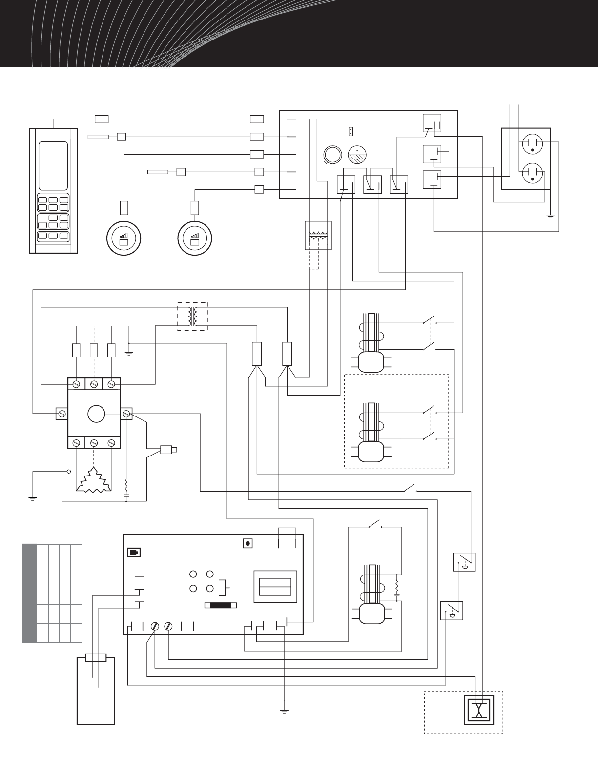
LLC-1300-6 Circuit Board
P14
P12
P11
P10
P1
P2
P6
P8
P7
P9
P4
P3
P5
L
H
XL
P18 P17
DS1
DS2
DS3
DS4
See
Chart
Test
Switch
Fuse 0.15 AMP
L1
L3
L2
T2
T1
T3
COIL
50’ Cable
50’ Cable
Digital
Command
Center
User
Bypass
Control 2
User
Bypass
Control 1
Room
Sensor 1
Room
Sensor 2
Transformer
For 480V Units
Steam Solenoid
Valve 1
Optional
Steam Solenoid
Valve 2
12V Class 2
Transformer
Steam
Switch 1
Steam
Switch 2
Incoming
Power
Fuses
Contactor
Red Heat
Light Heater Switch
Water Switch
Water
Solenoid
Pressure
Control
Optional
Auto
Blowdown
Water
Sensor
Tube
Command Module
Control
Fuses
YL
GN
GN
BN
BK
BK
RD
RD
BK
RD
OR
VT
YL
RD
GY
VT
BN
BN BK
BL
BL
RD
BK
BL
BN
BK
RD
WT
GY
Steam1
Steam2
Heater
Aroma1 Aroma2
Drain
120V, 15AMP
Branch Circuit
HN
1
2
BK14
WT14
RD14
RD14
Pressure
Limit
Control
F2 F1
50’ Cable
50’ Cable
50’ Cable
CN102
CN105
CN103
CN106
CN104
*CN109
Back up
Battery
*Note: CN109 Jumper open = F° Jumper closed = C°
Turn OFF power if making this change
RDRD
BK
BK
BN
Note: All factory wires are 18AWG unless otherwise noted.
Power and heater wire gauge are set by the factory.
BK14
CN101 12VAC
YL
YL
RD
BK
BL
**
** Note: Select
BL for 240V
RD for 208V
GN12
Note: Ground
must be on a
heater flange bolt
GN
BK14
Snubber
Snubber
10/08 Pub. No. 600-A
- 11 -
Wiring Diagram
DS1
DS2
DS3
DS4
GRN
YEL
AMB
RED
TIMER ON
HEAT ON
WATER FILL ON
POWER ON
LED Color Chart

Other manuals for HC-9
2
This manual suits for next models
23
Table of contents
Other Steamist Iron manuals


