Stec Fifty Five X Owner's manual

S-TEC
Pilot’s Operatin
g
Handboo
k
Cirrus SR20/22Aircraft
SR20: SN 1337 andAbove
SR22: SN 0435 andAbove

2nd Ed. Nov 15, 07 i
S–TEC
List of Effective Pages * Asterisk indicates pages changed, added, or deleted by
current revision.
PageNo. Issue
* 3-9 2nd Ed, 1st Rev
* 3-18 2nd Ed, 1st Rev
* 4-3 2nd Ed, 1st Rev
Record of Revisions Retain this record in front of handbook. Upon receipt of a
revision, insert changes and complete table below.
Revision Number Revision Date Insertion Date/Initials
1st Ed. Jul 15,06
1st Rev. Jul 19,06
2nd Rev. Aug30,06
2nd Ed. Nov15,07
1st Rev. Mar01,08
1st Rev. Mar 01, 08

ii 2nd Ed. Nov 15, 07
S–TEC
Page Intentionally Blank

2nd Ed. Nov 15, 07 iii
S–TEC
Table of Contents
Sec. Pg.
1 Overview...........................................................................................................1–1
1.1 DocumentOrganization....................................................................1–3
1.2 Purpose..............................................................................................1–3
1.3 GeneralControlTheory....................................................................1–3
1.4 ModesofOperation...........................................................................1–4
1.4.1 RollAxis Control.................................................................1–4
1.4.2 PitchAxis Control...............................................................1–4
1.5 BlockDiagram....................................................................................1–4
2 Pre-FlightProcedures...................................................................................2–1
2.1 Power-UpTest....................................................................................2–3
2.2 Pre-FlightTest....................................................................................2–7
3 In-FlightProcedures......................................................................................3–1
3.1 NormalOperatingProcedures........................................................3–3
3.1.1 Heading(HDG)Mode........................................................3–3
3.1.2 Navigation(NAV)Mode......................................................3–4
3.1.2.1 PilotSelectableInterceptAngle........................3–7
3.1.3 Global Positioning System Steering (GPSS) Mode.......3–8
3.1.3.1 PilotSelectableInterceptAngle.......................3–10
3.1.4 AltitudeHold(ALT) Mode..................................................3–11
3.1.5 Vertical Speed(VS)Mode.................................................3–12
3.1.5.1 NormalOperation..............................................3–12
3.1.5.2 PFDFailureOperation....................................3–12

iv 2nd Ed. Nov 15, 07
S–TEC
3.1.6 AltitudePre-SelectFunction.............................................3–14
3.1.7 Autotrim(SR22Only).......................................................3–16
3.1.8 ManualElectricTrim(SR22Only)..................................3–16
3.2 PrecisionApproach Procedures.....................................................3–18
3.2.1 Straight-InILSApproach....................................................3–18
3.2.2 ILSApproachwithProcedureTurn................................3–22
3.3 Non-PrecisionApproach Procedures............................................3–22
3.3.1 Straight-In Back CourseApproach..................................3–22
3.3.2 Back CourseApproach with Procedure Turn...............3–24
3.3.3 Straight-InLOCApproach................................................3–26
3.3.4 Straight-InVORApproach.................................................3–27
3.3.5 LOCApproachwithProcedureTurn..............................3–28
3.3.6 VORApproachwithProcedureTurn..............................3–30
3.3.7 GPSSApproach (Lateral Guidance Only).....................3–32
3.4 FlightDirector(FD)Operation.........................................................3–32
3.4.1 APMode...............................................................................3–32
3.4.2 FDMode...............................................................................3–33
3.5 WAASProcedures..............................................................................3–34
3.5.1 GPSApproach(WithVertical Guidance).......................3–34
3.5.2 MissedApproach................................................................3–34
3.6 AutopilotDisconnect........................................................................3–34
4 OperatingParameters..................................................................................4–1
4.1 RollAxis Limits..................................................................................4–3
4.2 PitchAxis Limits.................................................................................4–3
5 Glossary...........................................................................................................5–1

2nd Ed. Nov 15, 07 v
S–TEC
List of Figures
Fig. Pg.
1–1 System Fifty FiveXBlockDiagram..............................................................1–5
2–1 APDisplay,Power-UpAnnunciations........................................................2–4
2–2 APDisplay,SoftwareRevisionNumber.....................................................2–4
2–3 PFD Display, INITIALAHRSALIGNMENT Message.................................2–4
2–4 APDisplay, RDYAnnunciation....................................................................2–5
2–5 PFD Display,APRDYAnnunciation............................................................2–5
2–6 APDisplay,FAILAnnunciation.....................................................................2–6
2–7 PFD Display,APFAILAnnunciation.............................................................2–6
2–8 APDisplay, HDG Mode Engaged (Pre-Flight) ..........................................2–8
2–9 PFDDisplay, HDG Mode Engaged (Pre-Flight)........................................2–8
2–10 APDisplay, HDG andALT HOLD Modes Engaged (Pre-Flight)..............2–9
2–11 PFD Display, HDG and ALT HOLD Modes Engaged (Pre-Flight)..........2–9
2–12 APDisplay, HDGand VS Modes Engaged (Pre-Flight)..........................2–11
2–13 PFD Display, HDG and VS Modes Engaged (Pre-Flight).......................2–11
3–1 APDisplay,HDGModeEngaged................................................................3–3
3–2 PFD Display, HDGModeEngaged.............................................................3–3
3–3 APDisplay,NAVModeEngaged..................................................................3–4
3–4 PFD Display, NAV Mode Engaged,A/C on 45°InterceptAngle...............3–4
3–5 PFD Display, NAV Mode Engaged,A/C Turning onto Course.................3–5
3–6 PFDDisplay,NAV Mode Engaged,A/CTrackingCourse.........................3–6
3–7 APDisplay,APRModeEngaged.................................................................3–7
3–8 APDisplay, HDG Mode Engaged, NAV ModeArmed................................3–7

vi 2nd Ed. Nov 15, 07
S–TEC
3–9 PFD Display, HDG Mode Engaged, NAV ModeArmed..............................3–8
3–10 APDisplay, GPSS ModeEngaged..............................................................3–8
3–11 PFDDisplay, GPSS Mode Engaged...........................................................3–9
3–12 APDisplay, HDG Mode Engaged, GPSS ModeArmed...........................3–10
3–13 PFDDisplay, HDG Mode Engaged, GPSS ModeArmed........................3–10
3–14 APDisplay,HDGandALT HOLD Modes Engaged.................................3–11
3–15 PFDDisplay, HDG andALTHOLDModesEngaged...............................3–11
3–16 APDisplay, HDG and VS Modes Engaged..............................................3–13
3–17 PFDDisplay, HDG andVSModesEngaged...........................................3–12
3–18 APDisplay, HDGand VS Modes Engaged, PFD Failure........................3–13
3–19 APDisplay, HDG and VS Modes Engaged,ALT HOLD ModeArmed....3–15
3–20 PFD Display, HDG and VS Modes Engaged,ALT HOLD ModeArmed....3–15
3–21 APDisplay, HDGandALTHOLDModesEngaged.................................3–15
3–22 APDisplay,HDGandALTHOLD ModesEngaged,Autotrimin Progress.........3–16
3–23 APDisplay, NAV,APR, andALT HOLD Modes Engaged.......................3–19
3–24 PFDDisplay, NAV,APR, andALTHOLD Modes Engaged .....................3–19
3–25 APDisplay,NAV,APRandALTHOLDModesEngaged,GSModeArmed .......3–20
3–26 PFDDisplay, NAV,APRandALTHOLDModesEngaged, GSModeArmed......3–20
3–27 APDisplay, NAV,APR and GS Modes Engaged......................................3–21
3–28 PFDDisplay,NAV,APR and GS Modes Engaged...................................3–21
3–29 Straight-InILSApproach...............................................................................3–21
3–30 APDisplay,APR Mode Engaged, Back Course......................................3–22
3–31 APDisplay,APR Mode Engaged, Back Course......................................3–23
3–32 Straight-InBackCourseApproach.............................................................3–23

2nd Ed. Nov 15, 07 vii
S–TEC
3–33 APDisplay,APRModeEngaged,TrackLOCBackCourse Outbound.............3–24
3–34 APDisplay,APRModeEngaged,Track LOCBackCourseInbound................3–24
3–35 BackCourseApproachwith ProcedureTurn..........................................3–25
3–36 APDisplay,APRModeEngaged,TrackLOC FrontCourseInbound..................3–26
3–37 Straight-InLOCApproach............................................................................3–26
3–38 APDisplay,APRMode Engaged,TrackVORFrontCourseInbound.................3–27
3–39 Straight-InVORApproach............................................................................3–27
3–40 APDisplay,APRModeEngaged,TrackLOC FrontCourse Outbound.............3–28
3–41 APDisplay,APR ModeEngaged,TrackLOC FrontCourseInbound...............3–28
3–42 LOCApproach with ProcedureTurn........................................................3–29
3–43 APDisplay,REVModeEngaged,TrackVOR FrontCourse Outbound.............3–30
3–44 APDisplay,APRModeEngaged,Track VORFrontCourseInbound...............3–30
3–45 VORApproachwithProcedureTurn........................................................3–31
3–46 PFDDisplay, HDG andALTHOLDAP Modes Engaged.........................3–32
3–47 PFDDisplay,FDModeOnlyEngaged.....................................................3–33

viii 2nd Ed. Nov 15, 07
S–TEC
List of Tables
Table Pg.
2–1 Power-Up Test...............................................................................................2–3
2–2 Pre-FlightTest...............................................................................................2–7

2nd Ed. Nov 15, 07 1-1
S–TEC
SECTION 1
OVERVIEW

1-2 2nd Ed. Nov 15, 07
S–TEC
Page Intentionally Blank

2nd Ed. Nov 15, 07 1-3
S–TEC
1.1 Document Organization
Section 1 Overview
Section 2 Pre-Flight Procedures
Section 3 In-Flight Procedures
Section 4 Operating Parameters
Section 5 Glossary
1.2 Purpose
This Pilot's Operating Handbook (POH) provides Pre-Flight and In-Flight
operating procedures for the S-TEC System Fifty Five X Autopilot (AP), installed
in the Cirrus SR20/22 aircraft (A/C), and integrated with the Avidyne Primary
Flight Display (PFD), as well as the Garmin 400/500 Series or 400W/500W
Series Navigation Receiver.
Note:
This POH must be carried in the A/C and made available to the pilot at
all times. It can only be used in conjunction with the Federal Aviation
Administration (FAA) approved Aircraft Flight Manual (AFM) orAircraft Flight
Manual Supplement (AFMS). Refer to the applicable AFM or AFMS for
A/C specific information, such as unique ground tests, limitations, and
emergency procedures.
Note:
The System Fifty Five X autopilot is a tool provided to Cirrus SR20/22 aircraft
owners, that serves to assist them with cockpit workload management. The
ability of the autopilot to provide optimum assistance and performance is
directly proportional to the pilot's knowledge of its operating procedures.
Therefore, it is highly recommended that the pilot develop a thorough
understanding of the autopilot, its modes, and operating procedures in
Visual Meteorological Conditions (VMC), prior to using it under Instrument
Flight Rules (IFR).
1.3 General Control Theory
The System Fifty Five X is a rate based autopilot. When in control of the roll axis,
the autopilot senses turn rate, as well as closure rate to the selected course,
along with the non-rate quantities of heading error, course error, and course
deviation indication. When in control of the pitch axis, the autopilot senses
vertical speed, acceleration, and closure rate to the selected glideslope, along
with the non-rate quantities of altitude and glideslope deviation indication. These
sensed data provide feedback to the autopilot, which processes them in order to
control the aircraft through the use of mechanisms coupled to the control
system. The roll trim cartridge is coupled to the ailerons. The pitch trim
cartridge and pitch servo (selected aircraft only) are coupled to the elevator.
Activation of roll axis control must always precede activation of pitch axis control.

1-4 2nd Ed. Nov 15, 07
S–TEC
1.4 Modes of Operation
1.4.1 Roll Axis Control
Heading (HDG) Mode
Used to Turn onto a Selected Heading and Hold it
Navigation (NAV) Mode
Used to Intercept and Track a VOR/GPS Course
Approach (APR) Mode
Used to Intercept and Track a LOC/GPS Front Course Inbound
Reverse (REV) Mode
Used to Intercept and Track a LOC Back Course Inbound
Global Positioning System Steering (GPSS) Mode
Used to Laterally Steer along a Course defined by GPS
1.4.2 Pitch Axis Control
Altitude Hold (ALT) Mode
Used to Hold Altitude
Vertical Speed (VS) Mode
Used to Hold Vertical Speed
Glideslope (GS) Mode
Used to Intercept and Track Glideslope
Note:
Glidepath can herein this document be used interchangeably with Glideslope.
1.5 Block Diagram
The System Fifty Five X Block Diagram is shown in Fig. 1-1.

2nd Ed. Nov 15, 07 1-5
S–TEC
Fig. 1-1. System Fifty Five X Block Diagram

1-6 2nd Ed. Nov 15, 07
S–TEC
Page Intentionally Blank

2nd Ed. Nov 15, 07 2-1
S–TEC
SECTION 2
PRE-FLIGHT PROCEDURES

2-2 2nd Ed. Nov 15, 07
S–TEC
Page Intentionally Blank

2nd Ed. Nov 15, 07 2-3
S–TEC
2.1 Power-Up Test
Perform the actions shown in Table 2-1. For each action, verify the corresponding
response where applicable.
Table 2-1. Power-Up Test
ACTION RESPONSE
1. Set Battery Master Switch to ON
position. All annunciations appear on AP
display as shown in Fig. 2-1, and then
extinguish.
Software revision number briefly
appears on AP display as shown in
Fig. 2-2, and then extinguishes.
INITIAL AHRS ALIGNMENT
message appears on PFD display, as
shown in Fig. 2-3.
RDY annunciation alone re-appears
on AP display within 3 minutes, as
shown in Fig. 2-4 (Notes 1, 2).
Once AHRS has completed its
alignment, AP RDY annunciation
appears on PFD display as shown in
Fig. 2-5.
Notes:
1. Should a failure be detected, the FAIL annunciation alone will re-appear on
the AP display as shown in Fig. 2-6, and the autopilot will not operate. In
addition, the AP FAIL annunciation will appear on the PFD, as shown in
Fig. 2-7.
2. Should the rate gyro internal to the Turn Coordinator fail to reach sufficient
speed, the AP display will remain blank indefinitely and the autopilot will
not operate. This typically indicates that the Turn Coordinator needs repair.

2-4 2nd Ed. Nov 15, 07
S–TEC
Fig. 2-1. AP Display, Power-UpAnnunciations
Fig. 2-2. AP Display, Software Revision Number
Fig. 2-3. PFD Display, INITIALAHRSALIGNMENT Message
2nd Ed. Nov 15, 07 2-5
S–TEC
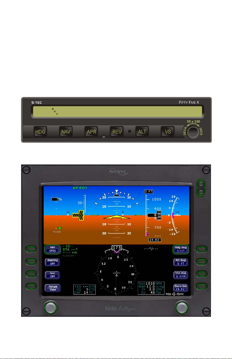
Fig. 2-4. AP Display, RDY Annunciation
Fig. 2-5. PFD Display,AP RDYAnnunciation
Other manuals for Fifty Five X
1
Table of contents
Other Stec Autopilot System manuals


