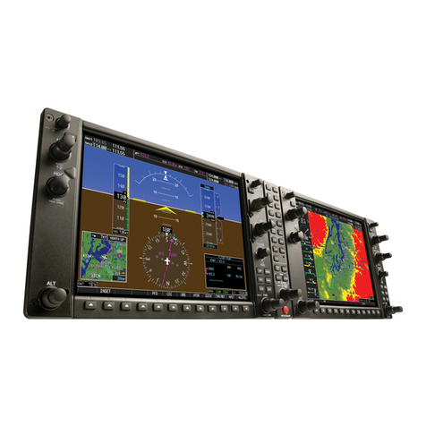
Stec System 55X User manual

System Fifty Five X
Autopilot
Pilot’s Operating
Handbook

2nd Ed: May 31, 2002 i
SYSFIFTYFIVEXPOH
List of Effective Pages * Asterisk indicates pages changed, added, or deleted by
revision.
Record of Revisions Retain this record in front of handbook. Upon receipt of a
revision, insert changes and complete table below.
Edition Number Publication Date Insertion Date/Initials
1st Edition November 8, 2000
2nd Edition May 31, 2002

2nd Ed: May 31, 2002 iii
SYSFIFTYFIVEXPOH
TABLE OF CONTENTS
Section Page
Editons.....................................................................................................................i
TableofContents..................................................................................................iii
ListofFigures.......................................................................................................v
1.0 Introduction.........................................................................................................1-3
2.0 System FiftyFiveXBlockDiagram................................................................2-3
3.0 Autopilot Overview............................................................................................3-3
4.0 Procedures.........................................................................................................4-3
4.1 Pre-flight Procedures..........................................................................4-3
4.1.1 AutopilotSelfTest...................................................................4-3
4.1.2 Pre-flightTest...........................................................................4-4
4.1.3 ManualElectricTrimTest......................................................4-6
4.2 NormalOperatingProcedures..........................................................4-7
4.2.1 HeadingMode.........................................................................4-7
4.2.2 NAVInterceptandTracking...................................................4-7
4.2.2.1 PilotSelectable InterceptAngles (DG or HSI)...................4-9
4.2.3 Approach(APR) ModeSwitch..............................................4-10
4.2.4 GPSSteering(GPSS) Mode................................................4-10
4.2.5 GPSSOperatingProcedures..............................................4-11
4.2.5.1 PilotSelectable InterceptAngles(GPSS) Mode..............4-11
4.2.6 StandardGPS Approach......................................................4-12
4.2.7 GPSSteering(GPSS) Approach........................................4-13
4.2.8 Reverse(REV) Mode.............................................................4-13
4.2.9 Vertical Speed (VS)...............................................................4-13
4.2.10 Altitude(ALT)............................................................................4-14
4.2.11 Control Wheel Steering(CWS)..........................................4-15
4.2.12 PitchTrim Indicator...............................................................4-16
4.2.13 Autotrim..................................................................................4-16

iv 2nd Ed: May 31, 2002
SYSFIFTYFIVEXPOH
TABLE OF CONTENTS (Cont'd)
Section Page
4.3 Approach Procedures.........................................................................4-19
4.3.1 Procedure Turn Localizer Approach(Standard DG)......4-19
4.3.2 Straight-In Localizer Intercept & Tracking
(StandardDG)........................................................................4-21
4.3.3 Pilot Selectable Intercept Angles (Standard DG)...........4-22
4.3.4 Procedure Turn Localizer Approach (Optional HSI)......4-22
4.3.5 LocalizerIntercept& Tracking(Optional HSI).................4-25
4.3.6 PilotSelectable Intercept Angles(Optional HSI).............4-27
4.3.7 Glide-slopeIntercept& Tracking.......................................4-27
4.3.8 ManualArm/AutomaticCapture........................................4-30
4.3.9 Procedure Turn Localizer Back-Course Approach
(OptionalHSI)........................................................................4-31
4.3.10 Localizer Back Course Intercept and Tracking
(OptionalHSI).......................................................................4-34
4.4 SystemFailureandCautionAnnunciations..................................4-37
4.5 Autopilot Disconnect...........................................................................4-38
4.6 YawDamper (If Installed)...................................................................4-38
4.6.1 YawDamperControls.........................................................4-38
4.6.2 YawDamper PreflightProcedures...................................4-39
4.6.3 YawDamperInflightProcedures.......................................4-39
4.7 Single-CueFlightDirectorOperation(Optional)..........................4-40
5.0 SystemFiftyFiveXSpecifications................................................................5-3
6.0 Glossary..............................................................................................................6-3

2nd Ed: May 31, 2002 v
SYSFIFTYFIVEXPOH
LIST OF FIGURES
FIGURE Page
4.3.3.1 Procedure Turn Localizer Approach & Track
(StandardDG)......................................................................................4-20
4.3.4.1 ProcedureTurnLocalizer Approach&Tracking (Opt HSI)............4-24
4.3.5.1 Straight-InLocalizer Approach& Tracking (Opt HSI)....................4-26
4.3.7.1 Glide-slopeIntercept&Track.............................................................4-28
4.3.7.2 ProcedureTurnfor Glide-slopeApproach......................................4-29
4.3.9.1 Back-CourseProcedureTurn(HSI).................................................4-33
4.3.9.2 Back-Course Straight-In Approach (OptHSI).................................4-36

2nd Ed: May 31, 2002 1-1
SYSFIFTYFIVEXPOH
SECTION 1
INTRODUCTION

2nd Ed: May 31, 2002 1-3
SYSFIFTYFIVEXPOH
1.0 Introduction
The primary purpose of the System Fifty Five X Pilot Operating Handbook
(POH) is to provide pilots with step-by-step functional Preflight and In-
Flight Operating Procedures for the installed system.
This System Fifty Five X Pilot's Operating Handbook, part number 87109,
dated 31 May 2002 or later, must be carried in the aircraft and be made
available to the pilot while in flight.
NOTICE
The information in this manual must be used in conjuction
withthe FAA approved Airplane Flight Manual Supplement
(AFMS), Pilot Operating Handbook Supplement (POHS), or
Supplemental Flight Manual (SFM). Refertothe specificAFMS,
POHS, or SFM for your aircraft's specific information and
emergency operating procedures.
If the autopilot is to be used during Instrument Flight Rules
(IFR) operations, we recommend that you develop a thorough
understanding of the autopilot system, its functions and
characteristics in Visual Meteorological Conditions (VMC).
Accomplish this before undertaking an IFR flight.

1st Ed: May 31, 2002 2-1
SYSFIFTY FIVE X POH
SECTION 2
BLOCK DIAGRAM

1st Ed: May 31, 2002 2-3
SYSFIFTY FIVE X POH
2.0 Block Diagram
Fig. 2-1. System Fifty Five X Block Diagram
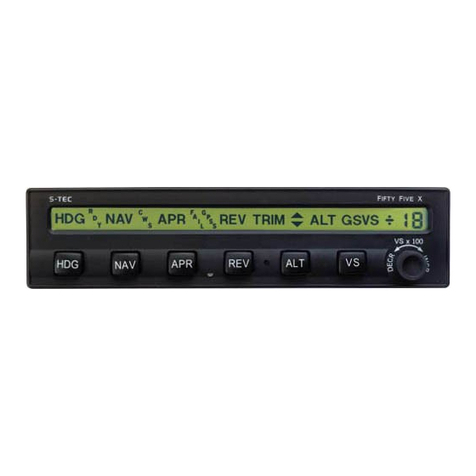
SYSTEM FIFTY FIVE X
PROGRAMMER / COMPUTER
ABSOLUTE PRESSURE
TRANSDUCER
REMOTE ANNUNCIATOR
(OPTIONAL)
ALTITUDE SELECTOR/ALERTER
(OPTIONAL)
ROLL SERVO
TRIM SERVO
(OPTIONAL)
PITCH SERVO
DSBL
D
E
C
R
I
N
C
R
HDG NAV APR REV TRIM ALT GS VS
RDY
CWS
FAIL
GPSS
VS x 100
F FX
IFTY IVE
TRIM
ON FAIL
TRIM
TRIMTRIM
TRIM
A/P DISC
TRIM INTRPT
CWS
YAW DAMPER
(OPTIONAL) YAW SERVO
(OPTIONAL)
A/P MASTER
SWITCH
TURN COORDINATOR
AUTOPILOT DISCONNECT/
TRIM INTERRUPT SWITCH
CONTROL WHEEL
STEERING SWITCH
* TRIM
MONITOR
SWITCH
TRIM COMMAND
SWITCH
* NOT AVAILABLE ON ALL AIRCRAFT
FLIGHT DIRECTOR
(OPTIONAL)
HSI
(OPTIONAL)
SYSTEM FIFTY FIVE X BLOCK DIAGRAM
SA-200 ALTITUDE PRE-SELECT
(OPTIONAL)

2nd Ed: May 31, 2002 3-1
SYSFIFTYFIVEXPOH
SECTION 3
AUTOPILOT OVERVIEW

2nd Ed: May 31, 2002 3-3
SYSFIFTYFIVEXPOH
3.0 Autopilot Overview
3.1 System Fifty FiveX Autopilot Overview
The System Fifty Five X is a rate autopilot that controls the roll and pitch axes
of the aircraft. The autopilot's main function is to convert pilot commands to
logic signals for the roll and pitch computers. As the pilot enters the desired
mode by pressing the appropriate mode selector switch, the computer
acknowledges the mode, causing the appropriate annunciator to illuminate.
The Roll Computer receives select input signals from the Directional Gyro
(DG) or Horizontal Situation Indicator (HSI), Very High Frequency Omni-
directionalRadio (VOR),Localizer (LOC) or Global Positioning System (GPS),
Deviation Indicators, and the Turn Coordinator. It then computes roll servo
commands for stabilization, turns, navigation intercepts, and tracking.
Sensing for trim annunciation or automatic elevator trim is provided by the
pitch servo. Drive for the elevator trim servo is provided by the pitch computer.

2nd Ed: May 31, 2002 4-1
SYSFIFTYFIVEXPOH
SECTION 4
PROCEDURES

2nd Ed: May 31, 2002 4-3
SYSFIFTYFIVEXPOH
4.0 Procedures
4.1 Pre-Flight Procedures
4.1.1 AutopilotSelf-Test
NOTE:
The System Fifty Five X incorporates a SELF-TEST
that requires a 100% pass rate before the autopilot
can be engaged. To perform the test, aircraft DC
electrical power must be supplied to the autopilot.
1. Autopilot Master switch..........................................................Set toFD / AP
—Observe that all segments of the Programmer / Computer display
and annunciators illuminate for 5 seconds during test.
—Satisfactorycompletion ofthe SELF-TESTis indicatedwhen the Ready
(RDY) annunciator remains on at the end of the 5-second self-test.
—Should a fault be detected, the FAIL annunciator will remain on at the
conclusion of the self-test and the autopilot will not operate.
NOTE:
If the autopilot detects the Turn Coordinator rotor speed as
low or not turning, the display will remain blank and the
autopilot will remain inoperable. In cold weather, the Turn
Coordinator may take longer to attain proper operating speed
due to temperature sensitivity. If either condition occurs,
consult your dealer before use of the autopilot is attempted.

4-4 2nd Ed: May 31, 2002
SYSFIFTYFIVEXPOH
4.1.2 Pre-flight Test
1. TrimMaster (ON /OFF)Switch....................................................................ON
2. HDGand VSswitches......................................................PRESS/RELEASE
—Ensure that HDG and VS illuminates on the Fifty Five X annunciator.
3. ControlWheelSteering(CWS) switch...........................PRESS/ RELEASE
—Verify that CWS and VS are highlighted on the annunciator.
4. CWSswitch...............................................................................PRESS/HOLD
—Verify that the autopilot servos have dis-engaged and the controls
are free.
5. CWSswitch..................................................................................RELEASE
—Servos should re-engage.
6. VSKnob........................................................................................ROTATE CW
—Pitch control should move slowly out (pilot may have to assist a
heavyyoke).
7. VS Knob......................................................................................ROTATE CCW
—Pitch control should move slowly in.
8. A/PDISC TrimInterruptSwitch(oncontrolyoke)..............................PRESS
—Verify the autopilot disconnects.
9. HDGMode...........................................................................................ENGAGE
10. DGorHSIHDGbug.................................................................MOVELT / RT
—Roll control should follow the HDG bug.
11. AltitudeHold(ALT)button......................................................................PUSH
—Slowly pull out (nose up) on the pitch control. Autotrim should run
nose down with TRIM flashing on the remote annunciator and the
autopilot computer / programmer after approximately 3 seconds.
—Slowly move pitch control foward (nose down). After 3 seconds,
autotrim should move nose up with TRIM flashing on the remote
annunciator and the autopilot computer / programmer after
approximately 3 seconds.

2nd Ed: May 31, 2002 4-5
SYSFIFTYFIVEXPOH
12. TrimMaster (ON/ OFF)Switch.................................................................OFF
NOTE:
If HSI equipped,center thecourse arrow underthe lubber
line and push the NAV button. Move the course arrow on
the HSI left then right. Roll control should follow the
course arrow. Channel a valid VOR signal and move
course arrow just enough to deflect the left / right needle
1 or 2 dots. Roll control should follow the Course
Deviation Indicator (CDI) left / right needle during the
test. (
This test is only valid if the left / right needle is
centered with the course arrow under the lubber line).
NOTE:
If DG equipped, center the HDG bug under the lubber
line. Channel a valid VOR signal. Move the OBS to cause
left / right CDI needle deflection. The roll control should
follow the left / right needle movement.
13. REVModebutton.....................................................................................PUSH
—Roll control should respond opposite to the course arrow and
CDI left / right needle inputs.
14. Autopilot Master Switch(If FD Equipped)...............................SELECT FD
—Note the roll, pitch and trim servos are disengaged. The steering
bar should be in view on the attitude indicator.
15. HDGMode...........................................................................................ENGAGE
—MOVE HDG bug 45 degrees left. The roll steering bar should slowly
indicate a left steering command. Repeat the same test for the
right side.
16. VSMode.............................................................................................ENGAGE
—SELECT 1500 FPM rate of climb. Note the pitch steering bar moves
slowly up. Repeat the same test for the down direction.
17. AutopilotMasterSwitch......................................................SELECTFD/ AP
—The servos should re-engage.
18. TrimMaster(ON /OFF)Switch....................................................................ON
19. Manual Electric TrimCommand Switch.....................MOVE FWD or AFT
—The autopilot should disconnect.
NOTE:
TheManualElectricTrimCommandSwitchwilldisconnect
the autopilot only if there is a Pitch Mode engaged.

4-6 2nd Ed: May 31, 2002
SYSFIFTYFIVEXPOH
4.1.3 Manual Electric Trim Test
1. TrimMaster(ON / OFF) switch..................................................................ON
—Move each segment of the Manual Electric Trim Command Switch
FWD and AFT. Trim should not run.
—Move both segments of the Trim Command switch FWD.Trim should
run nose down.
—Move both segments of the Trim Command switch AFT. Trim should
run nose up.
—Re-trim aircraft for takeoff and check controls for freedom of
movement. Be sure the autopilot and trim servos are dis-engaged.
NOTE:
If the aircraft is equipped with Optional Yaw Damper,
reference the Yaw Damper Section of this POH for the
Pre-flight check.
NOTE:
If either the Manual Electric Trim or Auto-trim fails any
portion of the Pre-flight Test, move the Trim Master
SwitchtoOFF.
DO NOT USE THE ELECTRIC TRIM UNTIL THE FAULT
IS CORRECTED.
With the Trim Master switch OFF, the Autopilot Trim
Indicatorsand Audio Warning are activated.Ifthe electric
trim fails, or has an in-flight power failure, the system
automatically reverts to an out-of-trim annunciation and
audio warning.
SHOULD THIS OCCUR, MOVE THE TRIM MASTER
SWITCH TO OFF, AND REVERT TO MANUAL
AIRCRAFT TRIM UNTIL THE FAULT IS CORRECTED.

2nd Ed: May 31, 2002 4-7
SYSFIFTYFIVEXPOH
4.2 Normal Operating Procedures
4.2.1 Heading Mode
Set the heading bug on the DG or HSI to the desired heading, and press
the HDG button. The HDG annunciator will illuminate. New headings can
be selected simply by repositioning the heading bug.
NOTE:
When operating in the
HDG
Mode, the system is not
coupledto anynavigation aid. Itmerely flies theheading
bug. It will be necessary to monitor navigation instruments
for course deviation due to wind drift and wind correction
angles.
4.2.2 NAV Intercept and Tracking
If your aircraft is equipped with an HSI, your S-TEC autopilot will receive
both left / right deviation and course information. With an HSI, the heading
bug is not used during tracking. To intercept and track a VOR or GPS
course, select the desired course with the HSI Course Pointer and engage
theNAV Mode.
If your aircraft is equipped with a DG, the HDG bug must be set to the
desired course before engaging NAV Mode. The HDG bug provides course
information when using the NAV Modes.
If the course needle is at full-scale deviaton, the autopilot will establish a
45! intercept angle. As the aircraft approaches the selected course, the
autopilot senses the closure rate and gradually shallows the intercept
angle. The point at which this turn begins is variable, depending on the
aircraft position and closure rate to the course. However, the turn will
always begin between 100% (full-scale) needle deflection and 20% of
full-scale.

4-8 2nd Ed: May 31, 2002
SYSFIFTYFIVEXPOH
During the intercept sequence, the system operates in maxium gain and
sensitivity to needle position and motion and can command the aircraft
at 90% of the standard rate turn. When the selected course is intercepted,
and the needle is centered, indicating course capture, initiation of the
tracking gain program is automatic.
If the aircraft is equipped with an
optional remote annunciator, the
gain level will be indicated. NAV
and CAP (Capture) Modes will be
annunciated.
The high sensitivity level (CAP) is maintained for about 15 seconds while
the wind correction angle is established. After 15 seconds, the maximum
turn rate is then reduced to 45% of the standard rate turn (CAP, SOFT).
The optional remote annunciator
willindicate NAV, CAP,and SOFT.
Approximately 60 seconds later, the turn rate maximum is reduced to
15%standard rate and the lowest level of sensitivity is acheived (SOFT).
At this point, the optional remote
annunciator will indicate NAV and
SOFT. The CAP annunciator will
extinguish.
If the course pointer, on an HSI or HDG bug on a DG, is within 5! of center
and needle deflection is less than 10%, the computer will immediately
establish this lowest sensitivity when NAV is selected.
This condition provides low activity levels during station passage when
VOR signals are erratic. In other words, it ignores short-term needle
excursions.
The system includes a course deviation monitor. If the aircraft strays off
course or LOC centerline by 50% needle deflection, the NAV annunciator
flashes a warning. It flashes at station passage because of short-term
needle excursion, and because the NAV signal is inadequate. It also
flashes when the NAV flag is displayed. When this occurs, the FAIL
annunciator will illuminate.

2nd Ed: May 31, 2002 4-9
SYSFIFTYFIVEXPOH
When operating in the NAV / SOFT Mode and a needle deflection of 50%
or more is experienced for 1.5 minutes, the gain program will switch to
NAV/CAP/SOFT, increasing sensitivity and authority to reestablish the
aircraft on course.
When a course change of 10 ! or more is required at an enroute VOR,
select the new course using the course pointer (if HSI equipped or HDG
bug if DG equipped). The autopilot will acknowledge the changes and
automatically adjust for intercept.
4.2.2.1Pilot Selectable Intercept Angles (DG or HSI)
The pilot may select an angle of intercept less than the standard 45!.
Simply place the heading bug to the desired heading to be used for the
course intercept and push both HDG and NAV switches simultaneously.
Both HDG and NAV will be annunciated.
The selected heading will now be flown until the autopilot computes that
an on course turn must be made to minimize overshoot at the point of
intercept. At the time the on course turn begins, the HDG annunciator will
extinguish. If using a DG, it is imperative that the pilot set the HDG bug to
the selected course at this time.
NOTE:
Intercept angles greater than 45! usually result in some
course overshoot depending on the distance of the
aircraft from the station and aircraft speed. Therefore,
angles greater than 45! are not recommended.

4-10 2nd Ed: May 31, 2002
SYSFIFTYFIVEXPOH
4.2.3 Approach (APR) Mode Switch
The APR Modeprovides increasedsensitivityfor VOR or GPS approaches.
The pilot may also select this mode if increased sensitivity is desired for
enroute NAV tracking. To engage this mode press the APR switch on the
Programmer / Computer. NAV and APR will be displayed on the
annunciator.
If the aircraft is equipped with a
remoteannunciatorNAV, APR,CAP,
and SOFT will be displayed.
4.2.4 GPS Steering (GPSS) Mode
NOTE:
The Autopilot is equipped with a GPS Steering (GPSS)
Mode that can be used for normal GPS course tracking
or for GPS approach. In GPSS Mode, the heading bug
and / or course arrow position has no effect on the
autopilot and may be preset for the missed approach
heading, etc..., as desired.
NOTE:
When operating inthe GPSS Mode andproperly coupled
to the GPS receiver, the autopilot will automatically steer
the aircraft around the GPS approach without further
heading or course inputs required by the pilot.
NOTE:
The autopilot will track only those segments of the
approach contained in the GPS Navigator database.
Procedure turns and holding patterns are not usually
contained in the data base.
Other manuals for System 55X
1
Table of contents
Other Stec Autopilot System manuals
