manuals.online logo
Brands
  1. Home
  2. •
  3. Brands
  4. •
  5. Steca
  6. •
  7. Controllers
  8. •
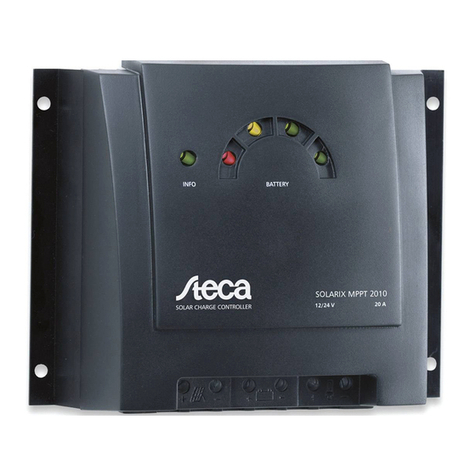
  9. Steca Tarom 4545 User manual

Steca Tarom 4545 User manual

info@splashmonitoring.com www.splashmonitoring.com
Steca Tarom Charge Controller – Ethernet Streambox
Domestic Installation
Hardware summary
Hardware Manufacturer Steca
Hardware Model Tarom 4545
Hardware Size NA
Maximum number of Taroms connected to a single
SPLASH Monitoring STREAMbox 4
List of parts re uired for connecting the hardware to the SPLASH Monitoring
STREAMbox
To enable you to connect the above hardware to SPLASH Monitoring you will need a SPLASH Monitoring
STREAMbox and connection cables, these parts are listed below.
Part description
Part number
Hardware Make / Model As above
SPLASH Monitoring STREAMbox SMSB HW - Hardwired inverter connections
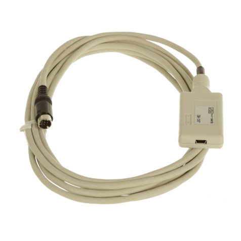
Connection cable STREAMbox to inverter Part numbers Steca PA CAB2
Connection cable STREAMbox to clients router or
LAN Part numbers SM CAT5 1m – 1m CAT5 cable
SM CAT5 2m – 2m CAT5 cable
SM CAT5 5m – 5m CAT5 cable
SM CAT5 10m – 10m CAT5 cable
Optional
External Antenna
High Gain External Antenna and mount
AGM024P
WMO
info@splashmonitoring.com www.splashmonitoring.com
Data Transmission
The following diagram shows the hardware and how the data is transferred from the Tarom to the SPLASH
Monitoring Servers.
info@splashmonitoring.com www.splashmonitoring.com
Installation Guidelines
To ensure long term reliable monitoring;
1. Install the Streamboxand its power supplyawayfrom dailyoperationalareaswhere the hardware could
be accidently turned off such as someone’s desk or work bench.
2. Locate or secure the equipment to prevent it from falling, slipping and becoming disconnected
3. Secure the power cord to the STREAMbox using the supplied “P” cable clamp (see below)
4. Ensure the Ethernet CAT 5 / 6 cables are in good condition with their retaining clips intact and make
sure they are securelyfitted to the equipment by giving them agentle tug.
5. Secure cables to protect them from accidental snagging
6. Do not stretch cablestothe point where anymovement could cause them to become disconnected.
7. The equipment and power supplies will be labelled ‘DO NOT SWITCH OFF’, but you should inform
people with access to the installation area that this equipment should not be turned off; for example
cleaning and maintenance personnel
info@splashmonitoring.com www.splashmonitoring.com
Basic Connectivity - STREAMbox USB Ports:
The USB ports are numbered from 1 to 4, port number 1 is immediately to the left of the SD Card slot, number
2 is immediately to the left of number 1. Number 3 is immediately to the left of the on/off button and number 4 is
immediately to the left of number 3. See below:
ThefirstTaromcanbeconnectedtotheSTREAMboxusingaStecaPACAB2(UARTtoUSB)cableandMUST
be connected to USB port1. See below:
Connect theSTREAMbox toyour LAN using a standardCAT5 or CAT6patch cable.The LAN in your casemay
mean a Router, ADSL Modem, Network Switch, or any other network device connected to the Internet.
info@splashmonitoring.com www.splashmonitoring.com
Setting Up Your Tarom
Set up the Tarom as directed in theTarom User Manual, but in particular you must setthe Open UART/RS232
to ‘On’(Set -> System Settings -> Open UART/RS232 -> On)
Setting Up Your STREAMbox
Unless the STREAMbox has already been configured according to your specifications, it will be configured to
acquire a DHCP IP address from your router or DHCP server. For most domestic applications this will work
without any modification. However, if you do need to change its settings see below for guidance.
Connecting more Taroms
When connecting multiple Taroms to the Streambox, each Tarom is allocated to a physical USB port and it is
importantthattheTarom isnotpluggedintoadifferentUSBport.If youremovetheUSBcable(s)foranyreason,
it is important that they are replaced in the original USB that is came from.
Web Site Setup:
The STREAMBox has already been preconfigured for monitoring the Tarom and the online setup takes only a
few minutes. The Online setup consists of;
1. Registering with SPLASH Monitoring
2. Entering the location and namefor the system
3. Selecting a name for your system
The information is sent from the Tarom to the online servers every 60 seconds, so the STREAMbox scan
frequency is also set to 60 seconds. The scan frequency should not be changed from its preset 60 seconds.
Web Site Values:
The monitoring may indicate error codes from the Tarom, the following arethe error codes.
0 No error
1 Information (module operating normally, but supplementary information available)
2 Warning (module operating normally, but requires attention)
3 Error (module inoperableand requires immediate attention)
4 External temperature sensor defect
5 Tarom has exceeded its maximum operating temperature
7 Battery voltage too low
8 Battery voltage too high
9 Maximum load current exceeded
10 Maximum PV input current exceeded
11 Short circuit on the output load
13 Battery not connected
14 Battery polarity connected incorrectly
15 PV polarity connected incorrectly
19-24 Tarom module error – requires factory attention
26 Battery voltage not detected
29 Date/Time not set
31 Battery voltage detected
34 Over current protection triggered
The monitoring will indicate Mode codes from the Tarom, the following Mode values represents the following
battery charging modes:
1 Float
2 Boost
3 Equalise
4 IUIA
5 NiMH
6 Li-ion
info@splashmonitoring.com www.splashmonitoring.com
Trouble Shooting:
“No Stream Found” on the SM Web site:
This is because the web site hasn’t received any data from the STREAMbox.
•The Tarom can only be interrogated for data if the batteries are connected and have sufficient charge,
or the PV isgenerating sufficient power. Otherwise no data will be produced.
•Allow at least 10 minutes after powering up the STREAMbox before starting your diagnostic checks.
•Check the connections between the STREAMbox and your router and ensure you have a solid green
light at the top left of the RJ45 (LAN) socket and a flashing green light at the top right of the socket.
•No solid green light could indicate: the STREAMbox is switched off (check the power light on the front
of the STREAMbox); or the router isn’t powered up, or the LAN cable isn’t connected to the router; or
the LAN cable is faulty. To eliminate the LAN cable and router, connect the LAN cable to a known
working device likeyour laptopor PC andif you cangeta web session, then the LANconnectivity is OK.
•Check the connection between the STREAMbox and the inverter. Make sure the USBcable is plugged
into the correct physical USB port.
•Try power cycling the STREAMbox – switch it off, wait 5 sec, switch it back on.
•Try logging on to the STREAMbox: enter “splash” in your web browser’s address line, or if your
STREAMbox has a fixed IP address, enter that into your web browser. For instructions on how to use
the STREAMbox’s ‘Web Information Page’ go to http://www.splashmonitoring.com/assets/SM-
STREAMbox-Web-Information-Page.html
•On the Web Information Page check that “si-tarom-usbx (where x=1, 2, 3 or 4)” appears as an entry in
the“OtherAddresses”rowof the“Scanning Information” table.MakesuretheUSB cable ispluggedinto
the same physical USB port as depicted by ‘x’.
•Check that the site’s network firewall is allowing outbound traffic. This is rarely an issue with domestic
routers, but can exist in managed commercial networks. Unless you have someone you can ask (like a
network administrator) a good way to detect this issue is to log onto the STREAMbox and run a
‘Healthcheck’ report. This will give you lots of information including whether the STREAMbox can ‘see’
the internet.
•The STREAMbox is not able to work with a proxy server. If you have a proxy server you will need to
make special arrangements with your network administrator to have the STREAMbox circumnavigateit
by issuing afixed IP address with appropriate privileges.

Other manuals for Tarom 4545

4

Other Steca Controllers manuals

Steca Solsum F User manual

Steca

Steca Solsum F User manual

Steca PR 1010 User manual

Steca

Steca PR 1010 User manual

Steca Tarom 4545 User manual

Steca

Steca Tarom 4545 User manual

Steca TR A301 User manual

Steca

Steca TR A301 User manual

Steca Tarom 4545 User manual

Steca

Steca Tarom 4545 User manual

Steca Suntana User guide

Steca

Steca Suntana User guide

Steca Solsum 6.6F User manual

Steca

Steca Solsum 6.6F User manual

Steca PA RC100 User manual

Steca

Steca PA RC100 User manual

Steca Solarix MPPT 2010 User guide

Steca

Steca Solarix MPPT 2010 User guide

Steca Tarom 4545 User manual

Steca

Steca Tarom 4545 User manual

Steca Solarix MPPT 1010 User manual

Steca

Steca Solarix MPPT 1010 User manual

Steca TR 0704 User manual

Steca

Steca TR 0704 User manual

Steca Solarix 2401 User manual

Steca

Steca Solarix 2401 User manual

Steca PR 1010 User manual

Steca

Steca PR 1010 User manual

Steca Power Tarom 2070 Service manual

Steca

Steca Power Tarom 2070 Service manual

Steca TR A503 TTR U User manual

Steca

Steca TR A503 TTR U User manual

Steca Solarix MPPT 3020 User manual

Steca

Steca Solarix MPPT 3020 User manual

Steca Tarom 4545 User manual

Steca

Steca Tarom 4545 User manual

Popular Controllers manuals by other brands

Chauvet TFX-16CON Technical reference and user's guide

Chauvet

Chauvet TFX-16CON Technical reference and user's guide

Domus Bluebrain Installation and operating instructions

Domus

Domus Bluebrain Installation and operating instructions

Haier QACT17A Installation and operation manual

Haier

Haier QACT17A Installation and operation manual

Bray 73 Series Operation and maintenance manual

Bray

Bray 73 Series Operation and maintenance manual

Siemens SIRIUS 3RW44 manual

Siemens

Siemens SIRIUS 3RW44 manual

CKD ECR Series instruction manual

CKD

CKD ECR Series instruction manual

Reach Technology SLCD+ manual

Reach Technology

Reach Technology SLCD+ manual

ICP DAS USA CAN-8123 Quick start user guide

ICP DAS USA

ICP DAS USA CAN-8123 Quick start user guide

EMKO ESM-3711-CN instruction manual

EMKO

EMKO ESM-3711-CN instruction manual

RMG DFAWLC-044 installation manual

RMG

RMG DFAWLC-044 installation manual

BEA Stanley Dip Switch I Wiring diagram

BEA

BEA Stanley Dip Switch I Wiring diagram

Syba SD-PEX15011 user manual

Syba

Syba SD-PEX15011 user manual

FlowCon FN.1.4 Installation and operation instruction

FlowCon

FlowCon FN.1.4 Installation and operation instruction

Cooper WR-20 manual

Cooper

Cooper WR-20 manual

Henny Penny 10013404 Replacement instructions

Henny Penny

Henny Penny 10013404 Replacement instructions

Danfoss VLT Soft Starter MCD 600 installation guide

Danfoss

Danfoss VLT Soft Starter MCD 600 installation guide

Carel PCOXS user manual

Carel

Carel PCOXS user manual

4O3A SSC-XL manual

4O3A

4O3A SSC-XL manual

manuals.online logo
manuals.online logoBrands
  • About & Mission
  • Contact us
  • Privacy Policy
  • Terms and Conditions

Copyright 2025 Manuals.Online. All Rights Reserved.