If you have a problem, question,
or request, call your local dealer,
or Steelcase Line 1 at
888.STEELCASE (888.783.3522)
for immediate action by people
who want to help you.
(Outside the U.S.A., Canada,
Mexico, Puerto Rico, and the
U.S. Virgin Islands, call:
1.616.247.2500)
Or visit our website
www.steelcase.com
Si vous avez un problème, question,
ou la demande, appellent votre
revendeur local, ou
Ligne 1 de Steelcase à
888.STEELCASE (888,783,3522)
pour l'action immédiate par les
personnes qui veulent vous aider.
(en dehors des Etats-Unis, Canada,
Le Mexique, Porto Rico, et
Les ÉTATS-UNIS. Les Îles Vierges,
appel: 1,616,247,2500)
Ou visiter notre website
www.steelcase.com
Si usted tiene un problema, pregunta,
o la petición, llama a su distribuidor
local, o Línea 1 de Steelcase en
888.STEELCASE (888,783,3522)
para la acción inmediata por la
gente que desea ayudarle.
(fuera de los E.E.U.U., Canadá,
Méjico, Puerto Rico, y Los E.E.U.U..
Islas de la Virgen, llamada:
1,616,247,2500)
O visite nuestro website
www.steelcase.com
©1998 Steelcase Inc.
Rapids Grand, MI 49501
U.S.A.
Les ETATS-UNIS.
Los E.E.U.U.
Printed in U.S.A.
Imprimé aux Etats-Unis.
Impreso en los E.E.U.U.
Installing Simplex and Duplex Receptacles into:
• Series 9000®Structural Panel
• Series 9000®Energy Management Panel and Worksurface
• Avenir®Power Panel
1
of
5
939503122 Rev A
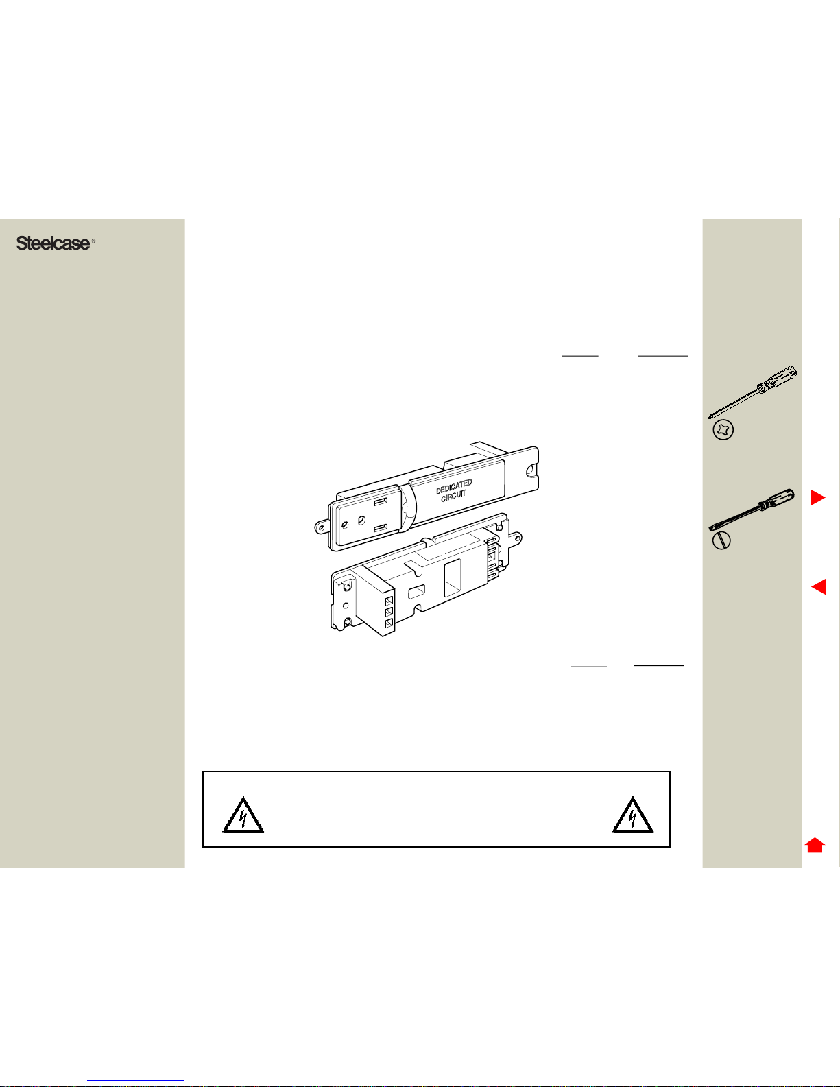
SIMPLEX SHOWN
DEDICATED
CIRCUIT
System Flag Color
• 3-Circuit, Shared Neutral and System Ground (3) Black
• 4-Circuit, 3 with Shared Neutral and System Ground
and 1- Isolated Circuit and Ground (3+D) Black
Optional Wiring Schematics: System Flag Color
• 2-General Circuits with Shared Neutral & System Ground
and 2-Designated circuits with Shared Neutral and Isolated Ground (2+2) Grey
• 3-Separate Circuits - 2 with own Neutral and Isolated Ground,
1 with own Neutral and System Ground (SN) White
• 4-Circuit - 3 with Shared Neutral and Isolated Ground,
1-Circuit with System Ground (3I+1) Tan
WARNING:
ALL ELECTRICAL INSTALLATIONS SHOULD BE PERFORMED BY A
QUALIFIED PERSON IN ACCORDANCE WITH CODES AND
REGULATIONS APPLICABLE AT THE INSTALLATION SITE. CIRCUITS
SHOULD BE CHECKED FOR PROPER VOLTAGES