SteelMax D1 AUTO User manual
The tools of innovation.
15335 E. Freemont Drive, Centennial, CO 80112
1–87STEELMAX, FAX 303–690–9172
www.steelmax.com [email protected]
OPERATOR’S MANUAL
D
D1
1
DRILLING MACHINE
WITH ELECTROMAGNETIC BASE

Contents
1. GENERAL INFORMATION............................................................................................... 3
1.1. Application................................................................................................................. 3
1.2. Technical data............................................................................................................ 3
1.3. Equipment included ................................................................................................... 4
1.4. Dimensions................................................................................................................ 5
1.5. Design ....................................................................................................................... 5
2. SAFETY PRECAUTIONS.................................................................................................. 6
3. STARTUP AND OPERATION........................................................................................... 8
3.1. Installing, removing, and operating the annular cutter................................................ 8
3.2. Installing and removing the cooling system bottle .....................................................10
3.3. Control system of the electromagnetic base holding force ........................................11
3.4. Preparing..................................................................................................................11
3.5. Drilling.......................................................................................................................13
3.6. Replacing the motor brushes ....................................................................................14
4. ACCESSORIES...............................................................................................................15
4.1. Pressure cooling system...........................................................................................15
4.2. Pipe attachment DMP 251 ........................................................................................15
5. WIRING DIAGRAM..........................................................................................................16
6. EXPLODED DRAWINGS AND PARTS LIST....................................................................17
7. DECLARATION OF CONFORMITY.................................................................................21
8. QUALITY CERTIFICATE..................................................................................................22
9. WARRANTY CARD..........................................................................................................23
D1
D1 Operator’s Manual
3
1. GENERAL INFORMATION
1.1. Application
The D1 is a drilling machine with electromagnetic base, designed to drill holes with
diameters of up to 36 mm (1-7/16’’) to a depth of up to 51 mm (2’’) by using annular
cutters.
The electromagnetic base allows the drilling machine to be fixed to ferromagnetic
surfaces with a force that ensures operator safety and proper machine operation.
A safety strap protects the machine from falling in case of a power loss.
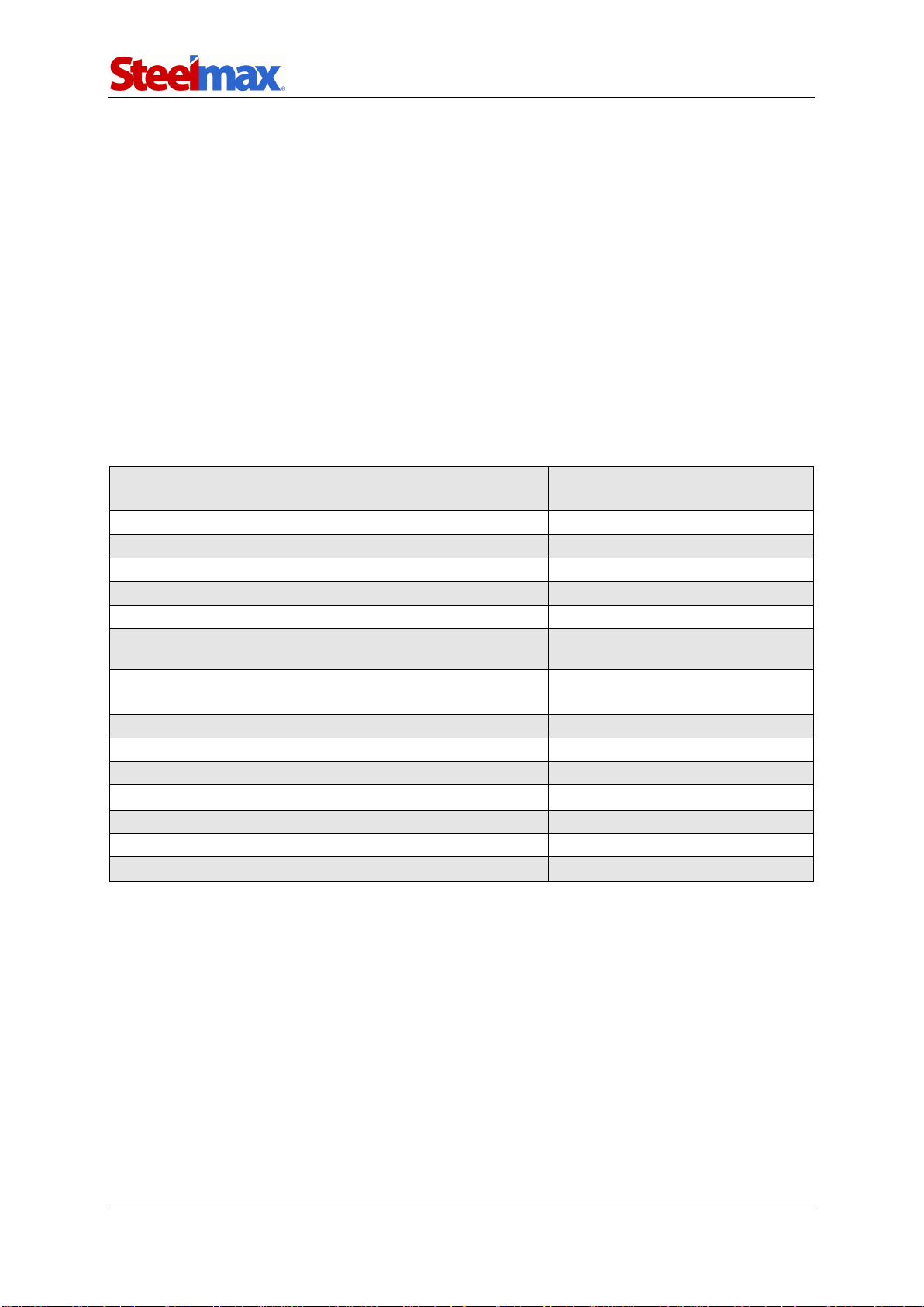
1.2. Technical data
Voltage
1~ 110–120 V, 50–60 Hz
1~ 220–240 V, 50–60 Hz
Total power
1000 W
Motor power
920 W
Tool holder
19 mm Weldon (3/4’’)
Maximum drilling diameter
36 mm (1-7/16’’)
Maximum drilling depth
51 mm (2’’)
Electromagnetic base holding force
(surface with the thickness of 22 mm and roughness Ra= 1.25)
9 000 N (2000 lbs)
Electromagnetic base dimensions
80 mm × 160 mm × 38 mm
3-1/8’’ × 6-5/16’’ × 1-1/2’’
Stroke
70 mm (2-3/4’’)
Rotational speed under load
350 rpm
Minimum workpiece thickness
6 mm (1/4’’)
Protection class
I
Noise level
More than 85 dB
Required ambient temperature
0–40°C (32–104°F)
Weight
10 kg (22 lbs)
D1
D1 Operator’s Manual
4
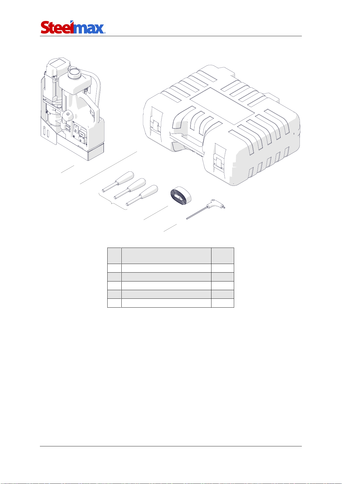
1.3. Equipment included
1
Drilling machine with cooling
system bottle and chip guard
1 unit
2
Plastic box
1 unit
3
Handle
3 units
4
Safety strap
1 unit
5
4 mm hex wrench with handle
1 unit
–
Operator’s Manual
1 unit
1
2
3
4
5

D1
D1 Operator’s Manual
5
1.4. Dimensions
1.5. Design
330 mm (13’’)
314 mm (12-3/8’’)
179 mm (7-1/16’’)
Electromagnetic base
(MAGNET) switch
MOTOR start button
MOTOR stop button
Spindle
with arbor
Carrying handle
Electromagnetic base
Chip guard
Bottle valve lever
Opening for safety strap
Feed shaft
Cooling system bottle
Control panel
Other manuals for D1 AUTO
2
Table of contents
Other SteelMax Drill manuals

SteelMax
SteelMax D300XT User manual

SteelMax
SteelMax D2X User manual

SteelMax
SteelMax SM-D1 User manual

SteelMax
SteelMax D3X RS User manual

SteelMax
SteelMax D1PRO User manual

SteelMax
SteelMax D2X User manual

SteelMax
SteelMax SM-D2 User manual

SteelMax
SteelMax D1 AUTO User manual

SteelMax
SteelMax D4X User manual

SteelMax
SteelMax D250X User manual


