SteelMax D3X R User manual

The tools of innovation.
112 Inverness Circle East Suite F Englewood, CO 80112
1–87STEELMAX, FAX 303–690–9172
www.steelmax.com sales@steelmax.com
OPERATOR’S MANUAL
D
D3
3X
X
R
R/
/L
L
/
/
D
D3
3X
XS
S
R
R/
/L
L
DRILLING MACHINE
WITH ELECTROMAGNETIC BASE

Contents
1. GENERAL INFORMATION............................................................................................... 3
1.1. Application................................................................................................................. 3
1.2. Technical data............................................................................................................ 3
1.3. Design ....................................................................................................................... 4
1.4. D3XS special function................................................................................................ 5
1.5. Equipment included ................................................................................................... 6
2. SAFETY PRECAUTIONS.................................................................................................. 7
3. STARTUP AND OPERATION........................................................................................... 9
3.1. Mounting the arbor (or twist drill)................................................................................ 9
3.2. Mounting and operating the annular cutter................................................................10
3.3. Mounting the screw tap.............................................................................................11
3.4. Mounting the cooling system.....................................................................................12
3.5. Control system of the electromagnetic base holding force ........................................12
3.6. Preparing..................................................................................................................14
3.7. Drilling.......................................................................................................................15
3.8. Tapping.....................................................................................................................16
3.9. Adjusting the slider clearance ...................................................................................17
3.10. Replacing the motor brushes..................................................................................18
4. WIRING DIAGRAM..........................................................................................................19
5. D3X R-L PARTS LIST AND EXPLODED DRAWINGS.....................................................20
6. D3XS R-L PARTS LISTS AND EXPLODED DRAWINGS ................................................26
7. DECLARATION OF CONFORMITY.................................................................................32
8. QUALITY CERTIFICATE..................................................................................................33
9. WARRANTY CARD..........................................................................................................34

D3X R/L / D3XS R/L
D3X R/L / D3XS R/L Operator’s Manual
3
1. GENERAL INFORMATION
1.1. Application
The D3X(S) R/L is adrilling machine with electromagnetic base designed to drill holes
using annular cutters or twist drills. Additionally, the rotation direction switch allows
for direct tapping or tapping with the use of a holder with axial compensation.
The electromagnetic base allows the drilling machine to be fixed to ferromagnetic
surfaces with aforce that ensures user safety and proper machine operation. A safety
chain protects the machine from dropping in the case of a power loss.
1.2. Technical data
Voltage
~ 110–120 V, 50–60 Hz
~ 220–240 V, 50–60 Hz
Total power
1800 W
Motor power
1650 W
Spindle shank
MT3
Tool holder
Weldon 19 mm (0.75’’)
Maximum drilling diameter with annular cutter
12–75 mm (0.47–2.95’’)*
Maximum drilling diameter with twist drill
8–32 mm (0.31–1.26’’)
Maximum drilling depth with annular cutter
76 mm (3’’)
Maximum drilling depth with twist drill
76 mm (3’’)
Maximum tap size
M24 (G3/4’’)
Electromagnetic base holding force
(surface with the thickness of 22 mm and roughness Ra= 1.25)
19 500 N
Electromagnetic base dimensions
110 mm × 220 mm × 56 mm
4.3’’ × 8.7’’ × 2.2’’
Slider stroke
225 mm (8.9’’)
Rotational speed (under load)
80–160 rpm (gear I)
210–420 rpm (gear II)
Minimum workpiece thickness
10 mm (0.39’’)
Protection class
I
Noise level
85 dB
Required ambient temperature
0–40 °C (32–104 °F)
Weight
27 kg (60 lbs)
* Above 60 mm (2.3’’) the UCW-0191-00-00-00-0 arbor is required.

D3X R/L / D3XS R/L
D3X R/L / D3XS R/L Operator’s Manual
4
1.3. Design
Figure 1. D3X R/L design
cooling system bottle
gearbox
spindle with
MT3 shank
motor
spoke handle
carrying handle
control
panel
drilling
machine
body
electromagnetic base
gear
lever
slider
chip
guard
bottle
valve
lever
safety chain lug
arbor
feed
shaft

D3X R/L / D3XS R/L
D3X R/L / D3XS R/L Operator’s Manual
5
Figure 2. Control panel design
1.4. D3XS special function
The D3XS R/L has an ability to turn the upper machine part in the range of ±15°and
to move it out up to 15 mm (0.6’’)without moving the electromagnetic base. To fix the
drilling machine in chosen position, lock the eccentric shaft using the supplied 10 mm
hex wrench.
eccentric shaft
motor START/STOP button
magnet ON/OFF switch
speed adjusting knob
rotation direction switch

D3X R/L / D3XS R/L
D3X R/L / D3XS R/L Operator’s Manual
6
1.5. Equipment included
The D3X(S) R/L is supplied in a metal box with complete standard equipment. The
included equipment consists of:
D3X R/L
D3XS R/L
Drilling machine
1 unit
1 unit
Metal box
1 unit
1 unit
Spoke handle
3 units
3 units
Cooling system
1 unit
1 unit
Arbor with 19 mm (0.75’’) Weldon shank
1 unit
1 unit
Chip guard
1 unit
1 unit
Safety chain
1 unit
1 unit
Drill drift
1 unit
1 unit
2.5 mm hex wrench
1 unit
1 unit
4 mm hex wrench
1 unit
1 unit
5 mm hex wrench
1 unit
1 unit
6 mm hex wrench
1 unit
1 unit
10 mm hex wrench
–
1 unit
8 mm flat wrench
1 unit
1 unit
Operator’s Manual
1 unit
1 unit

D3X R/L / D3XS R/L
D3X R/L / D3XS R/L Operator’s Manual
7
2. SAFETY PRECAUTIONS
1. Before beginning, read this Operator’s Manual and complete proper occupational
safety and health training.
2. The machine must be used only in applications specified in this Operator’s Manual.
3. The machine must be complete and all parts must be genuine and fully operational.
4. Theelectricalsupplyspecificationsmustconformtothosespecifiedontheratingplate.
5. The machine must be plugged into a properly grounded (earthed) socket-outlet. The
electrical supply must be protected with a 16 A fuse for 230 V or a 32 A fuse for
115 V. When used on building sites, supply the machine through an isolation
transformer made in II protection class.
6. Never carry the machine by the cord or pull it to disconnect the plug from the
power outlet as this may damage the power cord and result in electric shock.
7. Transport and position the machine using the carrying handle, with the magnet
switch set to position ‘O’.
8. Untrained bystanders must not be present in the vicinity of the machine.
9. Before beginning, check the condition of the machine and electrical supply, including
the power cord, plug, control panel components, and milling tools.
10. Keep the machine dry. Exposure to rain, snow, or frost is prohibited.
11. Never stay below the machine placed at heights.
12. Keep the work area well lit, clean, and free of obstacles.
13. Mount the annular cutter securely using the set screws. Remove adjusting keys
and wrenches from the work area before connecting the plug to the power outlet.
14. Never use dull or damaged tools.
15. Mount and dismount tools using protective gloves and with the power cord
unplugged from the power outlet.
16. Never use annular cutters without the pilot pin except for establishing incomplete
through holes. Never use arbors without the spring.
17. Never use the machine in the vicinity of flammable liquids or gases, or in explosive
environments.
18. Using the machine on surfaces that are rusty, covered with a thick paint layer,
uneven, or not stiff is prohibited.
19. Do not start operation in the case of excessive slider clearance.

D3X R/L / D3XS R/L
D3X R/L / D3XS R/L Operator’s Manual
8
20. Use the safety chain in all operating positions. The chain must not be loose and
should be fastened to a securely fixed element by catching the chain either on
the lugs or on the carrying handle. Wrap the chain around the workpiece if possible.
21. Before every use, inspect the machine to ensure it is not damaged. Check
whether any part is cracked or improperly fitted. Make sure to maintain proper
conditions that may affect the operation of the machine.
22. Always use eye and hearing protection and protective clothing during operation.
Do not wear loose clothing.
23. Operating on surfaces with thickness lower than 10 mm (0.4’’) is not recommended
as the holding force is significantly reduced.
24. The entire surface of the electromagnetic base bottom must be in full contact with
the workpiece. Before every positioning, wipe the workpiece with coarse-grained
sandpaper.
25. Do not touch moving parts or chips formed during milling. Prevent objects from
being caught in moving parts.
26. After every use, remove metal chips and coolant remainder from the machine.
Do not remove chips with bare hands.
27. Maintain the machine and tools with care. Cover steel parts with a thin grease
layer to protect them against rust when not in use for any extended period.
28. Perform maintenance only with the machine unplugged from the power outlet.
29. Perform repairs only in a service center appointed by the seller.
30. If the machine falls on a hard surface, from height, is wet, or has any other
damage that could affect the technical state of the machine, stop the operation
and immediately send the machine to the service center for inspection and repair.
31. Remove from the worksite and store in a secure and dry location when not in
use, previously removing the tool from the holder.

D3X R/L / D3XS R/L
D3X R/L / D3XS R/L Operator’s Manual
9
3. STARTUP AND OPERATION
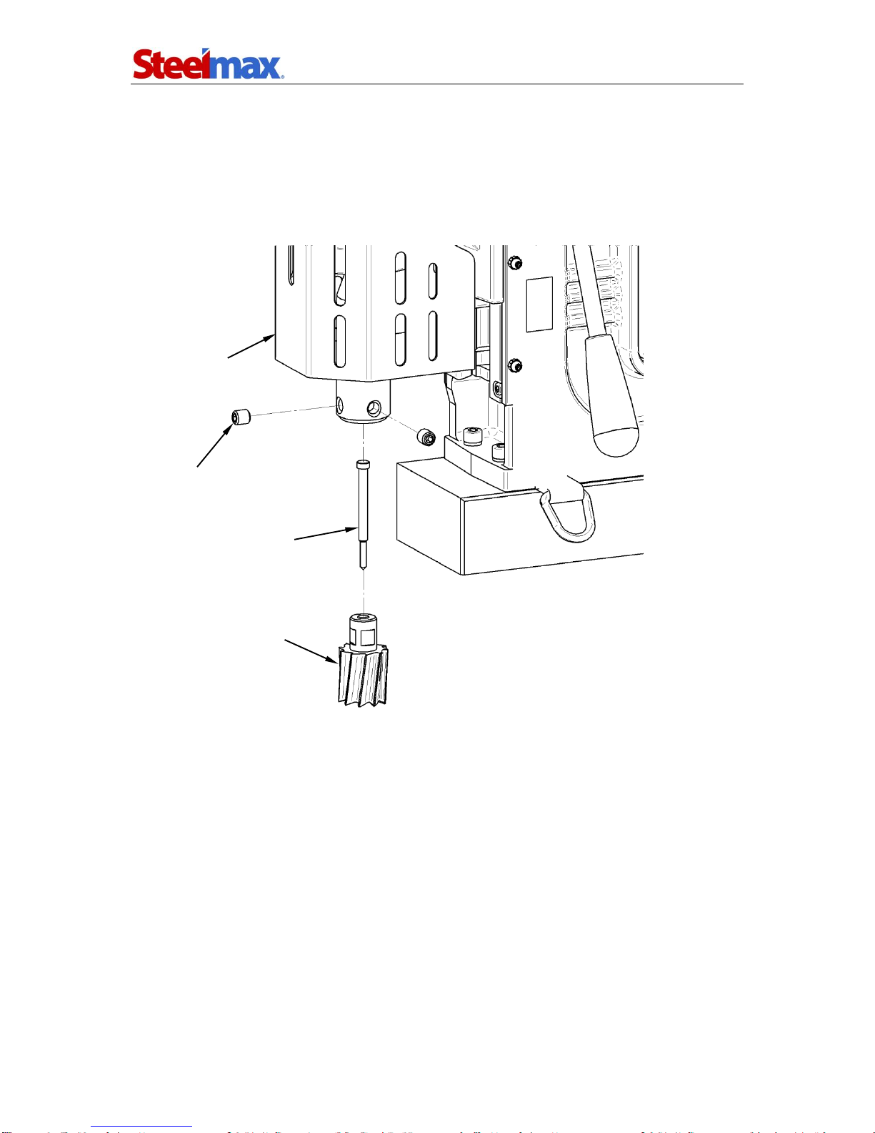
3.1. Mounting the arbor (or twist drill)
The machine allows mounting either the supplied 19 mm (0.75’’) Weldon shank arbor
for fixing an annular cutter or a twist drill into the MT3 spindle shank. Before
proceeding, unplug the power cord from power the outlet. Raise the chip guard and
rotate the spoke handles to raise the slider. Clean the arbor (twist drill) and the inside
of the spindle using a cotton cloth. Wear gloves and insert the arbor (drill) into the
spindle with the fin directed upward and rotate the arbor (drill) to match the fin with
the slot. Then, hit the arbor (drill) from the bottom to mount it into the spindle.
Figure 3. Arbor after mounting
To dismount, rotate the spindle to match the openings in the spindle and gearbox.
Insert the drill drift into the opening above the arbor (drill). Wear gloves and hold the
arbor (drill) with one hand, and hit the drift using a hammer, paying attention not to
damage the arbor (drill). Gently remove the arbor (drill) from the spindle socket and
remove the drill drift.
All safety precautions must be closely observed.
opening
arbor
spindle
gearbox
chip guard
slider
spoke
handle
D3X R/L / D3XS R/L
D3X R/L / D3XS R/L Operator’s Manual
10
3.2. Mounting and operating the annular cutter
Mount the arbor as described before and insert the proper pilot pin into the annular
cutter (Figure 4). Then, wear gloves and mount the cutter into the arbor, aligning the
flats on the cutter shank with the set screws, and tighten the screws with the supplied
5 mm hex wrench. To dismount the cutter, proceed in reverse order.
Figure 4. Mounting the annular cutter
Figure 5 shows how annular cutters operate. As the cutter penetrates the workpiece,
the pilot pin recesses into the arbor and tightens the spring. As a result, after the cutter
goes through the entire thickness, the slug core is expelled from the cutter.
pilot pin
annular cutter
set screw
chip guard

D3X R/L / D3XS R/L
D3X R/L / D3XS R/L Operator’s Manual
11
Figure 5. Annular cutters operation
Annular cutters are designed to establish only through holes shown in Figure 6.
During establishing incomplete through holes the pilot pin must not be used.
Figure 6. Types of holes to establish with annular cutters
3.3. Mounting the screw tap
Unplug the drilling machine from the power outlet and wear gloves. Use the supplied
drill drift to knock out the arbor (drill) from the drilling machine spindle. Mount a holder
for tapping with 1- or 2-axis compensation (not included in standard equipment).
Mount the tap no. 1 into a proper adapter and then mount the adapter into the
compensation holder. Taps with a conical shank can be mounted directly in the
spindle or indirectly using a reducer sleeve with MT3 shank.
slug core
spring
pilot pin
annular cutter
arbor
incomplete through holes
complete through holes

D3X R/L / D3XS R/L
D3X R/L / D3XS R/L Operator’s Manual
12
3.4. Mounting the cooling system
Hang the cooling system on the screws located on the machine side and attach the
tip of the cooling hose to the coupling, as shown in Figure 7.
Figure 7. Mounting the cooling system
3.5. Control system of the electromagnetic base holding force
The D3X(S) drilling machine incorporates a holding force control system to monitor
the adhesion force of the electromagnetic base to the surface. The force value
depends on several factors, such as type, thickness, flatness, and roughness of the
surface, presence of paint, rust or other contaminants, supply voltage fluctuations,
and the wear of the electromagnetic base bottom.
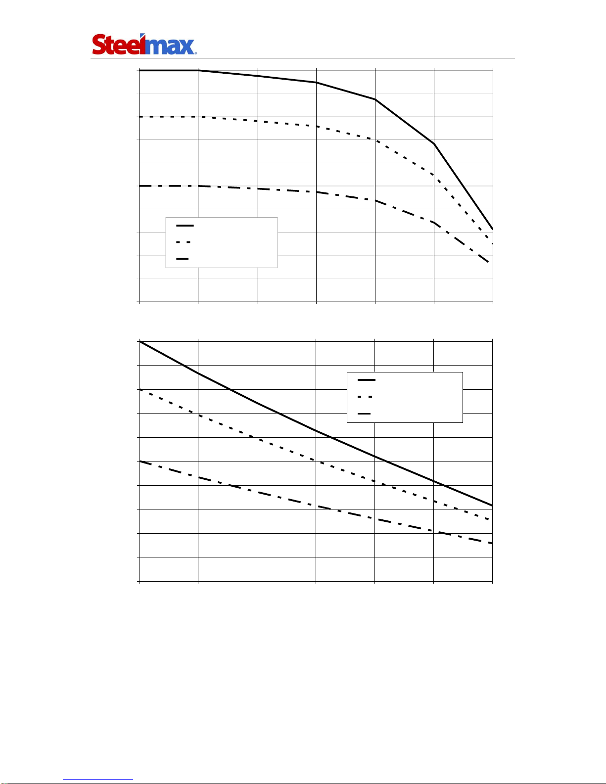
If the holding force falls below a safe operating value (Figure 8), the control system
will not allow the machine to operate. Additionally, the system will prevent the startup
of the motor if the machine is placed on a surface thinner than 5 mm (0.2’’) as such
thickness does not provide sufficient holding force. In such a case, the adhesion force
will be only about 25 % of the force attained on a standard 22 mm (0.87’’) flat plate.
If the motor does not continue operation after the green MOTOR button is
pushed and released, it means that the control circuit is operating properly and
preventing further drilling because of too low adhesion force.
D3X R/L / D3XS R/L
D3X R/L / D3XS R/L Operator’s Manual
13
0
10
20
30
40
50
60
70
80
90
100
25.4 22 19 15.8 12.7 9.5 6.3
Plate thickness [mm]
Holding force [%]
structural steel
heat-treatable steel
tool steel
0
10
20
30
40
50
60
70
80
90
100
00.1 0.2 0.3 0.4 0.5 0.6
Air gap [mm]
Holding force [%]
structural steel
heat-treatable steel
tool steel
Figure 8. Holding force for a sample base in the function of surface thickness and air gap

D3X R/L / D3XS R/L
D3X R/L / D3XS R/L Operator’s Manual
14
3.6. Preparing
Before beginning, clean steel parts, especially the MT3 socket, from grease used to
preserve the machine for storage and transport. The feed shaft can be mounted at
the opposite side of the drilling machine to allow working in places hard to reach or
using the machine by a left-handed person.
Mount a drill, the arbor with an annular cutter, or a holder with a screw tap into
the spindle in the manner described before.
Position the machine on a flat ferromagnetic surface (some types of stainless or
acid-proof steel do not conduct magnetic flux) with the thickness of least 10 mm (0.4’’).
The workpiece must be clean, without rust or paint that decrease the holding force of
the electromagnetic base.
Then, connect the drilling machine to the power outlet and enable the holding
force of the electromagnetic base by toggling the MAGNET switch to position ‘I’.
Mount the chip guard to protect yourself from swarf, and protect the machine with
the supplied safety chain by catching the chain on the carrying handle or on the lugs.
Rotate the spoke handles to place the tip of the drill, pilot pin, or tap above the drilling
(tapping) point.
When working with an annular cutter, install the cooling system. Then, fill the
cooling system bottle with a cutting fluid, slightly loosen the cap, open the valve using
the lever, and initially apply pressure on the pilot pin by rotating the spoke handles
counterclockwise. The fluid should fill the system and should begin flowing from the
inside of the cutter. Do not use pure water as the cutting fluid, however, using
emulsions formed from mixing water and drilling oil is also satisfactory.
The cooling system works by means of gravitation, therefore use
a cooling paste when working in horizontal or inverted positions.

D3X R/L / D3XS R/L
D3X R/L / D3XS R/L Operator’s Manual
15
3.7. Drilling
With the tool mounted, use the gear lever to set the speed range corresponding to
the diameter of the hole to be drilled. Use the following relation among the speed,
diameter, and the type of the tool.
Tool
Hole diameter
Rotational speed
[rpm]
[mm]
[in]
Annular cutter
12–34
0.47–1.34
210–420 (gear II)
35–75
1.38–2.95
80–160 (gear I)
Twist drill
8–17
0.31–0.67
210–420 (gear II)
18–32
0.71–1.26
80–160 (gear I)
Set the rotation direction switch to position ‘R’, and start the motor using the green
MOTOR button. Slowly rotate the spoke handles to lower the cutter (or drill) to the
workpiece and gently begin drilling. Then, use the speed adjusting knob to set aspeed
suitable for given process conditions.
When drilling using annular cutters, accomplish holes in one pass. However,
drilling holes with diameters of 18–32 mm (0.71–1.26’’) using twist drills must be
performed in two passes. In such the case, drill a hole with the diameter of about 70 %
of the final diameter, and then perform the drilling again to finalize the hole to the
anticipated diameter.
When drilling holes deeper than 50 mm (2’’), retract the tool above the workpiece
as often as possible to allow the chips to be expelled from the hole. Additionally,
once the tool is retracted, clean the grooves of the tool using a small brush if they are
clogged. After exceeding 40 mm (1.6’’) of the drilling depth, introduce the cutting fluid
into the milling area manually (from the bottle).
If the operation results in an overload, caused by not sufficient cooling, using dull
tool, or too fast feed in comparison to the tool diameter, the machine will automatically
stop. In such a case, to restart the machine, press the red MOTOR button, retract the
tool from the workpiece, and then press the green MOTOR button (the electromagnetic
base must remain powered).
Once the hole is accomplished, retract the tool from the workpiece, stop the
motor using the red MOTOR button, and disable the electromagnetic base by toggling
the MAGNET switch to position ‘O’.
When the annular cutter goes through the material, the slug core
is expelled from the cutter with a significant force.

D3X R/L / D3XS R/L
D3X R/L / D3XS R/L Operator’s Manual
16
To improve lubrication, after the work is finished and the motor is stopped toggle
the gear to the opposite position (for example: from gear II to I) and run the drilling
machine for awhile without load. Then, stop the motor and disable the electromagnetic
base, unplug the power cord from the power outlet, and clean metal chips and coolant
remainder from the machine. Tighten the bottle cap of the cooling system, close the
valve, and press the pilot pin to expel the coolant remaining within the system. Before
putting the drilling machine into the tool box, disassemble the cooling system and
remove the tool from the holder using gloves.
3.8. Tapping
Position the machine in such a way to place the tap no. 1 above the hole with proper
diameter. With the hole diameter being too low, tapping may be impossible because
of excessive milling resistance and insufficient motor power.
Select the first gear using the gear lever and set the rotation direction switch to
position ‘R’. Spread grease on the working part of the tap to prevent seizure and
extend durability. Then, start the motor with the green MOTOR button and slowly
rotate the spoke handles to lower the tap to the workpiece and begin tapping. Once
tapping with the tap no. 1 is finished, stop the motor using the red MOTOR button
and set the rotation direction switch to position ‘L’. Then, press and hold the green
MOTOR button to retract the tap from the hole, and release the button once the tap is
retracted.
At this stage, replace the tap no. 1 with the tap no. 3 and perform the tapping
again, proceeding as described before. To improve lubrication, after the work is
finished and the motor is stopped, switch to gear II and run the drilling machine for
a while without load. Then, stop the motor and disable the electromagnetic base, and
unplug the power cord from the power outlet.
D3X R/L / D3XS R/L
D3X R/L / D3XS R/L Operator’s Manual
17
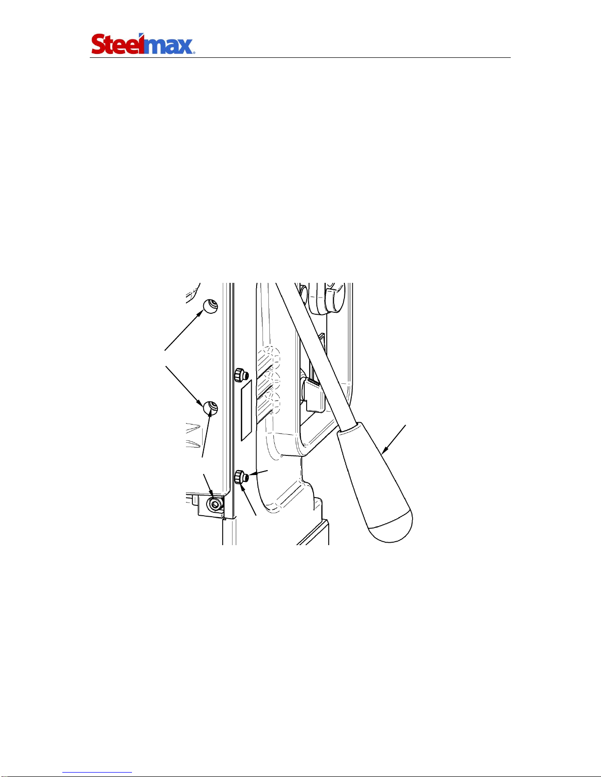
3.9. Adjusting the slider clearance
Check the slider clearance every 50 operational hours or more often as the clearance
significantly influences the quality of drilled holes. The clearance is suitable if the
slider moves smoothly and does not drop under its own weight.
To adjust the clearance, loosen the mounting screws using the supplied 4 mm
hex wrench. Access the screws through the slider holes (Figure 9) by positioning the
slider at the appropriate level using the spoke handles. With all the screws loosened,
move the slider up and down several times and tighten the central screw, then the
adjacent screws, and eventually the utmost screws. Next, tighten the set screws until
noticeable resistance, lock them using the supplied 2.5 mm hex wrench and tighten
the nuts with the 8 mm flat wrench.
Figure 9. Adjusting the slider clearance
slider openings
mounting screws
spoke handle
set
screw
nut
D3X R/L / D3XS R/L
D3X R/L / D3XS R/L Operator’s Manual
18
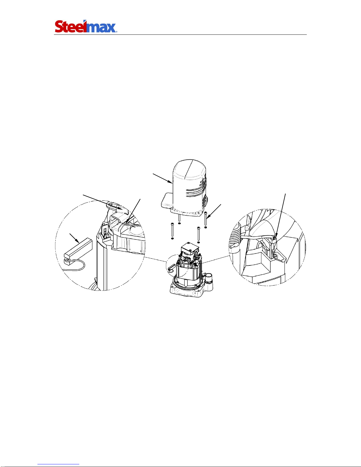
3.10. Replacing the motor brushes
Check the condition of the carbon brushes every 100 operational hours. If the length
of the brushes is less than 5mm (0.2’’), replace them with new ones. To do this, unplug
the power cord from the power outlet, unscrew four screws mounting the motor cover
and gently remove the cover (Figure 10). Proceed with caution paying attention to the
grounding wire connected to the cover. Then, press the center of the brush wire
connector to unlock it and remove the connector. Unbend the spring, put it on the top
of the brush holder, and gently remove the brush. Proceed as described also for the
second brush located at the opposite side of the motor. To mount brushes, proceed
in reverse order. After the replacement, run the motor without load for 20 minutes.
Figure 10. Replacing the brushes
screws
motor cover
brush wire connector
pressing spring
brush
brush holder

D3X R/L / D3XS R/L
D3X R/L / D3XS R/L Operator’s Manual
19
4. WIRING DIAGRAM

D3X R/L / D3XS R/L
D3X R/L / D3XS R/L Operator’s Manual
20
5. D3X R-L PARTS LIST AND EXPLODED DRAWINGS
13
9
3
11 12
1
8
20
15
10
19
14
16
2
6
17
4
5
18
ITEM
PART NUMBER
DESCRIPTION
Q-TY
1
KLN-0103-00-00-00-0
WEDGE MT3
1
2
UCW-0173-00-00-00-0
ARBOR ASSY AMT3-U19/3-3
1
3
LNC-0223-00-01-00-0
SAFETY CHAIN
1
4
UKL-0399-11-00-00-0
COOLING SYSTEM
1
5
DZW-0400-07-00-00-0
SPOKE HANDLE WITH KNOB
3
6
SKR-0400-12-00-00-1
METAL CASE
1
8
KLC-000003
8 MM FLAT WRENCH
1
9
KLC-000037
5 MM HEX WRENCH WITH HANDLE
1
10
OPK-000001
PLASTIC BOX
1
11
KLC-000005
2.5 MM HEX WRENCH
1
12
KLC-000007
4 MM HEX WRENCH
1
13
KLC-000009
6 MM HEX WRENCH
1
14
PDK-0139-00-04-00-0
WASHER D=18.8x10x1
1
15
USZ-0140-05-04-00-0
SEAL
1
16
WYP-0154-00-02-00-0
PLUNGER
1
17
SPR-0154-00-03-00-0
SPRING 1.6x12.4x159
1
18
KRP-0173-00-01-00-0
ARBOR BODY
1
19
PRS-000009
INTERNAL RETAINING RING 19w
1
20
WKR-000032
HEX SOCKET SET SCREW WITH FLAT POINT M10x10
2
This manual suits for next models
3
Table of contents
Other SteelMax Drill manuals

SteelMax
SteelMax D4X User manual

SteelMax
SteelMax D1PRO User manual

SteelMax
SteelMax D1 AUTO User manual

SteelMax
SteelMax D3X RS User manual

SteelMax
SteelMax SM-D1 User manual

SteelMax
SteelMax D200XT User manual

SteelMax
SteelMax D1 AUTO User manual

SteelMax
SteelMax SM-D1 User manual

SteelMax
SteelMax SM-D2 User manual

SteelMax
SteelMax D4X User manual


Popular Drill manuals by other brands


Central Pneumatic
Central Pneumatic 46524 Assembly and operating instructions

Worx Nitro
Worx Nitro WX130L.X manual

Toolshop
Toolshop 241-9826 Operator's manual

BLACK DECKER
BLACK DECKER BDCHD12 manual

MasterForce
MasterForce 241-0401 Operator's manual

BlackBull
BlackBull DP5UL Assembly & operating instructions