SteelMax SM-D1 User manual

Steelmax Tools LLC 6200 S Troy Circle Suite 110 Centennial, CO 80111
1-87Steelmax www.steelmax.com sales@steelmax.com
® D1
Portable Magnetic Drilling Machine
OPERATOR’S MANUAL
MODEL #SM-D1
Serial # _______________________________ Date of Purchase ______________________

D1
- 2 -
D1 9/2011 Operators Manual for Drilling Machine
TABLE OF CONTENTS
1. GENERAL INFORMATION ........................................................................................................- 3 -
2. TECHNICAL DATA.....................................................................................................................- 4 -
3. STANDARD EQUIPMENT..........................................................................................................- 5 -
4. GENERAL SAFETY ADVICE.....................................................................................................- 5 -
5. START UP AND OPERATION ...................................................................................................- 7 -
6. MAINTENANCE AND SERVICE..............................................................................................- 13 -
7. PARTS LIST / EXPLODED VIEWS..........................................................................................- 15 -
8. ELECTRICAL DIAGRAMS .......................................................................................................- 24 -
9. DECLARATION OF CONFORMITY.........................................................................................- 26 -
10.MACHINE’S TEST CERTIFICATE...........................................................................................- 27 -
11.WARRANTY CARD..................................................................................................................- 28 -
12.ANNULAR CUTTERS...............................................................................................................- 29 -
Steelmax Tools LLC
Tel · 303.690.9146 or Fax · 303.690.9172
6200 S. Troy Circle. Suite 110. Centennial, CO 80111
email · sales@steelmax.com / web · steelmax.com

D1
- 3 -
D1 9/2011 Operators Manual for Drilling Machine
1. GENERAL INFORMATION
Portable drilling machines with electromagnetic bases are fast becoming very
universal power tools not only at steel fabricating workshops or steel building sites
but also at every factory maintenance workshop, truck manufacture & repair
company, military equipment service, onboard ship maintenance shop etc.
Full advantages of electromagnetic drilling machines can be achieved only
with optimal tooling. Annular cutters are designed and manufactured specifically for
use with these machines and offer a whole range of advantages such as 4 inch
diameter holes through more than 2 inch steel, in one pass and with precision not
otherwise attainable without heavy stationary equipment.
The D1 drill is capable of milling 35 mm (1-3/8 inch) holes through 2 inch steel.
The D1 is equipped with a powerful new generation, low heat electromagnet with
Condensed Magnetic Flux (CMF) and with field control system.
Before you start work with the machine, please read these
instructions carefully. Take special note of safety recommendations.
D1
- 4 -
D1 9/2011 Operators Manual for Drilling Machine
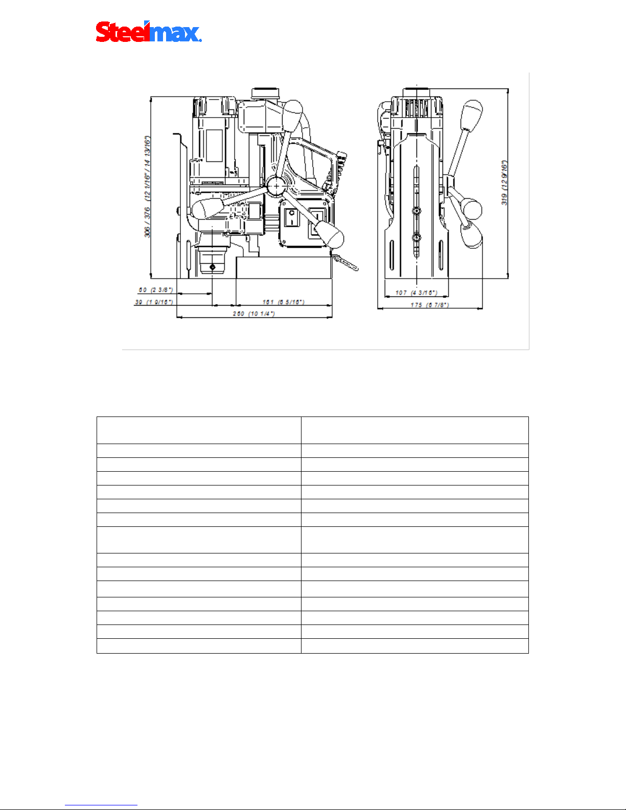
2. TECHNICAL DATA
Power supply
□220-240 V AC/ 50/60 Hz
□120 V AC/ 50/60 Hz
Power required
1000 W
Motor power
920 W
Tool holder
3/4” Weldon, 19,05 mm/
Max. milling cutter diameter
1-3/8", 35 mm
Max. milling/drilling depth
2” , 51 mm
Insulation Class
First
Standard adhesive force of
electromagnet on1” plate
9500 N
Slide stroke
2-3/4", 70 mm
Machine speeds /under load/
350 rpm
Electromagnetic base 3-18 x 6-5/16 x 1-7/16", 80x160x36.5 mm
Length of the power cord
10 ft, 3.0 m
Total weight
22 lbs, 10 kg
Noise level
85 dB
Surrounding temperature
0
°
C – 40
°
C

D1
- 5 -
D1 9/2011 Operators Manual for Drilling Machine
OPERATING INSTRUCTIONS (BEFORE YOU BEGIN)
Remove all contents from packaging and inspect to ensure no damage was incurred during shipping.
Your SM-D1 package should include the following:
3. STANDARD EQUIPMENT
The D1 comes in a set which consists of:
metal box
1 pc
drilling machine
1 pc
cooling system
1 pc
4 mm Allen wrench
1 pc
spoke handles
3 pcs
safety chain with snap hook
1 pc
operator’s manual
1 pc
chip guard
1 pc
4. GENERAL SAFETY ADVICE
The D1 drilling machine must not be used when:
1. The operator has not read the Operator’s Manual.
2. The work to be done is not in agreement with the recommendations in this
Manual.
3. Drilling machine is not complete or has been repaired with non-original parts.
4. Power supply parameters do not conform to those stated on the motor’s plate.
5. Machines operator has not checked condition of the drilling machine, condition of
power cable, control panel or cutter.
6. Power supply socket is not equipped with a protection circuit.
7. Machine is not secured with safety chain as a protection from falling down,
especially when used at heights or in vertical or upside-down positions.
8. Bystanders are present in the immediate vicinity of machine.
Important rules of safe use of drilling machine
1) Before attempting to work with the machine check condition of power cord and
plug.
2) The drilling machine should be connected to an installation equipped with
protection circuit (neutral or ground) and protected with a 16 A fuse for 220V
D1
- 6 -
D1 9/2011 Operators Manual for Drilling Machine
and 32 A fuse for 120V.When used on building sites, it must be supplied
through a separation transformer made in the second class of protection.
3) Machine can be used outdoors, but is not weatherproof. Do not expose to rain,
snow or frost.
4) Machine should not be used on: rusty surfaces, steel plates with thick covered
with paint, uneven surfaces or next to a welding machine.
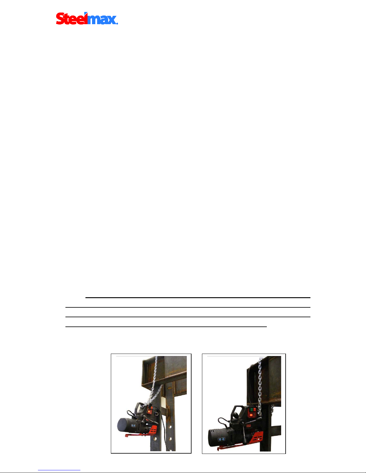
5) In all cases, always use a safety chain/strap (see drawing 1). The safety chain
should be tight! To avoid this situation the safety chain should be wrapped
around the element it is hooked to.
6) Do not use the machine in explosion hazard zones.
7) Do not start work if the machine has excessive play on guide slides.
8) Always wear safety goggles and ear protection.
9) Do not remove metal chips with bare hands.
10) Do not touch the spindle and the cutter during work.
11) Tools must be fastened firmly. When an annular cutter is used, check before
start of work to ensure tool holding screws are tight.
12) Do not use dull or damaged tools.
13) Do not use annular cutter without pilots, and arbors without ejection spring.
14) Use tools recommended in Operator’s Manual only.
15) After use, always clean metal chips and coolant from drilling machine.
16) Always unplug the machine from the power supply before doing any work on the
machine.
17) In the event that the machine falls on a hard surface, from a height, is wet or is
subjected to other unfortunate events that could affect its technical state - work
should be terminated immediately and the machine should be sent to service for
inspection as soon as possible.
Do not use D1 drill on steel thinner than (3/8”, 10 mm). On thin steel
(less than 3/8” (10 mm)) magnet’s adhesive power is significantly reduced
which can cause machines failure or individuals injury. The entire surface of
the electromagnetic base should be located on the work piece!
It is recommended that the surface under the electromagnetic base be
sanded down with abrasive paper, before positioning the machine!
D1
- 7 -
D1 9/2011 Operators Manual for Drilling Machine
5. START UP AND OPERATION
5.1 Cutters and optional equipment features.
This drilling machine’s spindle has a Weldon Shank type socket 3/4” or
19,05 mm and is specifically designed for use with annular cutters.
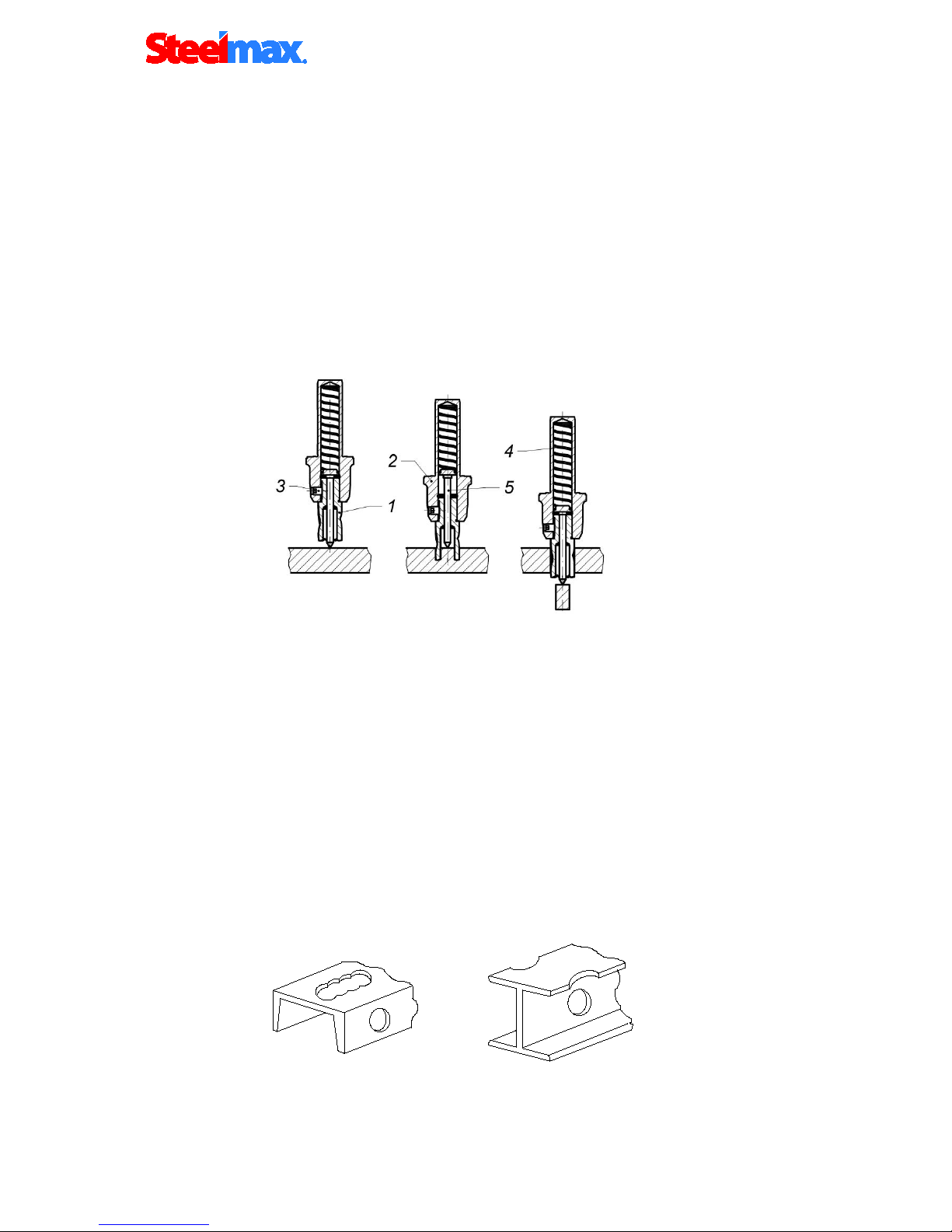
Annular cutter (1) is placed inside arbor body (2) and is fastened with screws
(3). While fastening the cutter in the socket, be aware that screws should be screwed
tight so that they will not come unscrewed. It is important to position the cutter in
relation to the socket in such a way that fixing flats on the cutter shank are positioned
opposite to the fixing screws (3). Both fastening screws(3), should be used to fasten
the cutter. Pilot (5) is located inside the cutter. It makes it easier to position milling
cutter over center of a planned hole. During drilling, as the cutter goes into the steel,
the pilot moves back into the arbor body and tightens discharge spring (4). That
spring ejects slug which is a by-product of milling a hole with an annular cutter.
Drawing 2.
Principle of milling cutter’s work
Drawing 3.
A few types of holes that can be done with a milling cutter
Drawing 1.
Examples how safety chain should be fastened.

D1
- 8 -
D1 9/2011 Operators Manual for Drilling Machine
Basically annular cutters are designed to make through holes. On occasions
when there is a need for an overlapping hole the pilot should not be used.
5.1.1 Installing and uninstalling the annular cutter
Annular cutter installation and uninstallation should be carried out
when the machine is turned off and the power cord is unplugged!
Installing the annular cutter:
1. Raise the drive and the slide (2) up using the lever (3);
2. Raise the guard (1) to the maximum height in order to attain access to the
screws (5) in the spindle (4);
3. Insert the appropriate type of pilot (6) into the annular cutter (7);
4. Position the annular cutter (7) with the cutter facing up, so that the flat sides of
the cutter are facing the screws (5)
5. Put the annular cutter (7) into the spindle socket (4);
6. Tighten both screws securely (5).
Uninstalling the annular cutter:
1. Raise the drive and the slide (2) up using the lever (3);
2. Raise the guard (1) to the maximum in order to attain access to the spindle (4)
screws (5).
3. Loosen the screws (5);
4. Remove the annular cutter (7) and the pilot (6) from the spindle socket (4).
D1
- 9 -
D1 9/2011 Operators Manual for Drilling Machine
5.2 Operating instructions
The machine is supplied in a metal box. Check if all parts listed in paragraph 3
are included. Steel elements of the drilling machine are protected for transit and
storing with grease film. Before first start up of the machine all grease should be
removed. Before each use all spoke handles should be screwed into pinion.
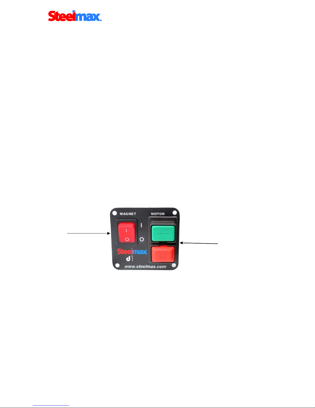
Control panel,
Control panel includes:
- 2-position main switch (01),
- START-STOP button (02),
a) In order to start the machine press the main switch (01) on “I“ button. Now you
can start the motor by pressing green button „ I” (02).
b) Stop the motor by pushing the red button, “O” (then the motor is switched OFF,
but the electromagnetic base is still ON) (02).
c) To move machine into next drilling spot, stop the motor as described above
and push the magnet switch (01) to the position “O”.
Drawing 4.
Control panel
01
02

D1
- 10 -
D1 9/2011 Operators Manual for Drilling Machine
CAUTION: READ THE WHOLE INSTRUCTIONS MANUAL
BEFORE ATTEMPTING TO START UP
5.3 Before you cut
Before positioning the machine on the work piece, always make sure that:
-work piece is made of steel;
-thickness of work piece is at least 3/8” (10 mm)
-surface of steel under the magnet is flat
-wipe, brush or sand down clean surface where you intended to place the
drilling machine, so that you remove rust, paint, dirt etc which would reduce adhesive
power of the electromagnetic base.
Install drill bit, annular cutter or other tooling such as tap or reamer in the machine
before plugging it in. Then plug it in (see paragraph 3) and position where you wish
to use it. Place the machine so that the tool is over the center of the hole you intend
to make and turn the magnetic base ON.
Prior to use always make sure that the machine is secured from falling
down with original chain (as described in paragraph 4 “Important rules of safe
use of drilling machine”).
5.4 Cutting
- Cooling and lubricant fluid commercially available in concentrated form are
recommended for cooling twist drill bits and annular cutters.
It’s allowed to use emulsions formed from a mixture of water and drilling oil.
Do not use clean water as the liquid cooling and lubricant.
The cooling system is an integral part of the machine and should always be used.
(see point 5.7)
Warning: The cooling system can only be used when drilling machine is
in vertical position. In other positions additional external source of cooling
should be used, for example: a coolant bottle with a long nozzle, or a paste
type lubricant.
-Check to make sure the cooling system is working. Open coolant reservoir’s
valve and apply pressure on the pilot by turning spokes counter clockwise. As the
pilot starts to sink into the cutter, cooling liquid should start to run down cutters inner
wall. If there is no liquid flowing down, check to make sure valve is fully opened. It
may take a few seconds for cooling liquid to fill the whole system.
-Turn the motor on.

D1
- 11 -
D1 9/2011 Operators Manual for Drilling Machine
Bring the cutter gently into contact with the work piece and slowly start to
apply pressure on the cutter.
Making a hole with a milling cutter should ideally be done in one pass. It
makes the cutter work better and easier to eject the slug after the hole is completed.
If you experience slugs getting stuck inside a cutter after hole is complete, try to
reduce pressure on the cutter or use a different coolant. Do not allow excessive swarf
build up around the cutter and arbor.
WARNING: when the milling cutter goes through the material the
slug can be pushed out, often with considerable force.
Pay attention to avoid injury.
-After a hole is made the cutter should be withdrawn back and both the motor
and the electromagnet should be switched OFF.
-When work with the machine is finished, the power cord should be
disconnected from the power source. Clean the swarf, coolant, etc, from the
machine. The cutter should be removed and cleaned.
5.5. How to use the special functions
There are many causes which can reduce magnet holding force. These can be:
insufficient work piece thickness, paint coating, rust or dirt, uneven and rough
surfaces, extensive wear of the magnets bottom surface etc.
If after turning the drills electromagnet ON, the motor starts, but then stops
when you remove your finger from the ‘ON’ button, this can be caused by the
machines safety system, which has detected insufficient magnet holding
power. You can make the motor run by continuing to hold the green Start “I”
button. To eliminate this situation, it is necessary to improve magnetic
properties of the work piece or recondition the magnetic base.
Electromagnets dual clamping system.
Machines magnetic base is supplied with a half of normal voltage every time the
magnet is On but the motor is OFF.
This feature reduces power supply consumption and extends magnets durability.
Full power of machines magnet ( 9500 N.) is obtained a 1.5 second after the motor is
switched ON

D1
- 12 -
D1 9/2011 Operators Manual for Drilling Machine
5.6 The overload protection.
The drilling machine is equipped with overload protection system. If machine is
working close to overload limit it can be switched off, automatically.
In this case the operator should turn it on again.
5.7 Installing and uninstalling the cooling system
Installing the cooling system:
a) Place the machine in the vertical position,
b) Raise the drive and the slide up by using the lever,
c) Attach the cooling system,
d) Install the end of the cooling hose (2) on the connection end (4) in the reducer.
Before starting the machine:
•Remove the bottle’s cap,
•Fill it with cooling lubricant,
•Replace bottle cap.
Upon completion of the above steps, the bottle cap should be loosened by 1/3 of a
turn to allow airflow into bottle. Then turn on the valve (3) to start liquid flowing to the
hose, after which the machine can be started (see II pt. 3)
After completing work, one must remember to tighten the bottle cap and turn
off the valve (3) (to prevent liquid from leaking when the machine is not in use) and
remove the cooling system before placing the machine in the box.

D1
- 13 -
D1 9/2011 Operators Manual for Drilling Machine
Uninstalling the cooling system:
a) Place the machine in the vertical position,
b) Raise the drive and the slide up by using the lever,
c) Remove the end of the cooling hose (2) on the connection end (4) in the reducer,
d) Remove the cooling system.
6. MAINTENANCE AND SERVICE
-The D1 machine is equipped with a maintenance free system for
adjustment of guide slides.
-Check condition of carbon brushes after every 100 hours of work.
Replacement of brushes is possible without removal of motor unit from the unit. (see
point 6.1) Other repair work should be done only by authorized service points,
appointed by distributor.
-To prevent the machine from rusting (especially when used outdoors) all steel
parts should be covered with thin layer of grease film.
WARNING: The safety strap and web must be replaced after
every occurrence when machine came loose from steel and hung or
pulled on the strap and web.
If work piece thickness is less than 3/16” (5mm), the magnetic adhesion detection
system will not allow the motor to start. The same system will turn the motor OFF
after even a slight movement of the magnetic base.
Caution: In the case that the machine falls on a hard surface,
from a height, is wet or is subjected to other unfortunate events that
could affect its technical state - work should be terminated
immediately and the machine should be sent to service for
inspection as soon as possible.

D1
- 14 -
D1 9/2011 Operators Manual for Drilling Machine
6.1 Replacement of motor brushes
The carbon brushes of the D1 drill should be monitored every 100 working
hours.
Replacement of motor brushes should be carried out when the machine
is switched off and with the power cord unplugged!
1. Loosen 4 4x19 screws (1), fastening the motor cover (2).
2. Remove the motor cover (2).
3. Loosen 3x13 screws (3), fastening the pressure plate (4) of the brush holder
(5).
4. Remove the brush holder pressure plate (4).
5. Be careful not to remove the brush conduit, lightly raise the brush holder (5)
and remove the motor brush (6).
6. Monitor brush length - If the length is less than 5 mm, it must be exchanged
for a new brush.
7. Carry out all actions in reverse, in order to install the motor.
Caution: During the installation of the brush-holder (5), pay attention to the
placement of conductors under the brush-holder - they must be placed in a special
recess made in the motor housing.
After replacement of new brushes, they must be ground in for about 20 minutes
on the idle gear. Replacement of motor brushes is possible without removing the
drive from the drill.

D1
- 15 -
D1 9/2011 Operators Manual for Drilling Machine
7. Parts List / Exploded Views
WRT-0440-24-10-00-0 DRILLING MACHINE Steelmax D1 /115V
WRT-0440-24-20-00-0 DRILLING MACHINE Steelmax D1 /230V
ITEM PART NUMBER VERSION DESCRIPTION QTY
1
STJ-0440-01-00-00-1
2011
FRAME ASSEMBLY
1
2
RDK-0440-02-00-00-1
1555
GEARBOX ASSEMBLY
1
3
SLN-0440-03-00-00-3
2012
MOTOR ASSY/120V
1
3
SLN-0440-03-00-00-5
2013
MOTOR ASSY/230V
1
4
OSL-0440-04-00-00-0
2486
GUARD ASSY,
1
5
UKL-0440-05-00-00-1
COOLANT BOTTLE ASSY,
1
6
PNL-0272-04-00-00-4
2015
CONTROL PANEL ASSEMBLY /120V,
1
6
PNL-0272-04-00-00-5
2014
CONTROL PANEL ASSEMBLY /230V,
1
SZN-0075-00-51-00-5
POWER CORD 120V 3x2,08
1
7.4
DLW-000007
STRAIN RIELIEF PG11
1
7
SZN-0212-10-02-00-2
POWER CORD 230V 3x1,5
1
7.4
DLW-000007
STRAIN RIELIEF PG11
1
8
DZW-0212-12-00-00-0
SPOKE HANDLE INCLUDING KNOB (ASSY),
3
9
TLJ-0399-06-00-00-0
LOWER SLEEVE,
2
10
SPR-000030
PUSH SPRING,
2
11
PDK-000151
NYLON WASHER SR1940,
4
12
WKR-000395
SOCKET BUTTON HEAD CAP SCREW WITH FLANGE M5x20,
2
13
WKR-000113
CROSS RECESSED RAISED COUNTERSUNK HEAD SCREW M4x16
1
14
PDK-000060
SPRING WASHER-4.3
1
15
NKR-000013
HEX NUT M4
2
16
PDK-000043
SPRING WASHER-4.1
1
17
SRB-000122
HEX. SOCKET BOLT M-6X35
2
18
SRB-000119
HEX. SOCKET BOLT M6x30
2
19
PDK-000161
SPRING WASHER 3,7
4
20
WKR-000415
CROSS RECESSED PAN HEAD TAPPING SCREW 3,5x13
4
21
WKR-000302
SCREW FOR PLASTIC M5x30
3
22
WKR-000237
CROSS RECESSED CHEESE HEAD SCREW M5x50
1
25*
ZST-0440-25-00-00-0
2019
EQUIPMENT SET
1
25.1*
KLC-000007
HEX. WRENCH S=4
1
25.2*
LNC-0129-80-01-00-0
SAFETY CHAIN
1
25.4*
INS-0239-48-00-00-3
SERVICE MANUAL
1
26*
SKR-0440-12-00-00-0
1670
METAL BOX
1
27*
SMR-000001
GREASE LUBRIPLATE, GR-132
0,055kg
28*
NKL-0440-15-08-04-0
LABEL FOR SIDE OF METAL BOX - small
4
29*
NKL-0440-15-08-05-0
LABEL FOR LID OF METAL BOX - big
1
*not shown on the drawing

D1
- 16 -
D1 9/2011 Operators Manual for Drilling Machine
D1
- 17 -
D1 9/2011 Operators Manual for Drilling Machine
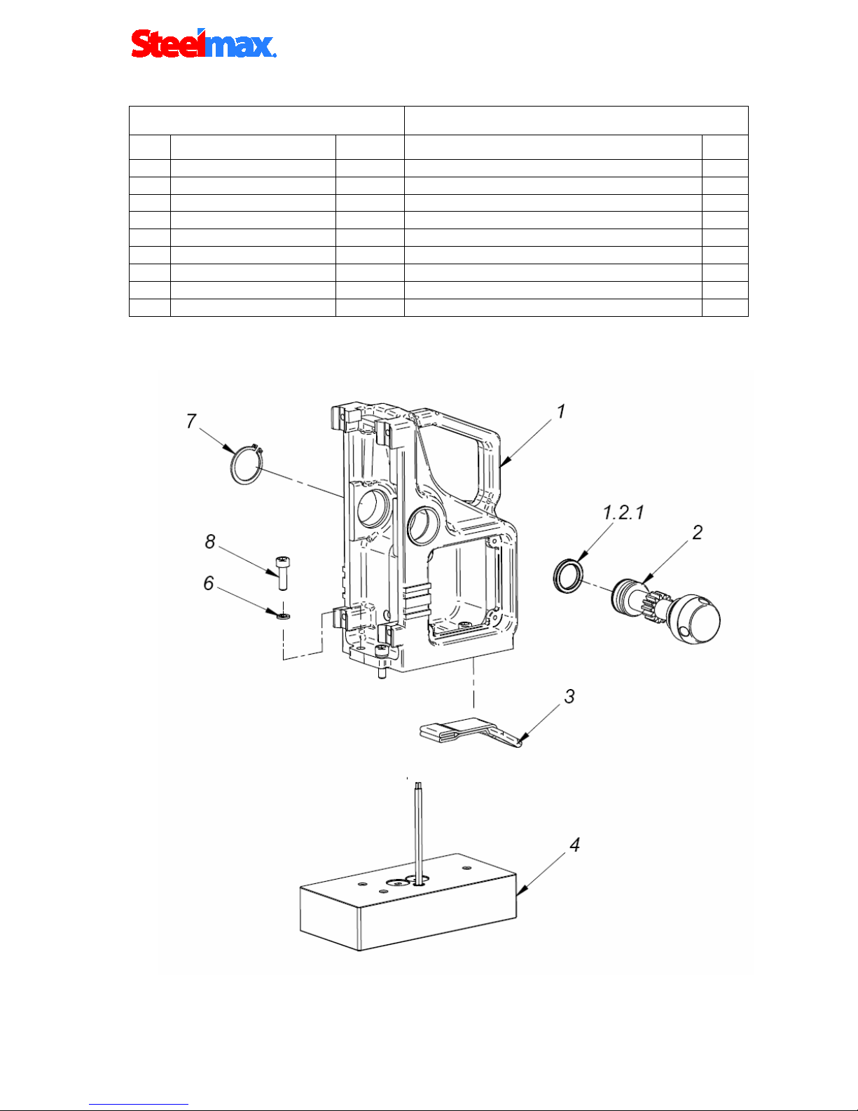
STJ-0440-01-00-00-1 FRAME ASSEMBLY
ITEM PART NUMBER VERSION DESCRIPTION QTY
1.1
KRP-0440-01-01-00-1
1549
MAIN BODY ASSY
1
1.2
WLK-0440-01-02-00-0
PINION SHAFT ASSY z14
1
1.2.1
USZ-000015
SEAL QUAD-RING 20,22x3,53
2
1.3
PAS-0272-01-03-00-0
D-RING STRAP
1
1.4
PDS-0378-02-00-00-1
1063
ELECTROMAGNETIC BASE,
1
1.6
PDK-000048
SPRING WASHER 6,1
3
1.7
PRS-000019
EXTERNALE RETAINING RING 28z
1
1.8
SRB-000113
HEX. SOCKET BOLT M6x20
3
1.9*
NKL-0440-15-08-02-0
FRAME LABEL
1
D1
- 18 -
D1 9/2011 Operators Manual for Drilling Machine
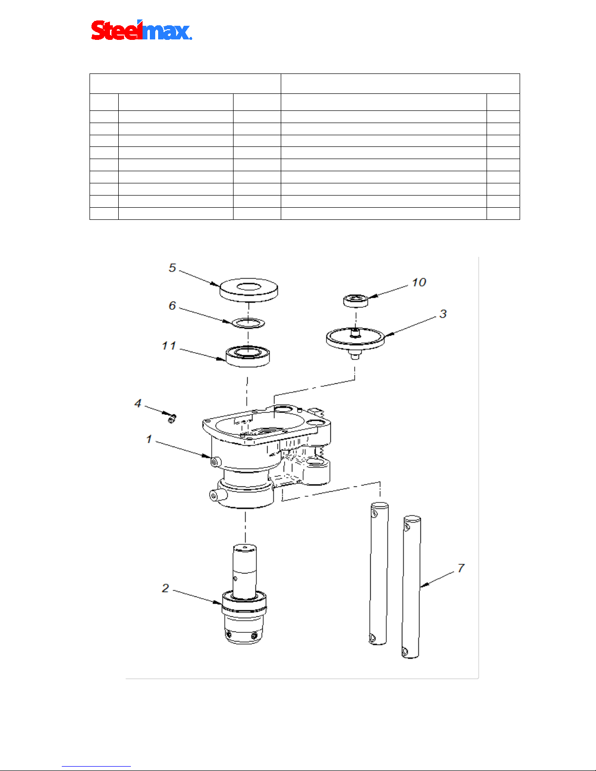
RDK-0440-02-00-00-1 GEARBOX ASSEMBLY
ITEM PART NUMBER VERSION DESCRIPTION QTY
2.1
KRP-0440-02-01-00-1
1551
GEARCASE ASSY
1
2.2
WRZ-0272-02-02-00-0
MOTOR SPINDLE ASSEMBLY
1
2.3
WLK-0271-02-03-00-1
PINION SHAFT ASSEMBLY
1
2.4
KNC-0234-00-10-00-0
COOLANT COUPLING AMT2-H-19
1
2.5
KOL-0271-02-05-00-1
GEAR - 52
1
2.6
PRS-0271-02-06-00-0
DISTANCE RING
1
2.7
PRT-0440-02-02-00-1
GUIDE
2
2.10
LOZ-000072
BEARING BALL 629 SHIELDED
1
2.11
LOZ-000047
BEARING BALL 6005 2RS
1

D1
- 19 -
D1 9/2011 Operators Manual for Drilling Machine
KRP-0440-02-01-00-1 GEARCASE ASSY
ITEM PART NUMBER VERSION DESCRIPTION QTY
2.1.1
KRP-0440-02-01-01-2
1550
GEARCASE
1
2.1.2
LST-0271-02-01-02-1
GEAR RACK
1
2.1.3
TLJ-000031
SELF-LUBRICATING SLEEVE 18x20x20
4
2.1.5
LOZ-000053
BEARING 608 2Z
1
2.1.6
PRS-000070
SEAL 25x37x7
2
2.1.7
KLK-000044
DOWEL, PIN 5 x 10 MM
2
2.1.8
KLK-000048
DOWEL, PIN 5 x 18
1
2.1.9 SRB-000111 HEX. SOCKET BOLT M6X18 1

D1
- 20 -
D1 9/2011 Operators Manual for Drilling Machine
WRZ-0272-02-02-00-0 MOTOR SPINDLE ASSEMBLY.
ITEM PART NUMBER VERSION DESCRIPTION QTY
2.2.1
KRP-0272-02-02-01-0
MOTOR SPINDLE
1
2.2.2
WYP-0139-00-02-00-1
PLUNGER
1
2.2.3
SPR-0271-02-02-03-0
SPRING
1
2.2.4 USZ-0279-02-01-06-0 SEAL 1
2.2.5
PRS-000009
INTERNAL RETAINING RING 19W
1
2.2.6
WKR-000059
HEX. SET SCREW M8 x 10
2
2.2.7
LOZ-000047
BEARING BALL 6005 2RS
1
Other manuals for SM-D1
2
Table of contents
Other SteelMax Drill manuals

SteelMax
SteelMax D300XT User manual

SteelMax
SteelMax SM-D1 User manual

SteelMax
SteelMax D1PRO User manual

SteelMax
SteelMax D4X User manual

SteelMax
SteelMax D3X RS User manual

SteelMax
SteelMax D250X User manual

SteelMax
SteelMax D1 AUTO User manual

SteelMax
SteelMax D1 Pro-X User manual

SteelMax
SteelMax D1 AUTO User manual

SteelMax
SteelMax SM-D2 User manual


