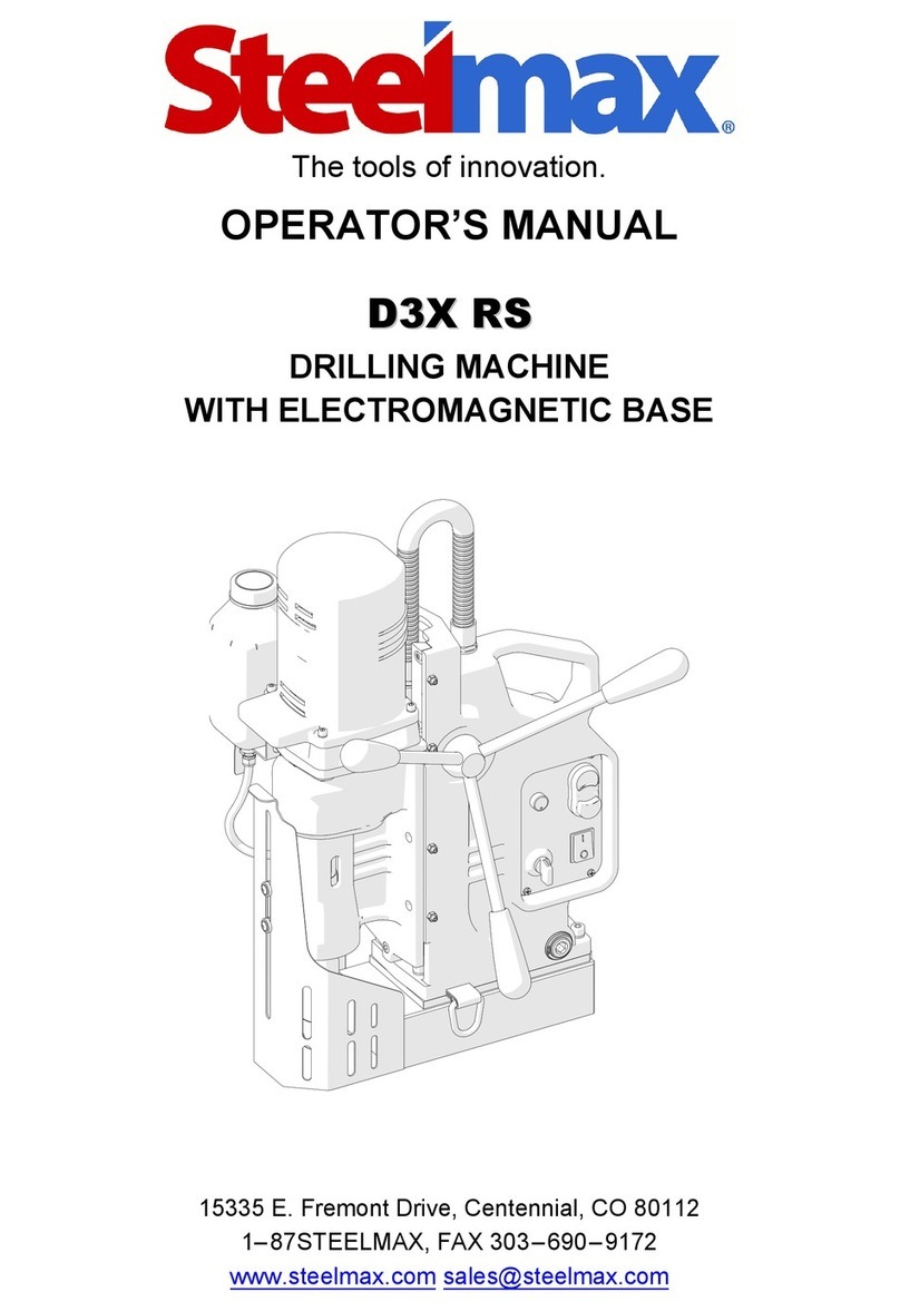
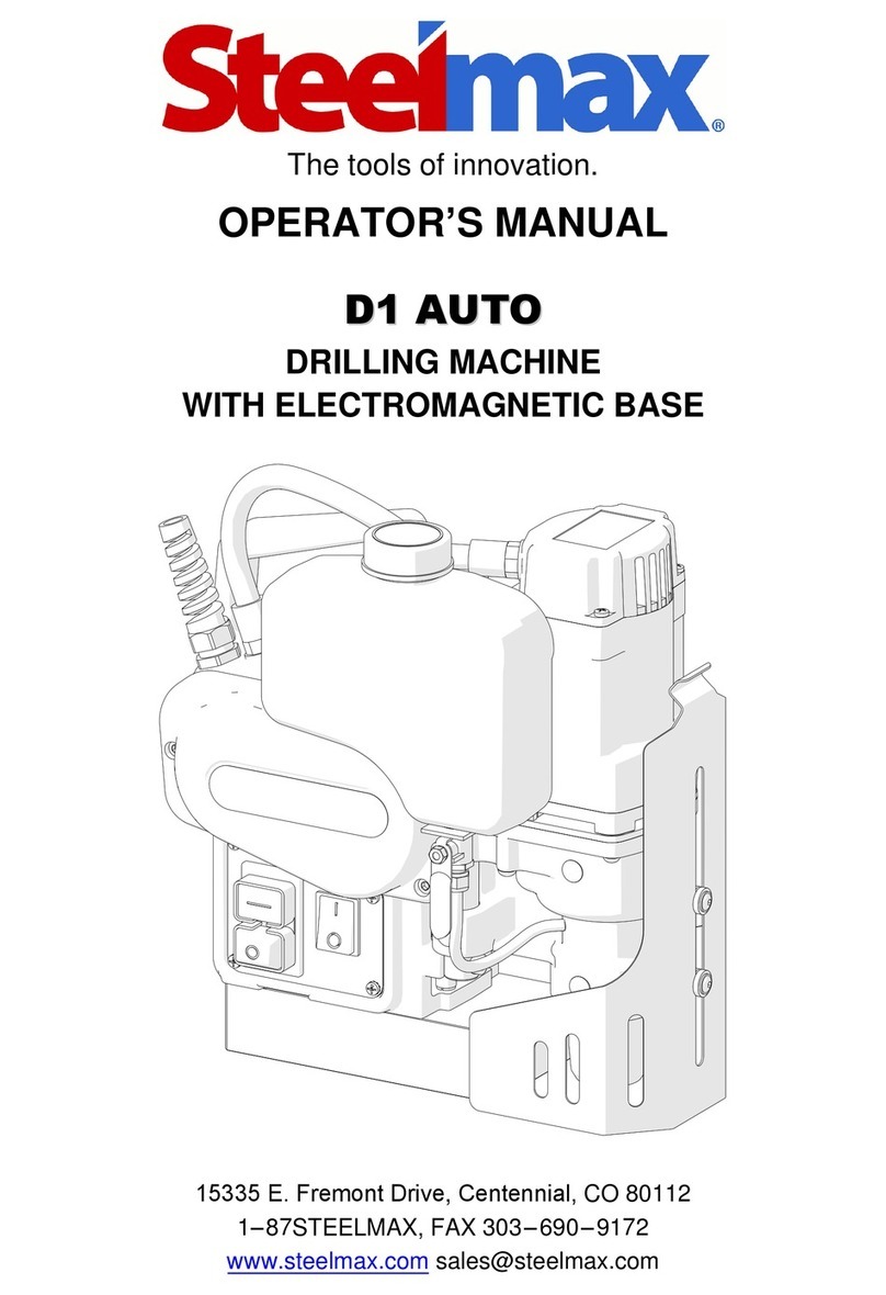
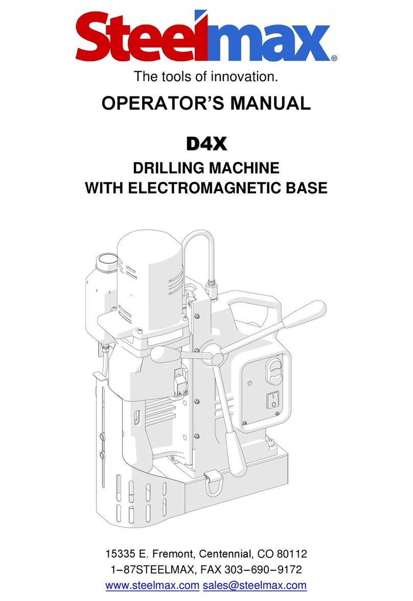
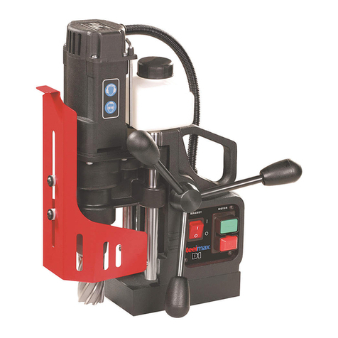
SteelMax SM-D1 User manual

The tools of innovation.
112 Inverness Circle East Suite F Englewood, CO 80112
1–87STEELMAX, FAX 303–690–9172
www.steelmax.com sales@steelmax.com
OPERATOR’S MANUAL
S
SM
M-
-D
D1
1
L
LO
OW
W
P
PR
RO
OF
FI
IL
LE
E
DRILLING MACHINE
WITH ELECTROMAGNETIC BASE

Contents
1. GENERAL INFORMATION............................................................................................... 3
1.1. Application................................................................................................................. 3
1.2. Technical data............................................................................................................ 3
1.3. Equipment included ................................................................................................... 4
1.4. Dimensions................................................................................................................ 5
1.5. Design ....................................................................................................................... 5
2. SAFETY PRECAUTIONS.................................................................................................. 6
3. STARTUP AND OPERATION........................................................................................... 8
3.1. Installing and removing the handle............................................................................. 8
3.2. Installing, removing, and operating the annular cutter................................................ 9
3.3. Preparing..................................................................................................................11
3.4. Drilling.......................................................................................................................13
3.5. Replacing the motor brushes ....................................................................................14
4. ACCESSORIES ...............................................................................................................15
4.1. Coolant bottle with nozzle.........................................................................................15
4.2. HSS quill assembly...................................................................................................15
5. WIRING DIAGRAM..........................................................................................................17
6. EXPLODED DRAWINGS AND PARTS LIST....................................................................18
7. DECLARATION OF CONFORMITY.................................................................................24
8. QUALITY CERTIFICATE..................................................................................................25
9. WARRANTY CARD..........................................................................................................26

SM-D1-LP
SM-D1-LP Operator’s Manual
3
1. GENERAL INFORMATION
1.1. Application
The SM-D1-LP is adrilling machine with electromagnetic base, designed to drill holes
with diameters of up to 36 mm (1-7/16’’) either to adepth of up to 20 mm (13/16’’) by
using HSS annular cutters or to adepth of up to 30 mm (1-3/16’’) by using TCT annular
cutters. When using twist drill bits with a19 mm (3/4’’) Weldon shank you can drill holes
with diameters of up to 12 mm (1/2’’) to a depth of up to 20 mm (13/16’’).
The electromagnetic base allows the drilling machine to be fixed to ferromagnetic
surfaces with a force that ensures operator safety and proper machine operation.
A safety strap protects the machine from falling in case of a power loss.
With an optional HSS quill assembly you can drill holes to adepth of up to 25 mm
(1’’) by using HSS cutters or twist drill bits with a 19 mm Weldon shank.
1.2. Technical data
Voltage
1~ 110–120 V, 50–60 Hz
1~ 220–240 V, 50–60 Hz
Total power
1000 W
Motor power
920 W
Tool holder
19 mm (3/4’’) Weldon
Maximum drilling diameter with annular cutter
36 mm (1-7/16’’)
Maximum drilling diameter with twist drill bit
12 mm (1/2’’)
Maximum drilling depth with HSS cutter or drill bit
20 mm (13/16’’)*
Maximum drilling depth with TCT cutter
30 mm (1-3/16’’)
Electromagnetic base holding force
(surface with the thickness of 25 mm and roughness Ra= 1.25)
8 900 N (1950 lbs)
Electromagnetic base dimensions
90 mm × 180 mm × 38.5 mm
3-9/16’’ × 7-1/16’’ × 1-1/2’’
Stroke
39 mm (1-1/2’’)
Rotational speed without load
550 rpm (for 115 V)
580 rpm (for 230 V)
Rotational speed under load
350 rpm (for 115 V)
370 rpm (for 230 V)
Minimum workpiece thickness
6 mm (1/4’’)
Protection class
I
Noise level
More than 85 dB
Required ambient temperature
0–40°C (32–104°F)
Weight
9.5 kg (21 lbs)
* Up to 25 mm (1’’) when used with an optional HSS quill assembly (ZSP-0521-04-00-00-0).

SM-D1-LP
SM-D1-LP Operator’s Manual
4
1.3. Equipment included
1
Drilling machine
1 unit
2
Plastic box
1 unit
3
Handle
1 unit
4
Handle adapter
1 unit
5
Pilot pin 7.98x85 for TCT cutters
1 unit
6
Pilot pin 6.34x74 for HSS cutters
1 unit
7
Safety strap
1 unit
8
4 mm hex wrench
1 unit
–
Operator’s Manual
1 unit
1
2
3
4
5
6
7
8

SM-D1-LP
SM-D1-LP Operator’s Manual
5
1.4. Dimensions
1.5. Design
176 mm (6-15/16’’)
147 mm (5-13/16’’)
380 mm (14-15/16’’)
MOTOR
stop button
Electromagnetic base
(MAGNET) switch
MOTOR
start button
Carrying handle
Electromagnetic base
Chip guard
Opening for safety strap
Control panel
TCT quill assembly including spindle with arbor

SM-D1-LP
SM-D1-LP Operator’s Manual
6
2. SAFETY PRECAUTIONS
1. Before starting, read this Operator’s Manual and complete proper occupational
safety and health training.
2. Use the machine only in applications specified in this Operator’s Manual.
3. The machine must be complete and all parts must be genuine and fully functional.
4. The specifications of the power source must conform to those specified on the
rating plate.
5. Connect the machine to a properly grounded power source. The power source must
be protected with a 16 A fuse for 230 V or a 32 A fuse for 115 V. When used on
building sites, supply the machine through an isolation transformer with class II
protection only.
6. Never carry the machine by the power cord and never pull the cord because this
may damage it and result in electric shock.
7. Transport and position the machine by using the carrying handle and only when
the MAGNET switch is set to ‘O’.
8. Untrained bystanders must not be present near the machine.
9. Before starting, ensure the correct condition of the machine, power source, power
cord, plug, control panel components, and tools.
10. Keep the machine dry, and do not expose it to rain, snow, or frost.
11. Never stay below the machine placed at heights.
12. Keep the work area well lit, clean, and free of obstacles.
13. Install the tools securely by tightening the set screws. Remove adjusting keys and
wrenches from the work area before connecting the machine to the power source.
14. Never use tools that are dull or damaged.
15. Do not make holes whose diameter or depth differ from those specified in the
technical data.
16. Install and remove tools by using protective gloves and only when the machine is
unplugged from the power source.
17. Never use annular cutters without a pilot pin except when drilling incomplete
through holes.
18. Never use near flammable liquids or gases, or in explosive environments.
19. Never use the machine on surfaces that are rusty, covered with a thick paint layer,
uneven, or not rigid.

SM-D1-LP
SM-D1-LP Operator’s Manual
7
20. Use the safety strap in all work positions by attaching the machine to a fixed
structure through the opening in the machine body. Never insert the strap into the
buckle from the front.
21. Before every use, inspect the machine to ensure it is not damaged. Check
whether any part is cracked or improperly fitted. Make sure to maintain proper
conditions that may affect the operation of the machine.
22. Always use eye and hearing protection and protective clothing during work.
Do not wear loose clothing.
23. The entire bottom of the electromagnetic base must be in full contact with the
workpiece. Before every positioning, wipe the workpiece with coarse-grained
sandpaper.
24. Do not touch moving parts or chips formed during milling. Prevent objects from
being caught in moving parts.
25. After every use, remove metal chips and excess coolant from the machine.
Do not remove chips with bare hands.
26. Cover steel parts with a thin anti-corrosion coating to protect the machine from
rust when not in use for any extended period.
27. Maintain the machine and install/remove parts and tools only when the machine
is unplugged from the power source.
28. Repair only in a service center appointed by the seller.
29. If the machine falls from any height, is wet, or has any other damage that could
affect the technical state of the machine, stop the work and promptly send the
machine to the service center for inspection and repair.
30. Never leave the machine unattended during work.
31. Remove from the worksite and store in a secure and dry place when not in use,
previously removing the tool from the holder.

SM-D1-LP
SM-D1-LP Operator’s Manual
8
3. STARTUP AND OPERATION
3.1. Installing and removing the handle
Install the handle by using the adapter as shown in Fig. 1. The handle can be installed
from the opposite side of the machine to allow working in places hard to reach or
using the machine by a left-handed person.
To remove the handle, pull it out.
Fig. 1. Installing the handle

SM-D1-LP
SM-D1-LP Operator’s Manual
9
3.2. Installing, removing, and operating the annular cutter
Unplug the machine from the power source, raise the chip guard, and then rotate the
handle to the left (1, Fig. 2) to access the set screws (2). Next, wear protective gloves,
insert the required pilot pin into the annular cutter (3), and then use a clean and dry
cloth to wipe the arbor and cutter. Next, place the cutter into the arbor (4) so that the
flats (5)are aligned with the set screws (2), and then use the 4 mm hex wrench to
tighten both set screws.
To remove the cutter, loosen the screws (2) with the 4 mm hex wrench.
Fig. 2. Installing the annular cutter
3
4
2
5
1

SM-D1-LP
SM-D1-LP Operator’s Manual
10
Fig. 3shows how annular cutters work. As the cutter penetrates the workpiece, the pilot
pin recesses into the arbor and tightens the spring. As a result, after the cutter goes
through the entire thickness, the slug core is expelled from the cutter.
Fig. 3. Annular cutters work
Annular cutters are designed to make only through holes shown in Fig. 4. When
drilling incomplete through holes the pilot pin must not be used.
Fig. 4. Types of holes to make with annular cutter
Slug core
Spring
Pilot pin
Annular cutter
Arbor
Incomplete through holes
Complete through holes

SM-D1-LP
SM-D1-LP Operator’s Manual
11
3.3. Preparing
Before starting, clean steel parts, including the arbor, from anti-corrosion coating
used to preserve the machine for storage and transport.
Install the handle as described before.
Based on the hole size desired, select the proper annular cutter or drill bit with a
19 mm Weldon shank. Next, use a clean and dry cloth to wipe the arbor and cutter
(drill bit), and then install the cutter (drill bit) into the arbor as described before.
Position the machine on a flat ferromagnetic surface with a thickness of at least
6 mm (1/4’’). The workpiece must be clean, without rust or paint that decrease the
holding force. The force value depends also on the type, thickness, flatness, and
roughness of the surface, fluctuations of the supply voltage, and the wear of the
electromagnetic base bottom. Some types of steel are non-ferromagnetic (do not
conduct magnetic flux) and the machine is not capable to clamp onto them.
Connect the machine to the power source, and set the MAGNET switch to ‘I’ to
turn on the clamping of the electromagnetic base.
Use the safety strap to prevent the machine from falling and avoid possible injury
to the operator if the machine loses magnetic clamping in case of a power loss. To
protect the machine, insert the strap through the opening in the machine body and
attach the machine to a fixed structure. The strap must be tight, not twisted (except
standard twist for horizontal drilling from Fig. 5c), and must be replaced every single
time the machine hangs on the strap as a result of coming loose from steel. Never
insert the strap into the buckle from the front (Fig. 5d).

SM-D1-LP
SM-D1-LP Operator’s Manual
12
Fig. 5. Protecting the machine from falling by using the safety strap
Rotate the handle to the left to place the pilot pin (drill bit) above the workpiece.
Fill the coolant bottle (not included) with a cutting fluid. Do not use pure water as
the cutting fluid. However, using emulsions formed from mixing water and drilling oil
is satisfactory.
When drilling in vertical positions (Fig. 5a), apply the coolant manually into the
drilling area. When drilling in inverted or horizontal positions (Fig. 5b, 5c) use coolants
under pressure or in the form of spray or paste.
a)
b)
Vertical drilling
Inverted drilling
c)
Horizontal drilling
Maximum possible
twist of the strap
d)
INCORRECT
CORRECT
✓

SM-D1-LP
SM-D1-LP Operator’s Manual
13
3.4. Drilling
Start the motor with the green MOTOR button, and slowly rotate the handle to the left
to lower the tool to the workpiece, and start drilling.
When using annular cutter, drill holes in one pass.
When using drill bits, drill holes with diameters of 8–12 mm (5/16’’ –1/2’’) in two
passes.Drillafirst hole by usingadrill bit with the 70% diameterof the hole size desired,
and then drill again by using a bit with the diameter equal to the hole size desired.
After the hole is made, retract the tool from the workpiece and press the red
MOTOR button to stop the motor. Before moving the machine to another drilling spot,
set the MAGNET switch to ‘O’ to turn off the electromagnetic base.
After the work is finished, unplug the machine from the power source, clean
chips and excess coolant from the machine and tool, and then remove the machine
from the worksite.
Before inserting the machine into the box, remove the handle, and then wear
gloves to remove the tool from the holder.
When the annular cutter goes through the workpiece, the
slug core is expelled from the cutter with a significant force.

SM-D1-LP
SM-D1-LP Operator’s Manual
14
3.5. Replacing the motor brushes
Check the condition of the carbon brushes every 100work hours. To do this, unplug the
machine from the power source, and unscrew the cover (1, Fig. 6). Next, unscrew the
pressing plate (2), and then remove the brush holder (3) and the brush (4). If the length
of the brush is less than 5 mm (3/16’’), replace both brushes with new ones.
To install brushes, proceed in reverse order. After the replacement, run the motor
without load for 20 minutes.
Fig. 6. Replacing the brushes
1
2
3
4

SM-D1-LP
SM-D1-LP Operator’s Manual
15
4. ACCESSORIES
4.1. Coolant bottle with nozzle
Capacity of 250 ml (8 oz).
4.2. HSS quill assembly
Allows you to drill holes to adepth of up to 25 mm (1’’) by using HSS annular cutters or
twist drill bits with a 19 mm (3/4’’) Weldon shank.
Part number:
PJM-000003
Part number:
ZSP-0521-04-00-00-0

SM-D1-LP
SM-D1-LP Operator’s Manual
16
To install the assembly, unplug the machine from the power source, raise the cover,
and then rotate the handle to the left (1,Fig. 7) to lower the standard TCT quill
assembly as much as possible. Next, remove the handle, use pliers to remove the
retaining rings (2), and then push out the shaft (3)by 16mm (10/16’’),which will expel
the TCT quill assembly (4). Insert the HSS quill assembly (5), push in the shaft (6), and
then place the retaining rings back in place (7).
Fig. 7. Installing the HSS quill assembly
1
7
2
3
4
5
6
2
7

SM-D1-LP
SM-D1-LP Operator’s Manual
17
5. WIRING DIAGRAM

SM-D1-LP
SM-D1-LP Operator’s Manual
18
6. EXPLODED DRAWINGS AND PARTS LIST
1
6
5
4
3
2
ITEM
PART NUMBER
DESCRIPTION
Q-TY
1
SKR-000012
PLASTIC BOX
1
2
PLT-0521-11-00-00-0
PILOT PIN 7.98x85
1
3
KLC-000007
4 MM HEX WRENCH
1
4
PRD-000002
TORQUE STICK
1
5
KLC-000048
RATCHET WRENCH 3-8
1
6
PLT-0378-15-00-00-0
PILOT PIN 6.34x74
1

SM-D1-LP
SM-D1-LP Operator’s Manual
19
52 53
54
55
49
38
34
4
25 26
42
45
18 19
40
39
51
57
59
50
17
48
37
44
41
56
46
36
16
35
20 21
33
47
22
32
30
31
43
58
23
15
14
29
13
28
27
3
24
9
8
7
12 11
10
3
6
5
2
1

SM-D1-LP
SM-D1-LP Operator’s Manual
20
ITEM
PART NUMBER
DESCRIPTION
Q-TY
1
WKR-000098
HEX SOCKET BUTTON HEAD SCREW M5x16
6
2
PKR-0521-02-00-00-1
GEARBOX COVER
1
3
KLK-000044
DOWEL PIN 5n6x10
3
4
KOL-0521-08-00-00-0
GEAR z63 ASSY
1
5
PRS-000223
EXTERNAL RETAINING RING 25z TYPE A
1
6
LOZ-000169
BALL BEARING 25x42x9
1
7
KOL-0521-08-01-00-0
GEAR z63
1
8
LOZ-000100
BALL BEARING 30x42x7
1
9
PRS-000021
EXTERNAL RETAINING RING 30z TYPE A
1
10
SPR-000063
DISC SPRING fi27.99xfi21.74x0.3
1
11
WLK-0521-07-00-00-0
PINION SHAFT z16 z32 ASSY
1
12
LOZ-000038
BALL BEARING 12x28x8
2
13
PDK-000221
WASHER 20x28x0.1
2
14
PDK-0521-13-00-00-0
SETTING WASHER
1
15
SLN-0521-03-00-00-1
MOTOR ASSY –120V
1
15
SLN-0521-03-00-00-3
MOTOR ASSY –230V
1
16
NSD-000009
HANDLE COVER
1
17
UCW-0521-12-00-00-0
HANDLE
1
18
WKR-000101
HEX SOCKET BUTTON HEAD SCREW M6x16
2
19
PDK-000021
ROUND WASHER 6.4
4
20
PRS-000019
EXTERNAL RETAINING RING 28z
2
21
PRS-000259
SEAL 20x28x4
1
22
TLJ-000010
SELF-LUBRICATING SLEEVE 28.05x32x1
2
23
KRP-0521-01-01-00-1
BODY
1
24
WLK-0521-10-00-00-0
FEED SHAFT z20
1
25
WKR-000302
SELF-TAPPING SCREW 5x30
4
26
WKR-000395
HEX SOCKET ROUND HEAD SCREW WITH FLANGE M5x20
2
27
PDK-000151
NYLON WASHER 8.1x14x3
4
28
OSL-0521-09-01-00-0
CHIP GUARD
1
29
SPR-000030
SPRING 1x10x17.5
2
30
ZSP-0521-30-00-00-0
QUILL ASSY TCT
1
31
PRS-000011
EXTERNAL RETAINING RING 20z
1
32
TLJ-0521-30-01-00-0
QUILL CARRIER TCT
1
33
LOZ-000045
BALL BEARING 20x42x12
1
34
PRS-000026
INTERNAL RETAINING RING 42w
1
35
WRZ-0378-03-02-00-0
SPINDLE
1
36
WKR-000063
HEX SOCKET SET SCREW WITH FLAT POINT M8x8
2
37
SPR-0378-03-04-00-0
SPRING
1
38
WYP-0378-03-05-00-0
PLUNGER
1
39
PDK-0139-00-04-00-0
WASHER 18.8x10x1
1
40
PRS-000009
INTERNAL RETAINING RING 19w
1
41
PDS-0521-14-00-00-0
ELECTROMAGNETIC BASE ASSY
1
42
SRB-000117
HEX SOCKET HEAD CAP SCREW M6x25
4
43
WLK-0521-06-00-00-0
PINION SHAFT z11 z26 ASSY
1
44
STR-0521-05-00-00-0
ELECTRONIC CONTROLLER ASSY –120V
1
44
STR-0521-05-00-01-0
ELECTRONIC CONTROLLER ASSY –230V (CEE)
1
44
STR-0521-05-00-02-0
ELECTRONIC CONTROLLER ASSY –230V (AU)
1
44
STR-0521-05-00-03-0
ELECTRONIC CONTROLLER ASSY –230V (INDIA)
1
45
SZN-0075-00-51-00-5
POWER CORD 120V 3x2.08 WITH STRAIN RELIEF ASSY (US)
1
45
SZN-0212-10-02-00-2
POWER CORD 230V 3x1.5 WITH STRAIN RELIEF ASSY (CEE)
1
45
SZN-0212-10-02-00-1
POWER CORD 230V 3x1 WITH STRAIN RELIEF ASSY (AU)
1
Other manuals for SM-D1
2
This manual suits for next models
1
Table of contents
Other SteelMax Drill manuals

SteelMax
SteelMax D2X User manual

SteelMax
SteelMax SM-D2 User manual
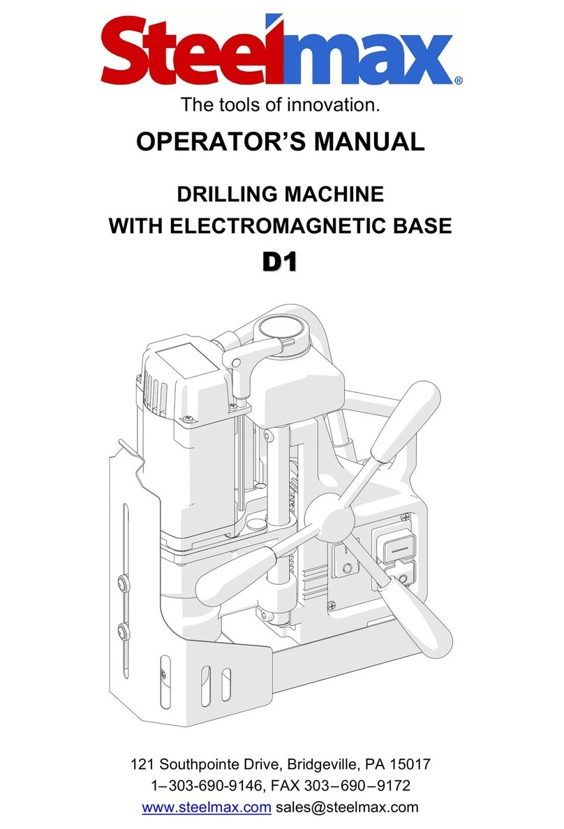
SteelMax
SteelMax D1 AUTO User manual
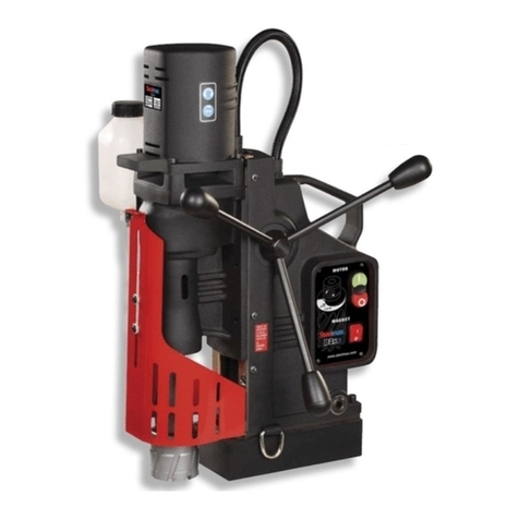
SteelMax
SteelMax D3X R User manual

SteelMax
SteelMax D2X User manual
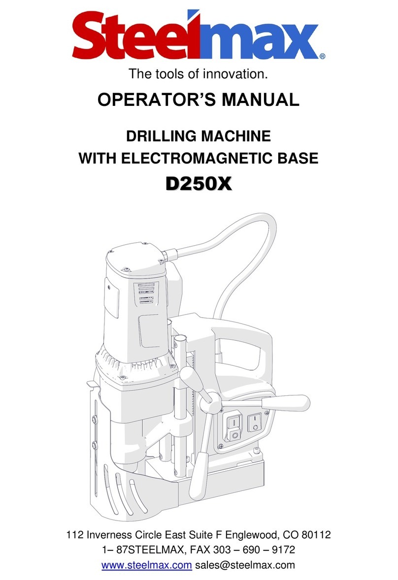
SteelMax
SteelMax D250X User manual

SteelMax
SteelMax D200XT User manual

SteelMax
SteelMax D300XT User manual
SteelMax
SteelMax SM-D1 User manual

SteelMax
SteelMax D1 AUTO User manual
Popular Drill manuals by other brands

Parkside
Parkside 73384 Original operating instructions

Ryobi
Ryobi R18DD3-2415BS Original instructions

BorMann
BorMann BCD2510 manual

Mafell
Mafell A12 Translation of the original operating instructions

Stanley
Stanley STDC1800 manual

Drill Master
Drill Master DRILL MASTER 96526 Set up and operating instructions
