SteelMax D3X RS User manual

The tools of innovation.
15335 E. Fremont Drive, Centennial, CO80112
1–87STEELMAX, FAX 303–690–9172
www.steelmax.com [email protected]
OPERATOR’S MANUAL
D
D3
3X
X
R
RS
S
DRILLING MACHINE
WITH ELECTROMAGNETIC BASE

Contents
1. GENERAL INFORMATION ............................................................................................... 3
1.1. Application ................................................................................................................. 3
1.2. Technical data............................................................................................................ 3
1.3. Design ....................................................................................................................... 5
1.4. Equipment included ................................................................................................... 5
2. SAFETY PRECAUTIONS.................................................................................................. 6
3. STARTUP AND OPERATION ........................................................................................... 8
3.1. Installing and removing the arbor, MT3 twist drill bit, or tap chuck.............................. 8
3.2. Installing, removing, and operating the annular cutter ...............................................10
3.3. Installing and removing the screw tap .......................................................................12
3.4. Installing and removing the cooling system ...............................................................13
3.5. Control system of the electromagnetic base holding force ........................................14
3.6. Preparing ..................................................................................................................14
3.7. Positioning the machine precisely .............................................................................16
3.8. Drilling.......................................................................................................................17
3.9. Tapping.....................................................................................................................18
3.10. Adjusting the gib clearance .....................................................................................19
3.11. Replacing the motor brushes...................................................................................21
4. ACCESSORIES ...............................................................................................................22
4.1. Pressure cooling system ...........................................................................................22
4.2. Arbor MT3 x 32 mm Weldon .....................................................................................22
4.3. Quick change arbor MT3 x 19 mm Weldon ...............................................................23
4.4. Pipe attachment DMP 501 ........................................................................................23
5. WIRING DIAGRAM ..........................................................................................................24
6. D3X RS EXPLODED DRAWINGS AND PARTS LIST......................................................25
7. DECLARATION OF CONFORMITY .................................................................................31
8. QUALITY CERTIFICATE..................................................................................................32
9. WARRANTY CARD..........................................................................................................33

D3X RS
D3X RS Operator’s Manual
3
1. GENERAL INFORMATION
1.1. Application
The D3X RS is a drilling machine with electromagnetic base, designed to drill holes
either with diameters of 12–75 mm (0.47–2.95’’) to a depth up to 76 mm (3’’) using
annular cutters or with diameters of 8–32 mm (0.31–1.26’’) to a depth up to 76 mm
(3’’) using twist drill bits. In addition, it is capable to change the rotation direction to
allow tapping by using a tap chuck with axial compensation.
The electromagnetic base allows the drilling machine to be fixed to ferromagnetic
surfaces with a force that ensures operator safety and proper machine operation.
A safety chain protects the machine from dropping in case of a power loss.
The D3X RS has a swivel base and thus is capable to be rotated in a range of
±15°andto be moved out up to 15 mm (0.6’’) without moving the electromagnetic base.
Accessories allow, for instance, quick changing of tools or drilling in pipes.
1.2. Technical data
Voltage
1~ 110–120 V, 50–60 Hz
1~ 220–240 V, 50–60 Hz
Total power
1800 W
Motor power
1650 W
Spindle shank
MT3
Tool holder
19 mm Weldon (3/4’’)
Drilling diameter with annular cutter
12–75 mm (0.47–2.95’’)*
Drilling diameter with twist drill bit
8–32 mm (0.31–1.26’’)
Maximum drilling depth
76 mm (3’’)
Maximum tap size
M24 (G3/4’’)
Electromagnetic base holding force
(surface with the thickness of 22 mm and roughness R
a
= 1.25)
19 500 N
Electromagnetic base dimensions
110 mm × 220 mm × 56 mm
4.3’’ × 8.7’’ × 2.2’’
Stroke
225 mm (8.9’’)
Rotational speed under load
80–160 rpm (gear I)
210–420 rpm (gear II)
Minimum workpiece thickness
10 mm (0.39’’)
Protection class
I
Noise level
More than 85 dB
Required ambient temperature
0–40°C (32–104°F)
Weight
27 kg (60 lbs)
*If more than 60 mm (2.3’’), MT3 arbor with 32 mm Weldon tool holder required (UCW-0191-00-00-00-0).

D3X RS
D3X RS Operator’s Manual
4
567 mm (22.3’’)
412 mm (16.2’’)
312 mm (12.3’’)
D3X RS
D3X RS Operator’s Manual
5
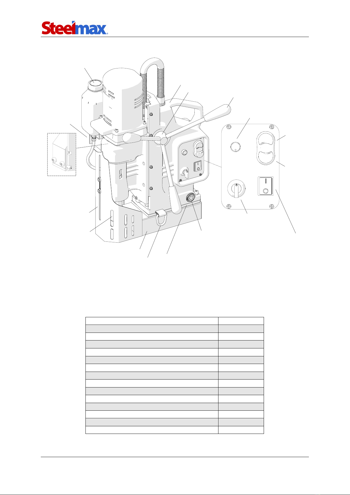
1.3. Design
Fig. 1. View of the D3X RS
1.4. Equipment included
The drilling machine is supplied including the following elements.
Drilling machine
1 unit
Metal box
1 unit
Spoke handle
3 units
MT3 arbor with 19 mm (3/4’’) Weldon tool holder
1 unit
Cooling system
1 unit
1.5 m (5 ft) safety chain
1 unit
MT3 drift
1 unit
2.5 mm hex wrench
1 unit
4 mm hex wrench
1 unit
5 mm hex wrench with handle
1 unit
6 mm hex wrench
1 unit
10 mm hex wrench
1 unit
8 mm combination wrench
1 unit
Tool can
1 unit
Operator’s Manual
1 unit
Cooling system bottle
Lug for safety chain
Electromagnetic base
Chip guard
Spoke handle
Carrying handle
Gear switch
(I / II)
Arbor
Motor
START
button
Motor
STOP
button
Swivel base
Rotation direction switch
(Left / O / Right)
Electromagnetic base
ON/OFF switch
Speed adjustment knob
Feed shaft
Eccentric shaft to lock
the swivel base
Bottle valve
lever

D3X RS
D3X RS Operator’s Manual
6
2. SAFETY PRECAUTIONS
1. Before beginning, read this Operator’s Manual and complete proper occupational
safety and health training.
2. Use the machine only in applications specified in this Operator’s Manual.
3. The machine must be complete and all parts must be genuine and fully operational.
4. The specifications of the power source must conform to those specified on the
rating plate.
5. Connect the machine to a properly grounded power source. The power source must
be protected with a 16 A fuse for 230 V or a 32 A fuse for 115 V. When used on
building sites, supply the machine through an isolation transformer with class II
protection only.
6. Never carry the machine by the power cord and never pull the cord because this
may damage it and result in electric shock.
7. Transport and position the machine using the carrying handle and only when the
magnet switch is set to the position ‘O’.
8. Untrained bystanders must not be present near the machine.
9. Before beginning, make sure that the correct is the condition of the machine, power
source, power cord, plug, control panel components, and tools.
10. Keep the machine dry. Exposure to rain, snow, or frost is prohibited.
11. Never stay below the machine placed at heights.
12. Keep the work area well lit, clean, and free of obstacles.
13. Install the tools securely. Tighten the annular cutter using set screws. Hammer in
the drill bit into the spindle using a mallet. Remove adjusting keys and wrenches
from the work area before connecting the machine to the power source.
14. Never use cutters that are dull or damaged.
15. Do not make holes whose diameter or depth differ from those specified in the
technical data.
16. Install and remove tools using protective gloves and only when the power cord is
unplugged from the power source.
17. Never use annular cutters without a pilot pin except when drilling incomplete
through holes. Never use arbors without a spring.
18. Never use near flammable liquids or gases, or in explosive environments.
19. Using the machine on surfaces that are rusty, covered with a thick paint layer,
uneven, or not rigid is prohibited.

D3X RS
D3X RS Operator’s Manual
7
20. Do not start operation if the gib clearance is excessive.
21. Use the safety chain in all operating positions. Attach the machine to a fixed
structure by fastening the chain to the lugs or the carrying handle. The chain
must not be loose. Wrap the chain around the workpiece if possible.
22. Before every use, inspect the machine to ensure it is not damaged. Check
whether any part is cracked or improperly fitted. Make sure to maintain proper
conditions that may affect the operation of the machine.
23. Always use eye and hearing protection and protective clothing during operation.
Do not wear loose clothing.
24. Drilling in plates with a thickness less than 10 mm (0.4’’) is not recommended
because the holding force depends on material thickness and is significantly
lower for thin plates.
25. The entire bottom of the electromagnetic base must be in full contact with the
workpiece. Before every positioning, wipe the workpiece with coarse-grained
sandpaper.
26. Do not touch moving parts or chips formed during milling. Prevent objects from
being caught in moving parts.
27. After every use, remove metal chips and excess coolant from the machine. Do
not remove chips with bare hands.
28. Cover steel parts with a thin anti-corrosion coating to protect the machine from
rust when not in use for any extended period.
29. Maintain the machine and install/remove parts and tools only when the machine
is unplugged from the power source.
30. Repair only in a service center appointed by the seller.
31. If the machine falls from any height, is wet, or has any other damage that could
affect the technical state of the machine, stop the operation and immediately
send the machine to the service center for inspection and repair.
32. Never leave the machine unattended during operation.
33. Remove from the worksite and store in a secure and dry location when not in
use, previously removing the tool from the holder.

D3X RS
D3X RS Operator’s Manual
8
3. STARTUP AND OPERATION
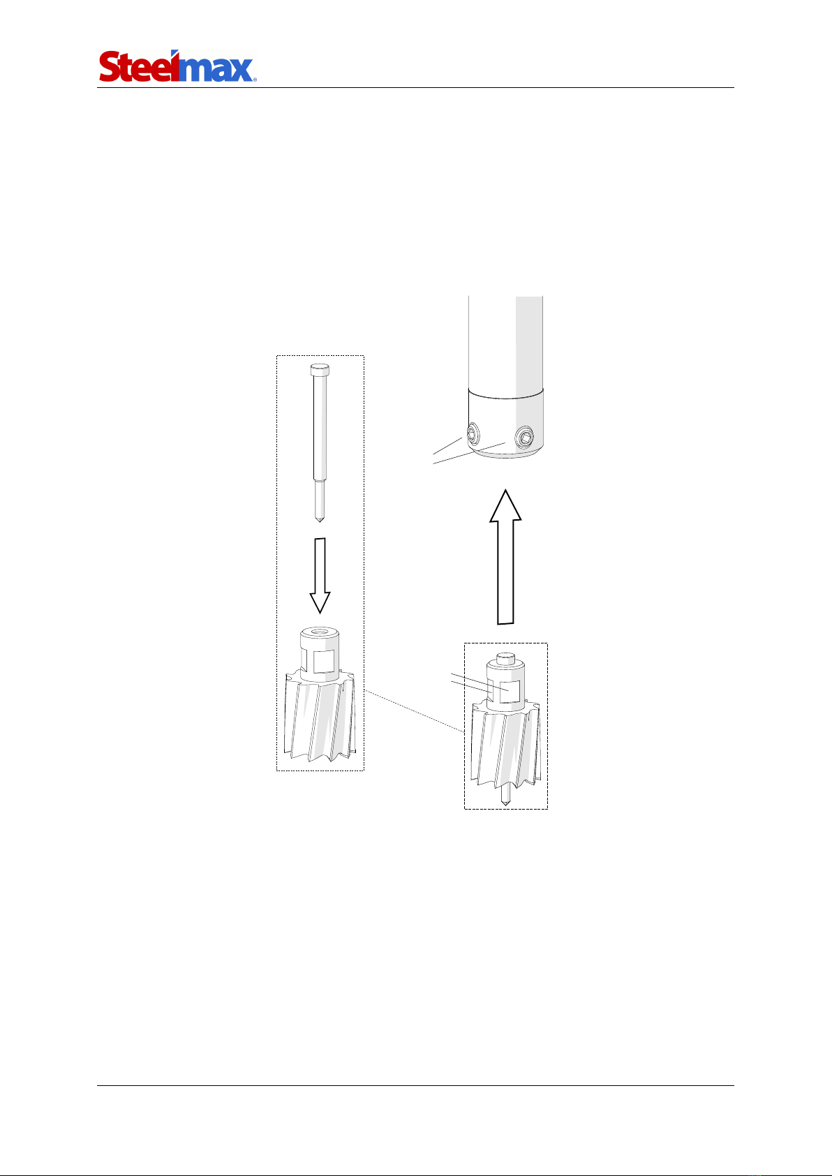
3.1. Installing and removing the arbor, MT3 twist drill bit, or
tap chuck
Unplug the machine from the power source, raise the chip guard as high as possible
(1, Fig. 2), and then rotate the spoke handles to the right (2) to raise the motor. Use a
clean and dry cloth to wipe the spindle and arbor (drill bit, tap chuck). Next, wear
protective gloves and insert the arbor (drill bit, tap chuck) into the spindle (3), and
then rotate the arbor (drill bit, tap chuck) to the right (4) until it slips into place. Finally,
firmly tap the arbor (drill bit, tap chuck) into place using a mallet (5).
Fig. 2. Installing the arbor, drill bit, or tap chuck
2
1
3
5
4

D3X RS
D3X RS Operator’s Manual
9
To remove the arbor (drill bit, tap chuck), raise the motor, and then rotate the
spindle (1, Fig. 3) in such a way to align the openings in the spindle and gearbox (2).
Next, insert the MT3 drift (3) into the opening above the arbor (drill bit, tap chuck),
hold the carrying handle with one hand, and then tap the drift using a mallet (4).
Fig. 3. Removing the arbor, drill bit, or tap chuck
1
2
3
4
D3X RS
D3X RS Operator’s Manual
10
3.2. Installing, removing, and operating the annular cutter
Install the arbor as described before, wear protective gloves, and then insert the
proper pilot pin into the annular cutter (1, Fig. 4). Use a clean and dry cloth to wipe
the cutter. Next, place the cutter into the arbor (2) in such a way to align the flats 3
with the set screws 4, and then use the 5 mm hex wrench to tighten both set screws.
To remove the cutter, loosen the screws 4using the 5 mm hex wrench.
Fig. 4. Installing the annular cutter
1
2
4
3
D3X RS
D3X RS Operator’s Manual
11
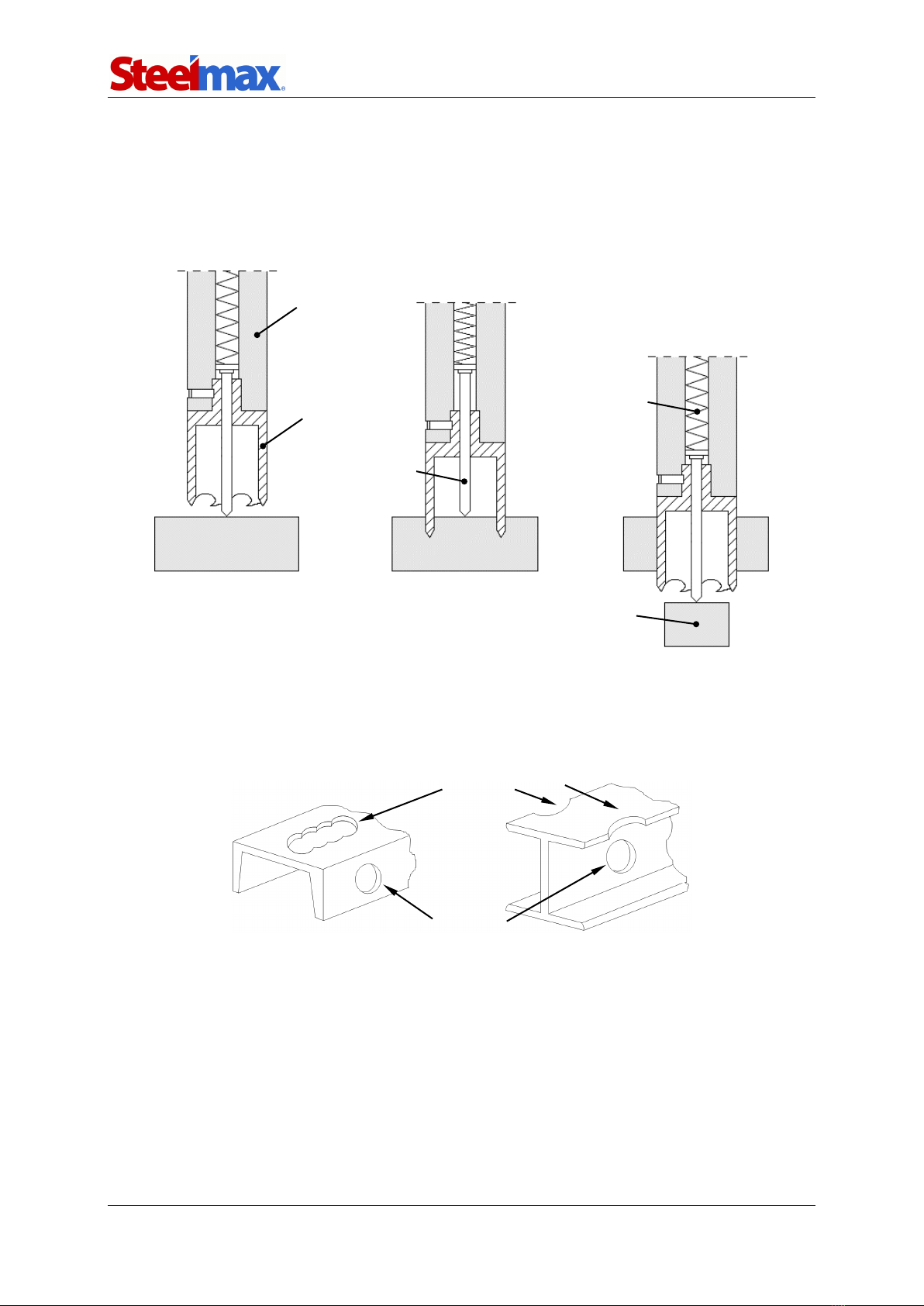
Fig. 5shows how annular cutters operate. As the cutter penetrates the workpiece,
the pilot pin recesses into the arbor and tightens the spring. As a result, after the cutter
goes through the entire thickness, the slug core is expelled from the cutter. When
pressed, the pilot pin also allows application of coolant to the inner surface of the
annular cutter.
Fig. 5. Annular cutters operation
Annular cutters are designed to make only through holes shown in Fig. 6. When
drilling incomplete through holes the pilot pin must not be used.
Fig. 6. Types of holes to make with annular cutters
Incomplete through holes
Complete through holes
Slug core
Spring
Pilot pin
Annular cutter
Arbor
D3X RS
D3X RS Operator’s Manual
12
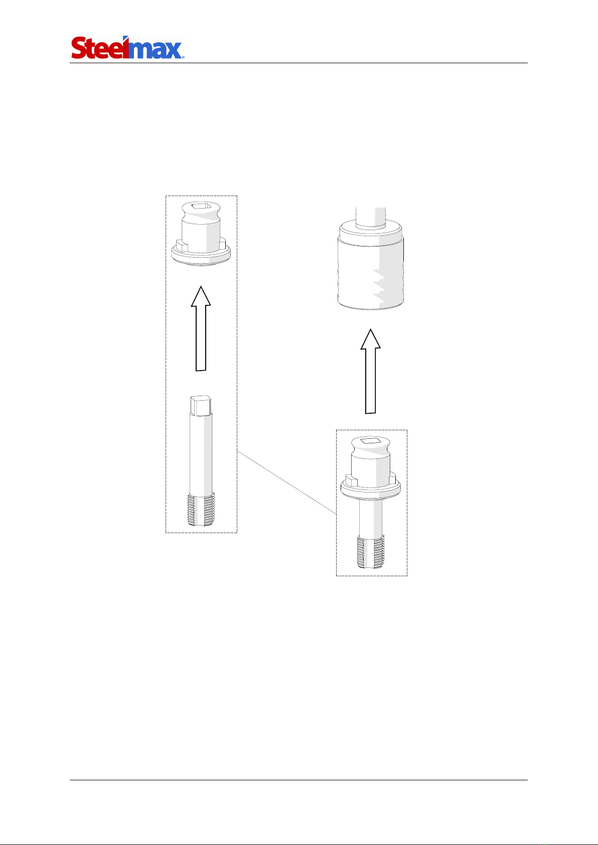
3.3. Installing and removing the screw tap
Install the tap chuck with axial compensation as described before. Next, insert the
entering tap (tap no. 1) into the proper adapter (1, Fig. 7), and then install the adapter
into the tap chuck (2). Install screw taps with a MT3 shank through a MT sleeve.
To remove the screw tap, unlock it and remove from the adapter.
Fig. 7. Installing the screw tap
1
2

D3X RS
D3X RS Operator’s Manual
13
3.4. Installing and removing the cooling system
Hang the cooling system bottle on the screws (1, Fig. 8), and then attach the bottle
hose to the hose fitting (2).
To remove the bottle, proceed in reverse order.
Fig. 8. Installing the cooling system
1
2

D3X RS
D3X RS Operator’s Manual
14
3.5. Control system of the electromagnetic base holding force
The D3X RS drilling machine incorporates a holding force control system to monitor
the clamping of the electromagnetic base to the surface. The force value depends on
several factors, such as type, thickness, flatness, and roughness of the surface,
presence of paint, rust, or other contaminants, fluctuations of supply voltage, and the
wear of the electromagnetic base bottom.
If the holding force falls below a safe operating value, the control system will not
allow the machine to operate. Additionally, the system will prevent the startup of the
motor on asurface thinner than 5mm (0.2’’) because such thickness does not provide
sufficient holding force. In such a case, the holding force will be only about 25% of
the force attained on a standard 22-mm (0.87’’) flat plate.
If the motor does not continue operation after the green MOTOR button is pressed
and released, it means that the control circuit is operating properly and preventing
further drilling because the holding force is too low.
3.6. Preparing
Before beginning, clean steel parts, including the MT3 shank, from anti-corrosion
coating used to preserve the machine for storage and transport.
Screw the spoke handles into the feed shaft. The feed shaft can be installed at
the opposite side of the drilling machine to allow working in places hard to reach or
using the machine by a left-handed person.
Select the proper annular cutter, drill bit, or screw tap based on the hole size
desired. Next, use aclean anddry cloth to wipe the spindle, arbor (drill bit, tap chuck),
and cutter, and then install the arbor (and then the cutter), drill bit, or tap chuck (and
then the screw tap with adapter) as described before.
Position the machine on a flat ferromagnetic surface (some types of stainless and
acid-proof steel do not conduct magnetic flux) with a thickness of at least 10 mm (0.4’’).
The workpiece must be clean, without rust or paint that decrease the holding force of
the electromagnetic base.
Connect the drilling machine to the power source, and set the MAGNET switch to
the position ‘I’ to turn on the clamping of the electromagnetic base.
Use the safety chain to prevent the machine from dropping and avoid possible
injury to the operator if the machine loses magnetic clamping in case of a power loss.

D3X RS
D3X RS Operator’s Manual
15
To protect the machine, attach it to a fixed structure by fastening the chain to the lugs
or the carrying handle (Fig. 9). The chain must not be loose. Wrap the chain around
the workpiece if possible.
Fig. 9. Protecting the machine from dropping using the safety chain
Rotate the spoke handles to the left to place the tool above the workpiece.
When using the annular cutter and working in the positon from Fig. 9a, install the
cooling system as described before, and fill it with a cutting fluid. Do not use pure
water as the cutting fluid. However, using emulsions formed from mixing water and
drilling oil is satisfactory. To check the operation of the cooling system, slightly loosen
the bottle cap, open the valveusing the lever, and then rotate the spoke handles to
the left to initially apply pressure on the pilot pin. The fluid should fill the system and
begin flowing from the inside of the cutter.
Because the cooling system works by means of gravitation, use a cooling paste
when working in horizontal or inverted positions.
a)
b)
c)
Vertical drilling
Horizontal drilling
Horizontal drilling
(chain fastened to the
carrying handle)
d)
Inverted drilling

D3X RS
D3X RS Operator’s Manual
16
3.7. Positioning the machine precisely
To rotate or to move out the machine body when the electromagnetic base is clamped
to the workpiece, use the 10 mm hex wrench to unlock the eccentric shaft (1, Fig. 10),
set the body in desired position, and then lock the shaft (2).
Fig. 10. Positioning the D3X RS precisely
15°
15 mm
1
2
2
15°

D3X RS
D3X RS Operator’s Manual
17
3.8. Drilling
Use the gear switch to set the speed based on the following table.
Tool
Hole diameter
Rotational speed*
[rpm]
[mm]
[in.]
Annular cutter
12–34
0.47–1.34
210–420 (gear II)
35–75
1.38–2.95
80–160 (gear I)
Twist drill bit
8–17
0.31–0.67
210–420 (gear II)
18–32
0.71–1.26
80–160 (gear I)
* for sharp tool and mild steel with a shear strength R
m
< 500 N/mm2(70,000 psi),
such as for instance St0 (S185), St3S (S235JR), or St4W (S275JO)
Steel with a shear strength Rm= 500–700 N/mm2(70,000–100,000 psi), such as
for instance St5 (E295), 18G2A (S355N), or 45 (C45), requires lower rotational speed.
If the speed is selected too high or low for the shear strength and the type/diameter of
the tool, the tool will wear faster or be unable to drill the hole.
Set the rotation direction switch to the position ‘R’, and start the motor using the
green MOTOR button. Slowly rotate the spoke handles to the left to lower the tool to
the workpiece, and begin drilling. Next, use the speed adjustment knob to set a speed
suitable for given process conditions.
When using annular cutters, drill holes in one pass.
When using drill bits, drill holes with diameters of 18–32 mm (0.71–1.26’’) in two
passes. Drill a first hole using a drill bit with the 70% diameter of the hole size desired,
and then drill again using the bit with diameter equal to the hole size desired.
When drilling holes deeper than 50 mm (2’’), retract the tool above the workpiece
as often as possible to allow chips to be removed from the hole. If the grooves of the
tool are clogged, stop the motor and use a brush to clean them. After the drilling depth
exceeds 40 mm (1.6’’), apply the cutting fluid manually into the drilling area.
If the operation results in an overload, caused by insufficient cooling, using dull
tool, or too fast feed in relation to the tool diameter, the machine will automatically stop.
In such a case, to restart the machine, press the red MOTOR button, retract the tool
from the workpiece, and then press the green MOTOR button (the electromagnetic
base must remain powered).
When the annular cutter goes through the workpiece, the slug
core is expelled from the cutter with a significant force.

D3X RS
D3X RS Operator’s Manual
18
After the hole is made, retract the tool from the workpiece and press the red
MOTOR button to stop the motor. Before moving the machine to another drilling spot,
set the MAGNET switch to the position ‘O’ to turn off the electromagnetic base.
After the work is finished and the motor is stopped, switch to the opposite gear
(for instance from gear I to II), and then run the machine for awhile without load,
which will improve lubricity. Next, turn off the motor and the electromagnetic base,
unplug the machine from the power source, clean chips and excess coolant from the
machine and tool, and then remove the machine from the worksite.
Tighten the bottle cap, close the valve, and then press the pilot pin to expel the
coolant remaining within the cooling system. Before inserting the machine into the tool
box, remove the bottle, and then wear gloves to remove the tool from the holder.
3.9. Tapping
With the entering tap (tap no. 1) installed, use the gear switch to set the gear I, and
set the rotation direction switch to the position ‘R’.
Rotate the spoke handles to the left to place the tap above a hole with diameter
appropriate for the tap used. If the diameter of the hole is too small, tapping may be
impossible due to excessive milling resistance and insufficient motor power.
Spread tap oil on the cutting part of the screw tap to prevent seizure and extend
durability. Next, press the green MOTOR button to start the motor, and then slowly
rotate the spoke handles to the left to lower the tap to the workpiece, and begin
tapping. After tapping with the entering tap (tap no. 1) is finished, press the red
MOTOR button to stop the motor, and set the rotation direction switch to the position
‘L’. Next, press and hold the green MOTOR button to retract the tap from the hole,
and then release the button.
After the motor is stopped, replace the entering tap (tap no. 1) with the bottoming
tap (no. 3), and repeat tapping by proceeding as described before.
After the work is finished and the motor is stopped, set the gear II, and then run
the machine for a while without load, which will improve lubricity.
Next, turn off the motor and the electromagnetic base, and then unplug the
machine from the power source.

D3X RS
D3X RS Operator’s Manual
19
3.10. Adjusting the gib clearance
Every 50 operation hours, or more often, check the gib clearance because it greatly
influences the quality of drilled holes. The clearance is appropriate if the motor slides
smoothly and not drops under its own weight.
To remove the excessive clearance, use the 8 mm combination wrench to loosen
the nuts (1, Fig. 11), and then use the 2.5 mm hex wrench to loosen the set screws (2).
Next, rotate the spoke handles to set the motor on such a level to access the gib
screws through the holes, use the 4 mm hex wrench to loosen these screws (3), and
then tighten (4) with a force enough to prevent the gib from being pushed out by the
springs located inside.
Use the 2.5 hex wrench to tighten the set screws (5) to such an extent that the
motor moves smoothly through the entire stroke and not drops under its own weight.
Next, use the 4 mm hex wrench to tighten the gib screws: central screw (6), adjacent
screws, and then top and bottom screws. Finally, use the 8 mm combination wrench to
tighten the nuts (7), while countering the set screws using the 2.5 mm hex wrench (8).

D3X RS
D3X RS Operator’s Manual
20
Fig. 11. Adjusting the gib clearance
1
2
3
4
5
6
7
8
Table of contents
Other SteelMax Drill manuals

SteelMax
SteelMax D2X User manual

SteelMax
SteelMax D3X R User manual

SteelMax
SteelMax D2X User manual

SteelMax
SteelMax D4X User manual

SteelMax
SteelMax D1 AUTO User manual

SteelMax
SteelMax D200XT User manual

SteelMax
SteelMax D250X User manual

SteelMax
SteelMax D1PRO User manual

SteelMax
SteelMax D4X User manual

SteelMax
SteelMax D300XT User manual


