SteelMax D300XT User manual

The tools of innovation.
15335 E. Freemont Drive,Centennial, CO 80112
1– 87STEELMAX, FAX 303 – 690 – 9172
www.steelmax.com [email protected]
OPERATOR’S MANUAL
DRILLING MACHINE
WITH ELECTROMAGNETIC BASE
D
D3
30
00
0X
XT
T

Contents
1. GENERAL INFORMATION ............................................................................................... 3
1.1. Application ................................................................................................................. 3
1.2. Technical data............................................................................................................ 3
1.3. Equipment included ................................................................................................... 4
1.4. Dimensions ................................................................................................................ 5
1.5. Design ....................................................................................................................... 6
2. SAFETY PRECAUTIONS.................................................................................................. 7
3. STARTUP AND OPERATION ........................................................................................... 9
3.1. Installing the handles ................................................................................................. 9
3.2. Installing and removing the arbor, MT3 twist drill bit, or tap chuck.............................10
3.3. Installing and removing the annular cutter.................................................................12
3.4. Installing and removing the screw tap .......................................................................13
3.5. Installing and removing the cooling system ...............................................................14
3.6. Preparing ..................................................................................................................15
3.7. Drilling.......................................................................................................................17
3.8. Thread cutting...........................................................................................................19
3.9. Adjusting the gibs......................................................................................................20
3.10. Replacing the motor brushes...................................................................................21
4. ACCESSORIES ...............................................................................................................22
4.1. Pressure cooling system ...........................................................................................22
4.2. Arbor MT3 × 32 mm Weldon .....................................................................................22
4.3. Pipe attachment DMP 251 ........................................................................................23
4.4. MT3 tap chuck × 19 mm with adapter .......................................................................24
4.5. MT3 tap chuck × 31 mm with adapter .......................................................................25
5. DECLARATION OF CONFORMITY .................................................................................27
6. WARRANTY CARD..........................................................................................................37

D300XT
D300XT Operator’s Manual
3
1. GENERAL INFORMATION
1.1. Application
The D300XT is a drilling machine designed to drill holes with diameters of up to
70 mm (2-3/4″) by using annular cutters. The machine can also drill holes with diame-
ters of up to 25 mm (1″) by using twist drill bits.
The machine can change the direction of rotation. This allows thread cutting by
using a tap chuck.
The electromagnetic base clamps the machine to ferromagnetic surfaces. This
makes sure that the operator is safe and the machine works correctly. A safety strap
protects the machine from falling in case of a clamping loss.
Accessories allow you to drill in pipes and cut threads.
1.2. Technical data
Voltage
1~ 220–240 V, 50–60 Hz
1~ 110–120 V, 50–60 Hz
Power
1600 W
Spindle shank
MT3
Tool holder
19 mm (3/4″) Weldon
Drilling diameter with an annular cutter
70 mm (2-3/4″)*
Drilling diameter with a twist drill bit
25 mm (1″)
Maximum drilling depth with an annular cutter
75 mm (2-15/16″)
Maximum tap size
M20 (7/8″)
Clamping force
(surface with the thickness of 25 mm and roughness Ra= 1.25)
11,000 N
Electromagnetic base dimensions
92 mm × 180 mm × 54 mm
3.6″ × 7.1″ × 2.1″
Stroke
190 mm (7.5″)
Rotational speed under load
120–190 rpm (gear I)
290–450 rpm (gear II)
Minimum workpiece thickness
8 mm (0.3″)
Protection class
I
Noise level
More than 70 dB
Required ambient temperature
0–40°C (32–104°F)
Weight
18 kg (40 lbs)
* If more than 60 mm (2-3/8″), use an MT3 arbor with 32 mm Weldon tool holder (UCW-0563-22-00-00-0).
D300XT
D300XT Operator’s Manual
4
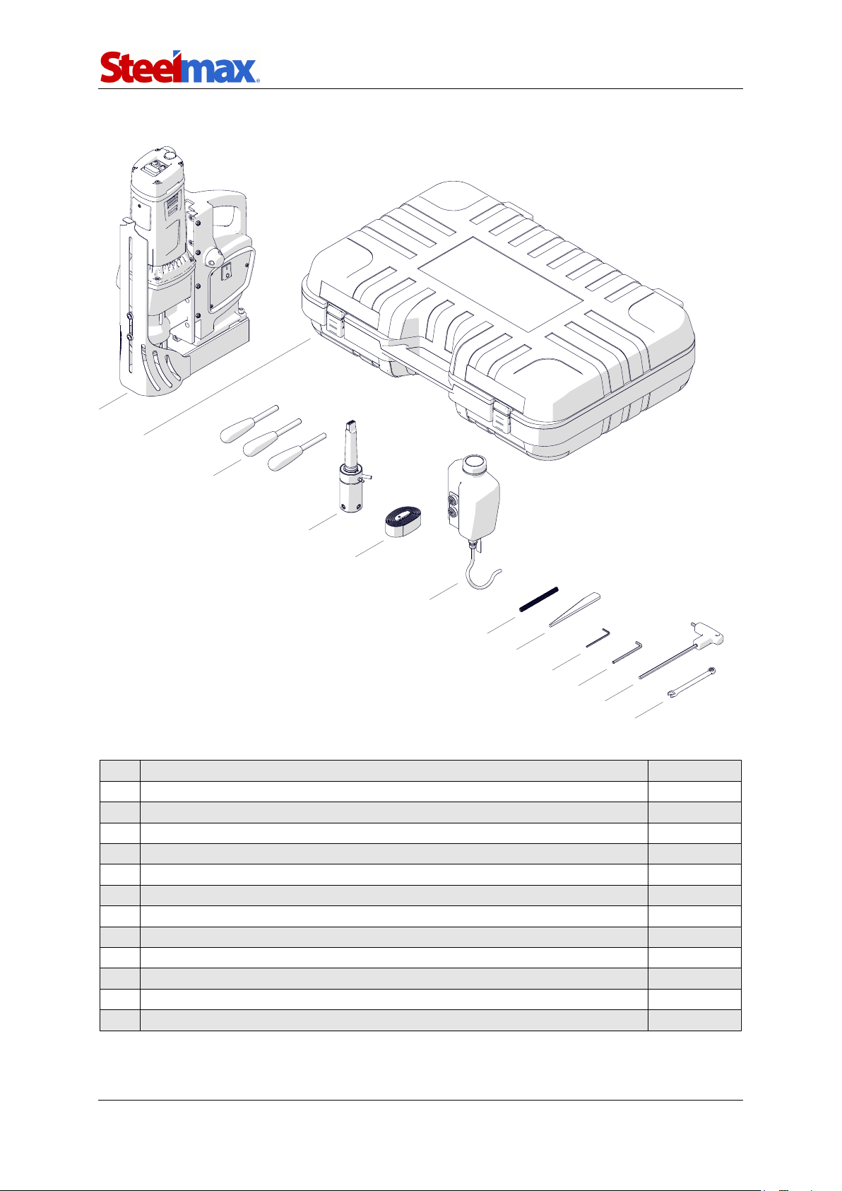
1.3. Equipment included
1
Drilling machine
1 unit
2
Plastic box
1 unit
3
Handle
3 units
4
MT3 arbor with 19 mm (3/4″) Weldon tool holder
1 unit
5
Safety strap
1 unit
6
Cooling system
1 unit
7
Protective spring for cooling hose
1 unit
8
MT3 drift
1 unit
9
2.5 mm hex wrench
1 unit
10
4 mm hex wrench
1 unit
11
5 mm hex wrench with a handle
1 unit
12
8 mm combination wrench
1 unit
–
Operator’s Manual
1 unit
7
8
9
10
11
12
6
5
4
3
1
2
D300XT
D300XT Operator’s Manual
5
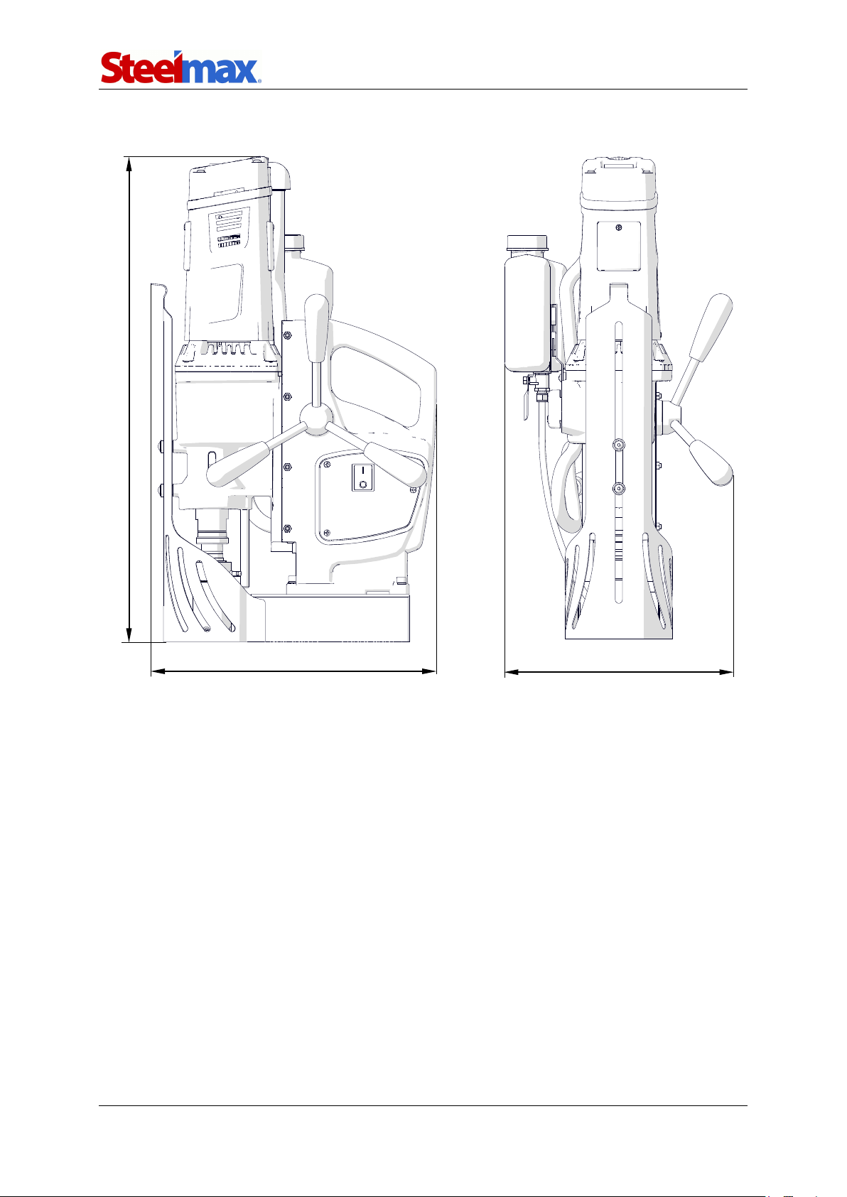
1.4. Dimensions
325 mm (12.8″)
265 mm (10.4″)
554 mm (21.8″)

D300XT
D300XT Operator’s Manual
6
1.5. Design
Gear switch
Chip guard
Speed knob
Bottle valve lever
Motor STOP
Motor START
(right rotation)
Motor START
(left rotation, only to retract the tap)
Carrying handle
Feed shaft
Electromagnetic base (MAGNET) switch
Electromagnetic base
Signal LED
Hole for a safety strap
Gib

D300XT
D300XT Operator’s Manual
7
2. SAFETY PRECAUTIONS
1. Before use, read this Operator’s Manual and complete a training in occupational
safety and health.
2. Use only in applications specified in this Operator’s Manual.
3. Make sure that the machine has all parts and they are genuine and not damaged.
4. Make sure that the specifications of the power source are the same as those
specified on the rating plate.
5. Connect the machine to a correctly grounded power source. Protect the power
source with a 16 A fuse for 230 V or a 32 A fuse for 115 V. If you are going to work
on building sites, supply the machine through an isolation transformer with class II
protection only.
6. Set the MAGNET switch to ‘O’ before you move the machine. Use carrying handle
to move the machine.
7. Do not carry the machine by the power cord and do not pull the cord. This can
cause damage and electric shock.
8. Keep untrained bystanders away from the machine.
9. Before each use, ensure the correct condition of the machine, power source,
power cord, plug, control panel, and tools.
10. Before each use, make sure that no part is cracked or loose. Make sure to main-
tain correct conditions that can have an effect on the operation of the machine.
11. Keep the machine dry. Do not expose the machine to rain, snow, or frost.
12. Do not stay below the machine that is put at heights.
13. Keep the work area well lit, clean, and free of obstacles.
14. Make sure that the tool is correctly attached. Remove wrenches from the work
area before you connect the machine to the power source.
15. Do not use tools that are dull or damaged.
16. Unplug the power cord before you install and remove tools. Use protective gloves
to install and remove tools.
17. Use annular cutters without the pilot pin only when you drill incomplete through
holes. Do not use arbors without a spring.
18. Do not make holes/threads whose diameter or depth differ from those specified
in the technical data.
19. Do not use near flammable materials or in explosive environments.

D300XT
D300XT Operator’s Manual
8
20. Do not use on surfaces that are rough, not flat, not rigid, or have rust, paint,
chips, or dirt.
21. Do not use if the gibs are adjusted incorrectly.
22. Do not use if there is no grease on the gibs.
23. Use the safety strap to attach the machine to a stable structure. Put the strap
through the hole in the machine body. In the horizontal position, attach the strap
to the carrying handle. Do not put the strap into the buckle from the front.
24. Use eye and ear protection and protective clothing. Do not use loose clothing.
25. We do not recommend work on workpieces thinner than 8 mm (0.3″). The clamp-
ing force depends on the workpiece thickness and is much lower for thin plates.
26. Each time before you put the machine on the workpiece, rub the workpiece with
coarse-grained sandpaper. Make sure that the bottom of the base is in full con-
tact with the workpiece.
27. Do not touch chips or moving parts. Do not let anything catch in moving parts.
28. After each use, remove chips and coolant from the machine and the tool. Do not
remove chips with bare hands.
29. Unplug the power cord before you do maintenance or install/remove parts.
30. Repair only in a service center appointed by the seller.
31. If the machine falls, is wet, or has any damage, stop the work and immediately
send the machine to the service center for check and repair.
32. Do not leave the machine when it operates.
33. If you are not going to use the machine, remove the tool from the holder. Then,
remove the machine from the work area and keep it in a safe and dry place.
34. If you are not going to use the machine for an extended period, put anti-corrosion
material on the steel parts.

D300XT
D300XT Operator’s Manual
9
3. STARTUP AND OPERATION
3.1. Installing the handles
Attach the handles to the feed shaft. You can install the shaft so that the handles are
on the opposite side of the machine. To do this, lift the motor to the maximum and
continue in the sequence that follows.
1
2 (20 mm, 0.8″)
3 (30 mm, 1.2″)
4
6 (30 mm, 1.2″)
5
7 (20 mm, 0.8″)
8

D300XT
D300XT Operator’s Manual
10
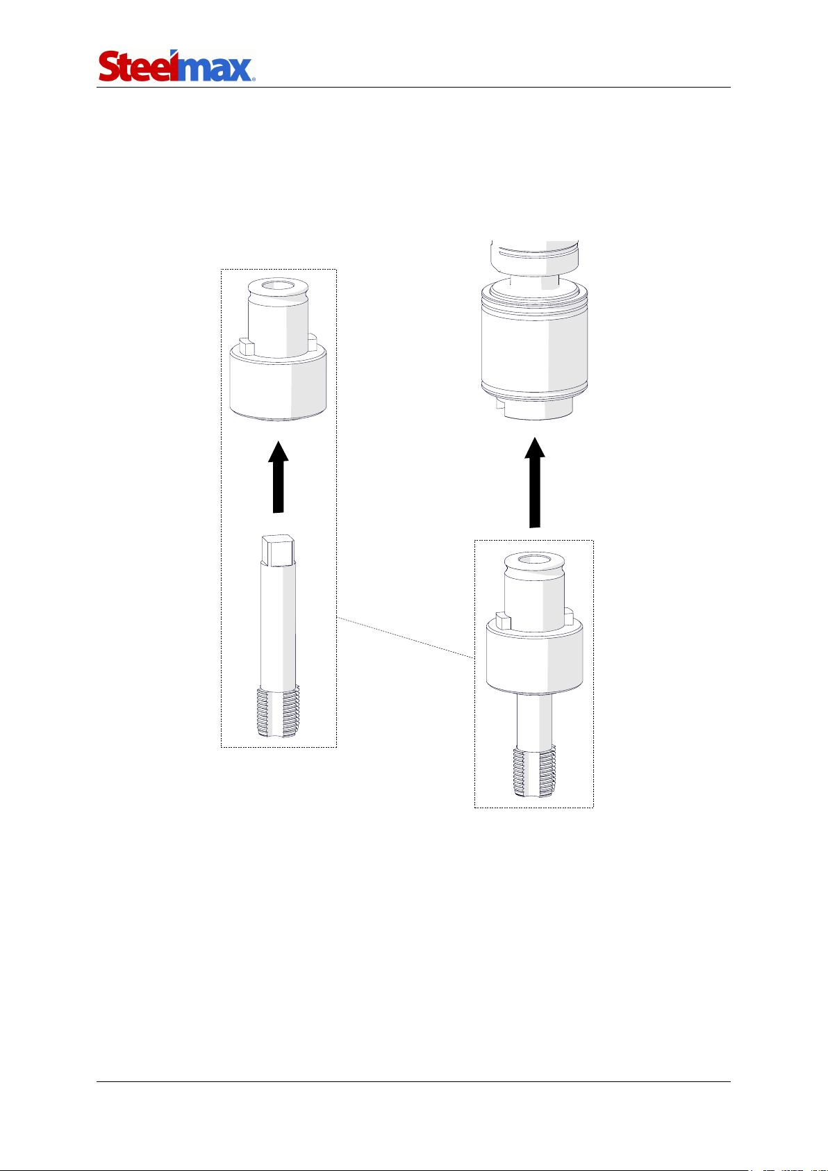
3.2. Installing and removing the arbor, MT3 twist drill bit, or
tap chuck
Unplug the power cord and lift the chip guard (1). Rotate the handles to the right (2)
to lift the motor. Use a dry cloth to clean the spindle and the arbor (drill bit, tap
chuck). Use gloves to put the arbor (drill bit, tap chuck) into the spindle (3). Make
sure that the stop rod is between the pin and the fitting (4). If the arbor (tap chuck)
has a nut (5), tighten the nut to the spindle.
1
2
3
5
4

D300XT
D300XT Operator’s Manual
11
To remove the arbor (drill bit, tap chuck), continue as follows. If the arbor (tap
chuck) has a nut (1), remove the nut. Next, lift the motor and rotate the spindle (2) to
align the holes in the spindle and gearbox (3). Put the drift into the hole (4). Next,
hold the carrying handle with one hand and hit the drift with a mallet (5).
2
3
4
5
1

D300XT
D300XT Operator’s Manual
12
3.3. Installing and removing the annular cutter
Install the arbor as described before. Use gloves to put the correct pilot pin into the
annular cutter (1). Use a dry cloth to clean the cutter. Put the cutter into the arbor (2)
to align the flat surfaces (3) with the screws (4). Use the 5 mm hex wrench to tighten
the screws.
To remove the cutter, loosen the screws (4) with the 5 mm hex wrench.
1
2
4
3
D300XT
D300XT Operator’s Manual
13
3.4. Installing and removing the screw tap
Install the tap chuck as described before. Next, put the screw tap into the correct
adapter (1). Install the adapter into the tap chuck (2).
To remove the screw tap, unlock it and remove from the adapter.
1
2
D300XT
D300XT Operator’s Manual
14
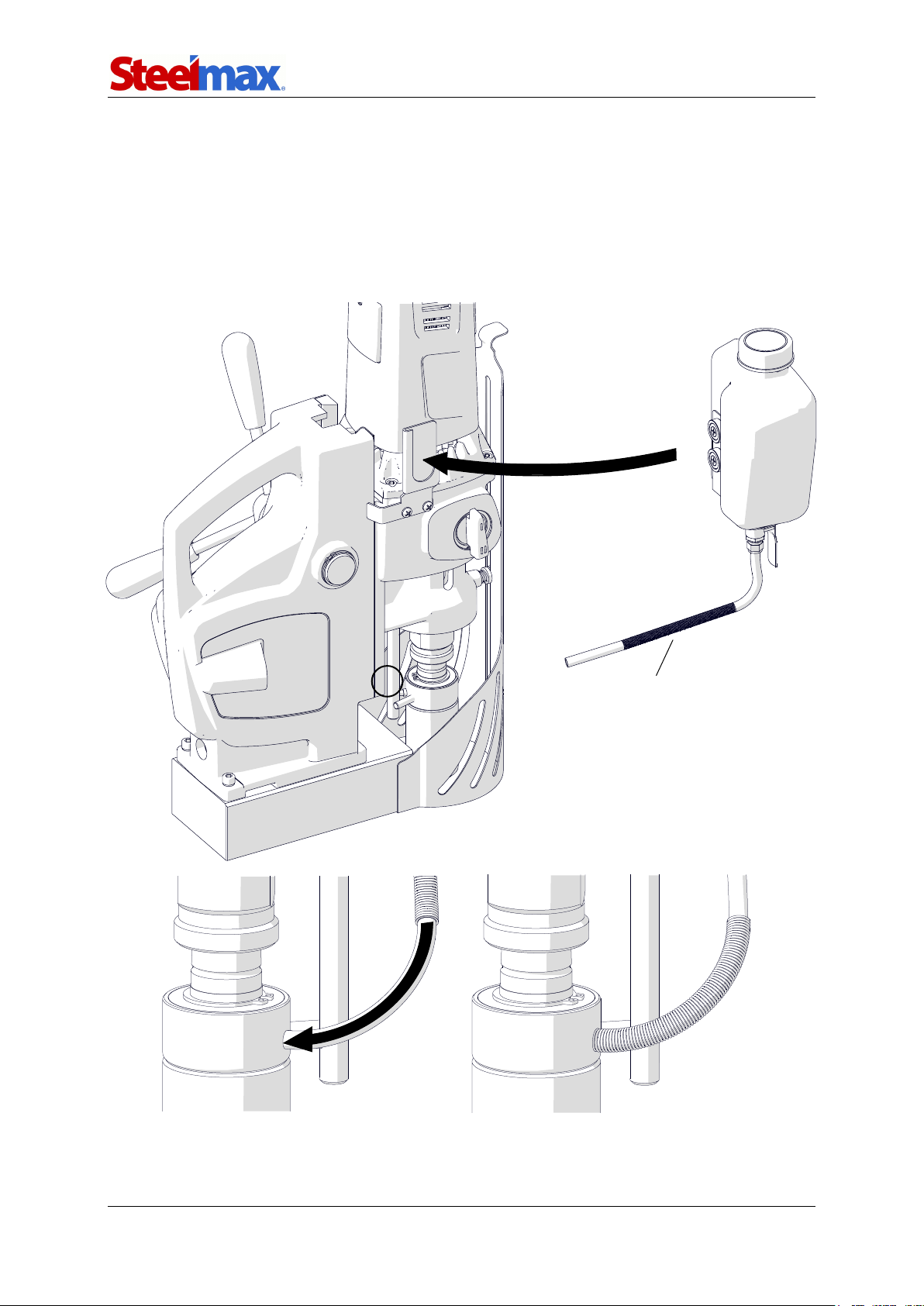
3.5. Installing and removing the cooling system
Attach the bottle to the bracket (1). Put the hose with the spring (2) between the stop
rod and the body (3). Then, attach the hose to the fitting and move the spring to the
arbor (4, 5).
To remove the bottle, continue in reverse sequence.
1
3
2
4
5

D300XT
D300XT Operator’s Manual
15
3.6. Preparing
Before use, clean steel parts, including the MT3 socket, from anti-corrosion material
used to preserve the machine for storage and transport.
Attach the handles to the feed shaft. You can install the shaft so that the handles
are on the opposite side of the machine.
Apply a thin layer of grease to the gibs.
Select the annular cutter, drill bit, or screw tap that matches the required hole
diameter. When you drill holes with diameters of 18–25 mm (0.7–1″) by using twist
drill bits, select two bits: with 70% and 100% of the required diameter.
Use a dry cloth to clean the spindle, arbor (drill bit, tap chuck), and cutter. Then,
as described before, install the arbor (and then the cutter), drill bit with the smaller
diameter, or tap chuck (and then the screw tap with adapter).
Put the machine on a flat ferromagnetic workpiece with the thickness of at least
8 mm (0.3″). Make sure that there is no rust, paint, chips, or dirt. They decrease the
clamping force. The force will be lower also if the surface is thin, rough, not flat, not
rigid, the voltage is lower than required, or the bottom of the base is worn.
Connect the machine to the power source. Set the MAGNET switch to ‘I’ to turn
on the clamping. Some types of steel (non-ferromagnetic) do not conduct magnetic
flux so the machine cannot clamp onto them.
Use the safety strap to prevent fall and injury if the machine loses the clamping.
Attach the machine to a stable structure by putting the strap through the hole in the
machine body. In the horizontal position, attach the strap to the carrying handle.
Make sure that the strap is tight and not twisted. If the machine comes loose from the
workpiece and hangs on the strap, replace the strap. Do not put the strap into the
buckle from the front.

D300XT
D300XT Operator’s Manual
16
Rotate the handles to the left to put the tool above the workpiece.
When you use an annular cutter, install the cooling system and fill it with coolant.
Do not use only water as the coolant. But you can mix water and drilling oil. Then,
make sure that the cooling system works correctly. To do this, lightly loosen the
bottle cap and use the lever to open the valve. Then, rotate the handles to the left to
apply a light pressure on the pilot pin. The coolant should fill the system and start
flowing from the cutter.
The cooling system works by gravity. Thus, in the horizontal position, rotate the
bottle. In the inverted position, use coolants under pressure or in the form of spray
or paste.
Vertical drilling
Inverted drilling
Horizontal drilling
INCORRECT
CORRECT
✓

D300XT
D300XT Operator’s Manual
17
3.7. Drilling
Use the gear switch to set the gear based on the table that follows.
Tool
Hole diameter
Rotational speed*
[rpm]
[mm]
[in]
HSS annular cutter
12–30
0.47–1.18
290–450 (gear II)
31–65
1.22–2.56
120–190 (gear I)
TCT annular cutter
12–34
0.47–1.34
290–450 (gear II)
35–70
1.38–2.76
120–190 (gear I)
Twist drill bit
<15
<0.59
290–450 (gear II)
15–25
0.59–0.98
120–190 (gear I)
* For a sharp tool and mild steel with a strength Rm< 500 N/mm2(70,000 psi), such as St0 (S185), St3S
(S235JR), or St4W (S275JO).
Steel with a strength Rm≥500 N/mm2(70,000 psi), such as St5 (E295), 18G2A
(S355N), or 45 (C45), requires lower speeds. If the speed is too high or too low for
the workpiece strength and the type/diameter of the tool, the tool will wear faster or
be unable to drill the hole.
Press to start the motor. Rotate the handles to the left to put the tool into the
workpiece. Use the speed knob to set a speed sufficient for the actual process condi-
tions. Set the speed knob near the maximum.
When the annular cutter goes through the workpiece, the slug core is
pushed out with a large force.
When you use an annular cutter, drill only through holes. For incomplete through
holes do not use the pilot pin.
Keep the machine in the same position until the hole is made.
Incomplete through holes
Complete through holes

D300XT
D300XT Operator’s Manual
18
When you use a drill bit, drill holes with diameters of 18–25 mm (0.71–0.98″) in
two steps. First, use the drill bit with the 70% diameter of the required diameter to drill
a hole. Then, keep the machine in the same position, and drill again with the drill bit
that matches the required diameter.
If you are going to drill holes deeper than 50 mm (2″), retract the tool above the
workpiece as often as possible. This allows chips to be removed from the hole. If the
grooves of the tool are clogged, turn off the motor and use a brush to clean them.
After you get to the depth of 40 mm (1.6″), retract the tool above the workpiece
as often as possible. Then, manually apply the coolant from the bottle into the
drilling area.
The table that follows shows the meaning of the LED colors.
Color
Meaning
Description
Green is on
Strong surface.
Ready to work.
Green flashes
Weak surface.
We do not recommend work.
White is on
Normal work.
–
Blue flashes
Near overload.
Do not increase the feed speed. This can cause
emergency stop.
Red is on
Overheat.
Immediately retract the tool from the workpiece!
Operate with no load for 2–4 minutes to let the
temperature of the motor decrease.
Blue is on
Emergency stop.
Overload.
Make sure that the tool is sharp. Make sure that
the motor speed and the feed are correct. Use
coolant. Retract the tool from the workpiece,
press STOP, and then start again.
Violet is on
Emergency stop.
Machine tilt/vibrations
or the surface not
stable.
Make sure that the surface is stable and its
thickness is at least 8 mm (0.3″). Press STOP
and then start again. If the motor does not
operate, contact the service center.
Red changes to
blue
Emergency stop.
Voltage drop.
Make sure that the power source is correct.
Press STOP and then start again.
Red changes to
green
Emergency stop.
Worn brushes.
Replace the brushes. Let the motor operate
with no load for 20 minutes. If the motor does
not operate, contact the service center.
The green color is indicative only. It does not make sure that the ma-
chine will always be in contact with the surface. Thus, in each posi-
tion protect the machine with the safety strap.
If an overload occurs, the machine stops. The overload can be caused by not
enough cooling, dull tool, too fast feed, or too slow speed. Then, to start the machine
again, retract the tool from the workpiece, press STOP and then .

D300XT
D300XT Operator’s Manual
19
After the hole is made, retract the tool from the workpiece, and press STOP
to turn off the motor. Before you move the machine, set the MAGNET switch to ‘O’ to
turn off the base.
After the work is finished and the motor turned off, set the gear switch to the
opposite position. Then, turn on the motor and let it operate for a while with no load
to improve lubrication. Next, turn off the motor and the base, and then unplug the
power cord. Clean the machine and the tool, and then remove the machine from the
work area.
Tighten the bottle cap, close the valve, and then press the pilot pin to remove the
coolant that remains in the cooling system. Before you put the machine into the box,
remove the bottle, and use gloves to remove the tool from the holder.
3.8. Thread cutting
Install the screw tap and use the gear switch to set the gear I.
Rotate the handles to the left to put the tap above the hole for the thread. If the
diameter of the hole is too small, cutting may not be possible because of too much
milling resistance.
Apply oil on the cutting part of the tap to prevent seizure and increase durability.
Press to start the motor. Set the speed knob near the minimum. Then, rotate
the handles to the left to put the tap into the hole. Use the handle to guide the tap
down until the thread is cut. After the cutting with the tap is finished, press STOP to
turn off the motor. Then, press and hold and use the handle to guide the tap up
to prevent damage to the thread.
After the work is finished and the motor turned off, set the gear switch to the
opposite position. Start the motor and let it operate for a while with no load to improve
lubrication. Next, turn off the motor and the base, and then unplug the power cord.

D300XT
D300XT Operator’s Manual
20
3.9. Adjusting the gibs
Every 50 work hours, make sure that the gibs are correctly adjusted. To do this,
move the motor up and down and make sure that it moves smoothly.
To adjust the gibs, apply a thin layer of grease on them. Then, use the 8 mm
combination wrench, the 2.5 mm hex wrench, and the 4 mm hex wrench to loosen
the nuts and screws (1). Put the motor so that the slider is in the center of the gibs
(2). Then, lightly tighten the screws (3) so that they touch the gib. Move the motor up
and down and adjust the screws (3) so that the travel is smooth. Next, tighten the
screws (4) and then tighten the nuts (5).
1
2
3
4
5
Table of contents
Other SteelMax Drill manuals

SteelMax
SteelMax SM-D1 User manual

SteelMax
SteelMax D200XT User manual

SteelMax
SteelMax D1 AUTO User manual

SteelMax
SteelMax D1 AUTO User manual

SteelMax
SteelMax D1PRO User manual

SteelMax
SteelMax D2X User manual

SteelMax
SteelMax D4X User manual

SteelMax
SteelMax D250X User manual

SteelMax
SteelMax D4X User manual

SteelMax
SteelMax D1PRO User manual


