SteelMax ABM-28 User manual

The tools of innovation.
15335 E. Fremont Drive, Centennial, CO 80112
1–87STEELMAX, FAX 303–690–9172
www.steelmax.com [email protected]
OPERATOR’S MANUAL
A
AB
BM
M-
-2
28
8
Auto Feed Beveling Machine
for Plate Edges

Contents
1. GENERAL INFORMATION............................................................................................... 3
1.1. Application................................................................................................................. 3
1.2. Technical data............................................................................................................ 3
1.3. Design ....................................................................................................................... 4
1.4. Equipment included ................................................................................................... 6
2. SAFETY PRECAUTIONS.................................................................................................. 7
3. STARTUP AND OPERATION........................................................................................... 9
3.1. Assembling................................................................................................................ 9
3.2. Setting the bevel parameters ....................................................................................11
3.3. Operating..................................................................................................................12
3.4. Replacing the cutting inserts.....................................................................................14
3.5. Replacing the milling head........................................................................................15
3.6. Using optional milling unit supports...........................................................................16
4. ACCESSORIES...............................................................................................................18
4.1. Support for beveling 36–70 mm plates at 0° to 60° ...................................................18
4.2. Support for beveling 36–70 mm plates at 0° to –60° .................................................18
4.3. 1.2 m (47’’) guide track..............................................................................................19
4.4. Support for J-beveling 20–70 mm plates...................................................................19
4.5. Clamp for 36–70 mm plates......................................................................................20
4.6. Track clamp for 36–70 mm plates.............................................................................20
4.7. Clad removal attachment..........................................................................................21
4.8. Clamp of clad removal attachment for 36–80 mm and 81–127 mm plates ................23
4.9. Track clamp of clad removal attachment for 36–80 mm and 81–127 mm plates .......23
5. WIRING DIAGRAM..........................................................................................................24
6. SPARE AND WEARING PARTS......................................................................................25
7. EXPLODED DRAWINGS AND PARTS LIST....................................................................26
8. DECLARATION OF CONFORMITY.................................................................................33
9. WARRANTY CARD..........................................................................................................34

ABM-28
ABM-28 Operator’s Manual
3
1. GENERAL INFORMATION
1.1. Application
The ABM-28 is abeveling machine designed to mill edges of plates with the thickness
of up to 35 mm (1.38’’). The beveling angle can be set in the entire range from 60°to
–60°, including facing at 0°. The feed is performed automatically after starting the
machine.
Accessories allow beveling of 36–70 mm (1.38–2.76’’) thick plates at the angle set
in the entire range from 0° to 60°(including facing) or from 0° to –60°. It is also
possible to establish J-bevels in 20–70 mm (0.79–2.76’’) thick plates and to remove
clad of up to 5 mm (0.2’’) depth from plates with a thickness of up to 127 mm (5’’).
1.2. Technical data
1211 mm
(47.7’ ’ )
619 mm (24.4’’)
532 mm (20.9’’)

ABM-28
ABM-28 Operator’s Manual
4
Voltage
1~ 220–240 V, 50–60 Hz
Power
1600 W
Rotational speed (without load)
2780 rpm
Protection level
IP 20
Protection class
I
Bevel angle (ß)
60 to –60° (Fig. 1)
Maximum bevel width (b)
35 mm (1.38’’, Fig. 1)
Feed speed
250–500 mm/min (10–20 in/min)
Minimum plate thickness
10 mm (0.39’’)
Minimum plate width*
110 mm (4.33’’)
Weight
78.5 kg (173 lbs)
* The plate and the guide must be well fixed, and the machine must be
balanced.
Fig. 1. Bevel dimensions; maximum bevel width depending on the angle
1.3. Design
The ABM-28 beveling machine consists of a milling unit, milling unit support, guide,
a carriage for moving the milling unit along the guide, two clamps for fixing a plate, and
three track clamps for positioning the guide and fixing it to the plate. The detailed
design is shown in Fig. 2.
β
0°
30°
45°
60°
b
35 mm
30 mm
28 mm
30 mm

ABM-28
ABM-28 Operator’s Manual
5
Fig. 2. View of the machine
Guide
segment
Supply socket for
the milling unit
Emergency switch
Travel direction switch
Speed adjusting knob
Power ON/OFF switch
Motor ON switch
Bevel depth adjusting lever
Milling
head
Bevel depth
lock lever
Bevel
depth
indicator
Bevel angle
lock lever
Protective screw
Protective screw
Bevel angle
scale
Adjusting screw
Bevel depth
scale
A
A
Carrying handle
Clamping
lever
Clamping rod
Bevel angle
lock lever
Chip
guard
Spindle lock button
Motor OFF switch
Overload lamp
Chip container
Container handle
Container bracket
Handles

ABM-28
ABM-28 Operator’s Manual
6
1.4. Equipment included
The ABM-28 is supplied including the following elements.
Carriage installed on a guide track
1 unit
Wooden box
1 unit
Additional guide track
1 unit
Clamp for 10–35 mm (0.39–1.38’’) plates
2 units
Track clamp for 10–35 mm (0.39–1.38’’) plates
3 units
Milling unit support for beveling 10–35 mm
(0.39–1.38’’) plates at 60° to –60°
1 unit
Milling unit (includes milling head with
7 cutting inserts)
1 unit
Chip container
1 unit
Tool container
1 unit
4 mm hex wrench
1 unit
5 mm hex wrench
1 unit
6 mm hex wrench
1 unit
8 mm hex wrench
1 unit
13/17 mm flat wrench
1 unit
T15P torx screwdriver
1 unit
Nut, spring washer, and round washer
for installing the milling unit support
2 sets
Grease for screws
1 unit
Operator’s Manual
1 unit

ABM-28
ABM-28 Operator’s Manual
7
2. SAFETY PRECAUTIONS
1. Before beginning, read this Operator’s Manual and complete proper occupational
safety and health training.
2. Use the machine only in applications specified in this Operator’s Manual.
3. The machine must be complete and all parts must be genuine and fully operational.
4. The specifications of the power source must conform to those specified on the rating
plate.
5. The machine must be plugged into a properly grounded power source.
6. Never pull the cords as this may damage them and result in electric shock.
7. Untrained bystanders must not be present near the machine.
8. Before beginning, ensure the correct condition of the machine, power source, power
cord, plug, control components, milling head, and cutting inserts.
9. Make sure that protective screws are present at the both ends of the guide.
10. Keep the machine dry. Exposure to rain, snow, or frost is prohibited.
11. Keep the work area well lit, clean, and free of obstacles.
12. Never use machine near flammable liquids or gases, or in explosive environments.
13. Use only tools specified in this Operator’s Manual.
14. Never use cutting inserts that are dull or damaged.
15. Install the cutting inserts and milling head securely. Remove adjusting keys and
wrenches from the work area before connecting the cord to the power source.
16. If the cutting edge of an insert is worn, rotate the insert in the socket by 90° or, if all
the edges are worn, replace with a new insert specified in this Operator’s Manual.
17. Before every use, inspect the machine to ensure it is not damaged. Check whether
any part is cracked or improperly fitted. Make sure to maintain proper conditions
that may affect the operation of the machine.
18. Always use safety goggles, hearing protection, protective shoes, and protective
clothing during operation. Do not wear loose clothing.
19. Do not touch moving parts or chips formed during milling. Prevent objects from
being caught in moving parts.
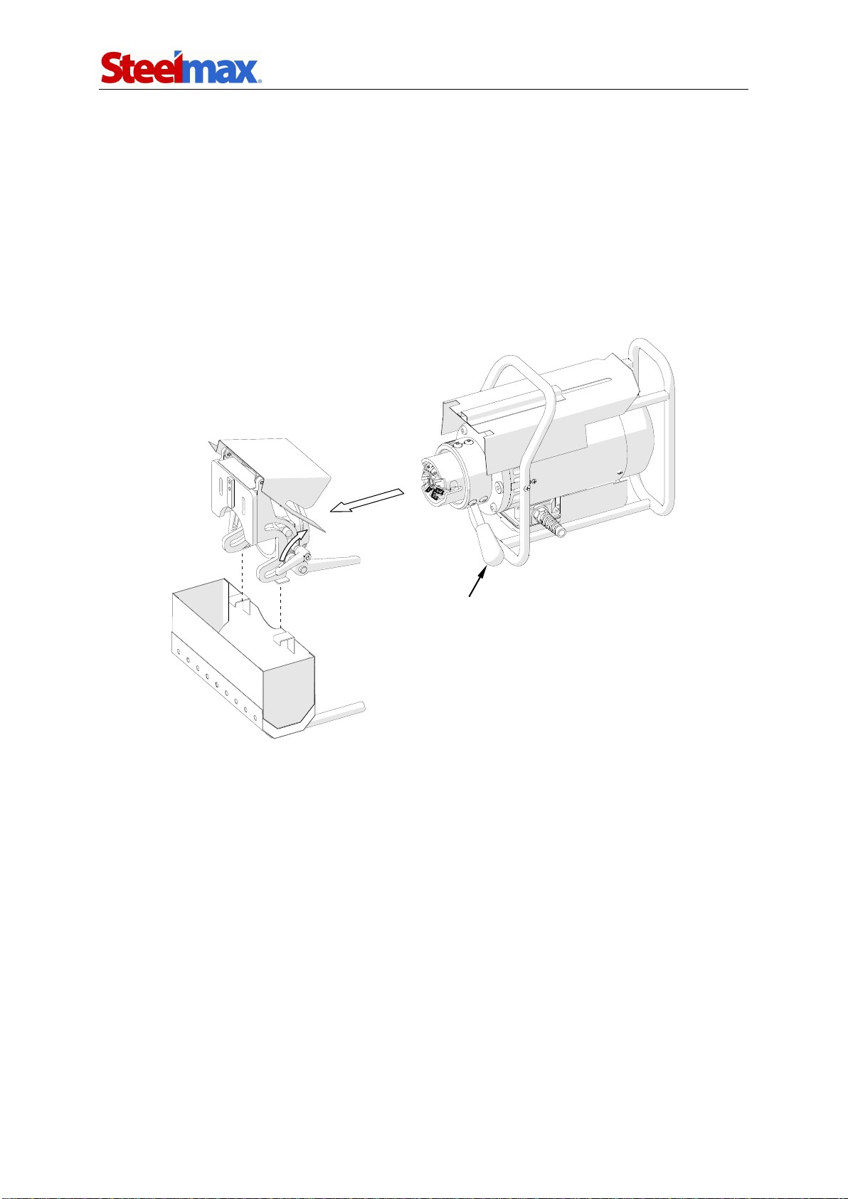
20. After every use, remove chips from the machine, especially from the milling head.
Do not remove chips with bare hands. Clean the machine with a cotton cloth
without using any agents.
21. Carry the chip container using the handles.

ABM-28
ABM-28 Operator’s Manual
8
22. Cover steel parts with a thin anti-corrosion coating to protect the machine from
rust when not in use for any extended period.
23. Maintain the machine and install/remove parts and tools only when the machine
is unplugged from the power source.
24. Repair only in a service center appointed by the seller.
25. If the machine falls from any height, is wet, or has any other damage that could
affect the technical state of the machine, stop the operation and immediately
send the machine to the service center for inspection and repair.

ABM-28
ABM-28 Operator’s Manual
9
3. STARTUP AND OPERATION
3.1. Assembling
The carriage set on the guide in the leftmost position must be placed on the plate
between twoclamps inthe manner shown in Fig. 3a. If needed, extend the guide length
by connecting additional guide segments, and tighten the set screws using the 4 mm
hex wrench (Fig. 3b). Then, install the protective screws 1and 2at the both ends of
the guide, and position the guide using track clamps in such a way to align the track
clamps with respective surfaces of the guide and plate. Fix the track clamps using
levers (3, 4, 5), and tighten the clamp screws by rotating the clamping rods (6,7). To
adjust the pressing force of the track clamps depending on the plate thickness, use
the adjusting screws 8which can be located in one of three track clamp holes.
Fig. 3. Placing the machine on the plate (a); installing additional guide segments (b)
5
3
7
6
a)
4
1
2
11
9
10
8
b)
Set screw

ABM-28
ABM-28 Operator’s Manual
10
If the plate is to be machined at a negative angle (from the bottom), loosen two
milling unit support screws using the 4 mm hex wrench and set the indicator to the
value of the plate thickness (9). Position the milling unit support on the screws (10),
in the shown order place the washers under the nuts (11), and tighten the nuts using
the 13 mm flat wrench.
Set the lever 1in the position as in Fig. 4, insert the milling unit horizontally into
the support (2), and lock the bevel depth lock lever (3). If the plate is to be machined
at a positive angle (from the top), set the chip container on the brackets (4).
Fig. 4. Installing the milling unit
2
3
4
1

ABM-28
ABM-28 Operator’s Manual
11
3.2. Setting the bevel parameters
Loosen the lever 1(Fig. 5), rotate the lever 2to set a proper milling head penetration
in the workpiece indicated on the scale 3(one graduation equals 1 mm, 0.04’’), and
then lock the position using the lever 1.
Fig. 5. View of the milling unit
Next, loosen the levers 4and 5, rotate the milling unit in such a way to set
a proper bevel angle on the scale 6, and then lock the levers 4and 5.
Start beveling with the milling head retracted as far as possible, especially when
milling at the angle of 0°.
Proceed with caution if the milling unit is inclined at ahigh negative angle. In such
a case when readjusting the milling head penetration near the maximal retraction,
hold the handles tightly not to allow the milling unit to slip down from the support after
the bevel depth lock lever 1is unlocked.
1
3
2
6
5
4

ABM-28
ABM-28 Operator’s Manual
12
3.3. Operating
Plug the milling unit power cord into the socket 1(Fig. 6), and connect the cord 2to
the power source. Then, set the power switch 3to the position ‘I’ and use the knob 4
to change the travel speed of the carriage to the least possible value. Select “right”
direction of the travel using the switch 5, and start the motor with the button 6.
Fig. 6. View of the control panel
After the travel is started, set aspeed that will ensure sufficient milling performance
and prevent the overload of the motor and excessive wear of the cutting inserts. Good
effects are achieved with a speed at which the overload lamp 7will not flash.
The plate must be at all times pressed by two track clamps positioned as close to
the current position of the carriage as possible. When the carriage approaches the
track clamp, relocate the track clamp to the other side of the carriage.
Establish bevels in several passes and not exceed 4 mm (0.16’’) of the milling
head penetration d(Fig. 1) in a single pass. When the carriage reaches the plate
end, either toggle the switch 5to the opposite travel direction or first stop the carriage
with the button 8and then readjust the bevel depth or angle.
In an emergency, use the emergency switch 9to shut off the power. To restart
the operation in such a case, remove the cause of the shutdown, unlock the
emergency switch, and start the machine using the button 6.
If the speed is too high for the bevel width and depth that are set, the machine will
stop and start cyclically. In such a case, decrease the travel speed or milling head
penetration in the workpiece.
1
2
3
4
5
6
7
8
9

ABM-28
ABM-28 Operator’s Manual
13
If the machine becomes overloaded, for instance when the bevel width is too
large for the material being machined, when the cutting inserts are dull, or when the
travel speed and bevel depth are too high, the spindle will stop automatically. In such
acase, hold the button 6, which will start the travel in the opposite direction and
enable the operator to retract the milling head from the workpiece. Next, release the
button 6,press the button 8,and then remove the cause of the shutdown and restart
the motor using the button 6.
If the carriage stops as a result of reaching one of the protective screws, set the
switch 5to the opposite travel direction before restarting.
Operating near the overload (with the overload lamp flashing) is allowed; however,
never allow the motor temperature to exceed 85°C (185°F) because this can lead to
damage of the motor windings. After every hour of operating under full load, stop the
motor for 10–15 minutes. Never cool the motor by running without load because it will
become heated even faster than when working with load.
After the work is finished, stop the motor using the button 8, set the power switch
to the position ‘O’, and then unplug the power cord from the power source.
Clean the machine with a cotton cloth without using any agents.

ABM-28
ABM-28 Operator’s Manual
14
3.4. Replacing the cutting inserts
The inserts may be replaced or rotated. To do this, unplug the power cord from the
power source and unplug the cable connecting the milling unit to the carriage. Next,
loosen the bevel depth lock lever (1, Fig. 7), set the lever 2in the position shown in
the figure, and then remove the milling unit (3).
Fig. 7. Removing the milling unit
Next, unscrew the set screw in the manner shown in Fig. 8, remove the insert,
and clean the socket. Next, rotate the insert by 90° and install again or replace with
a new one if all four edges are worn, securing with the set screw.
Fig. 8. Replacing the cutting inserts
1
3
2

ABM-28
ABM-28 Operator’s Manual
15
3.5. Replacing the milling head
Unplug the power cord from the power source, and unplug the cable connecting the
milling unit to the carriage. Remove the milling unit in the manner shown in Fig. 7,
hold the spindle lock button, and use 5 mm hex wrench to loosen the screw (Fig. 9).
Then, release the lock button and remove the head. Install in reverse order.
Fig. 9. Replacing the milling head
Fixing screw
Spindle
lock
button

ABM-28
ABM-28 Operator’s Manual
16
3.6. Using optional milling unit supports
To install a milling unit support, unplug the power cord, unplug the cable connecting
the milling unit to the carriage, and remove the milling unit as shown in Fig. 7.
Then, unscrew the nuts using the 13 mm flat wrench (1, Fig. 10), and remove the
installed support (2). Before installing the support for beveling 36–70 mm thick plates
at the angle of 0° to –60°, loosen two screws (3) using the 4 mm hex wrench and set
the indicator to the thickness of the plate to be machined. Position the milling unit
support on the screws (4), in the shown order place the washers under the nuts (1),
and tighten the nuts afterward.
Fig. 10. Replacing the milling head support
Support
–60° to +60°
Support
0° to +60°
1
2
4
3
8
9
6
5
7
Support for J-beveling
Support
0° to –60°

ABM-28
ABM-28 Operator’s Manual
17
To install the support for J-beveling, loosen the screw 5using the 8 mm hex
wrench and loosen two lock levers 6, set the body to a proper height indicated by the
scale 7, and tighten the screw and levers. Then, install the milling head for J-beveling
in the manner shown in Fig. 9.
Install the milling unit in the manner shown in Fig. 4.
To face the plate using the support for beveling 36–70 mm plates at the angle of
0° to +60°, perform the first pass with the milling unit in the lowest position (8,
Fig. 10), and then the second pass at the indication of ‘0’ (9).
Before J-beveling, prepare the plate as shown in Fig. 11 using the standard milling
head. Then, replace the milling head to a special R6 or R8 milling head for J-beveling.
During J-beveling, the carriage must travel to the left, which will reduce vibrations,
increase the life of the cutting inserts, and improve the quality of the surface. When
performing multiple passes, before every next pass, place the carriage again on the
right side of the plate, and increase the penetration of the milling head in the workpiece.
Establishing J-bevels may require several stages (Fig. 11) depending on the plate
thickness. After completing every stage, lower the milling unit, secure the support in
this new position, and perform the next stage. Proceed as described until the J-bevel is
established.
Fig. 11. Sample method of J-beveling of 20-70 mm plates
Stage 2
Stage 1
Pass 1
Pass 2

ABM-28
ABM-28 Operator’s Manual
18
4. ACCESSORIES
4.1. Support for beveling 36–70 mm plates at 0° to 60°
4.2. Support for beveling 36–70 mm plates at 0° to –60°
Part number:
WSP-0518-04-00-00-0
Part number:
WSP-0518-05-00-00-0

ABM-28
ABM-28 Operator’s Manual
19
4.3. 1.2 m (47’’) guide track
4.4. Support for J-beveling 20–70 mm plates
Part name
Part number
J-beveling R6 milling head (with fixing screw SRB-000284
and retaining ring PRS-000006; without cutting inserts,
6 required)
GLW-0518-07-03-00-0
Cutting insert for J-beveling R6 milling head
PLY-000422
J-beveling R8 milling head (with fixing screw SRB-000284
and retaining ring PRS-000006; without cutting inserts,
5 required)
GLW-0518-07-04-00-0
Cutting insert for J-beveling R8 milling head
PLY-000424
Part number:
ZSP-0518-13-00-00-0
Part number:
ZST-0518-07-00-00-0
(includes: milling unit support for
J-beveling WSP-0518-07-01-00-0 and
chip guard OSL-0518-07-02-00-0)

ABM-28
ABM-28 Operator’s Manual
20
4.5. Clamp for 36–70 mm plates
4.6. Track clamp for 36–70 mm plates
Part number:
ZCS-0152-99-01-00-0
(2 required)
Part number:
UST-0152-15-01-00-1
(3 required)
Table of contents
Other SteelMax Industrial Equipment manuals