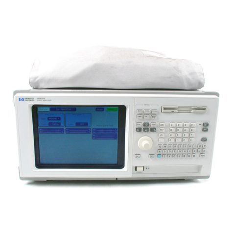
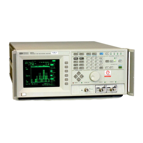
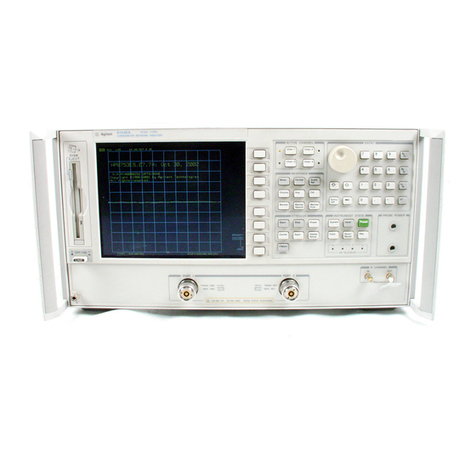
HP HP 8902A User manual

$JLOHQW7HFKQRORJLHV,QF
(0LVVLRQ
/LEHUW\/DNH:$
ZZZDJLOHQWFRP
-XQH
Dear Customer,
As of November 1, 1999, four of Hewlett-Packard’s businesses, test and measurement,
semiconductor products, health care solutions, and chemical analysis became a new company,
Agilent Technologies. Now, many of your Hewlett-Packard products and services are in the care of
Agilent Technologies.
At Agilent Technologies, we are working diligently to make this transition as smooth as possible for
you. However, as a result of this transition, the products and related documentation contained in this
shipment may be labeled with either the Hewlett-Packard name and logo, the Agilent Technologies
name and logo, or a combination of both. Information in this package may refer to Hewlett-Packard
(HP), but applies to your Agilent Technologies product. Hewlett-Packard and Agilent branded
products with the same model number are interchangeable.
Whatever logo you see, the information, products, and services come from the same reliable source.
If you have questions about Agilent Technologies products and services, please visit our website at
http://www.agilent.com.
6LQFHUHO\
5HEUDQGLQJ7HDP

QUICK
REFERENCE
GUIDF
HP
8902A
MEASURING
RECEIVER
HEWLETT
PACKARD
8902A Operation and Calibration Manual
Part Number 08902-90029

--
--
<VI
AUDIO
AVO
OETECTW
SENSOR
MODULE
\
Slow
Fast
6.0 6.1
AM
>
20
Hz
AM
>
1
kHz
Tuoy
Off
6.2
-
DlSTWTlDN
AUDIO
WS
ANALYZER
DETECTOR
SY”0US
DETECTOR
CHANNEL
IF
Ws
1
FILTERS ETECTW
ERROR
MESSACE
B-
DISABLE
AUDIO
ry
IF
PEAK
]zHDIESJh
COUNTER
DETECTOR (OPTION
038
VOLTABE-TO-TIME
CONVERTER
SERIES
ONLY)
\
-A
RF
Gain
(dB)
RF
Attenuation
(dB)
0
10 20 30 40 50
24
14
1.0 1.1 1.2 1.3 1.4 1.5 1.6 1.7 1.8
AUTO’
1.9
ExceptTuned
RF
Level

2.
Audio Range
AUTO
7.0
7.
RF Frequency Resolution
10
Hz
100
Hz
1
kHz
1
Hz
7.1 7.2 7.3 7.4
Modulation
AM
("10,
pk)
01 01
01
02 02 02 02
03
03 03 03
04 04 04 04
8.2 8.3 8.4 8.5 8.6 8.7
I
Detector
I
All
Errors
Enabled
8.8
Pk,
Ave, RMS
Auto
400
01 01
01
02 02 02 02
03
03 03 03
04 04 04 04
8.2 8.3 8.4 8.5 8.6 8.7
@M(rad, pk)
0.4
4
400
2.0 2.4
2.1
(2.4)
2.2
I
2.3
*
Divide-by-10with
750
ps
FM DE-EMPHASIS and PRE-DISPLAY.
All
Errors
Enabled
8.8
IF FREQ
I
I
I
I
455 kHz
[
1.5 MHz
Bandwidth
I
Wide Filter
I
Auto
I
2.5
MHz
I
200
kHz
I
2.5
Ma
Narrow Filter
RF
HP Filter Out
RF HP Filter In
I
4
I
1
30
kHz Bandwidth NarrowFilter Out
3.0 3.6 3.5
3.1
3.2
3.8
3.7
3.3 3.4
Auto
0
10
20 30 40
9.0 9.1 9.2 9.3 9.4 9.5
4.
Tuned RF Level Detector
Selection and Display Averaging
50 60
9.6 9.7
I
Detector
I
IFSvnchronous
I
IFAveraae
1
Auto
0
10
20 30 40
9.0 9.1 9.2 9.3 9.4 9.5 50 60
9.6 9.7
5.
Audio Detector Response
Audio Peak Detector Response and
RMS
Detector Digital
Averaging Response:
I
Fast I
Slow
1
Measurement
AveragingTime@) AUTO
4.0
-1
5.1
10
1
0.1 AUTO 10 1 0.1
4.1
4.2
4.3
4.4
4.5 4.6 4.7
AUTO
#I
#2
#3
#4
10.0
10.1
10.2 10.3 10.4
8.
Error Message Disable and Enable
#5
10.5
I
DisableErrors
I
9.
IF
Gain
70.
RF Power Range
77.
Previous Ratio
1
1.2
Display previous ratio reference.

72/73.
Calibration FM, AM
Computed
Residual
Measured
Display Peak
FM
Display Peak AM
12.0 13.0
12.1 13.1
12.2 13.2
74.
Limit
Set
to
Ratio
Reference
Enable
Display
Display
Measurement Code
14.0
Disable
Lower Limit Upper Limit
14.1 14.2
14.3 14.4
14.5 14.6
14.7 14.8
14.9
Display limit status: Lower limit status. Upper (O=disabled,
1
=enabled).
Disable
Enable
Display
AM
Cal Factor FM Cal Factor
16.0
17.0
16.1 17.1
16.2 17.2
75.
Time Base Check
15.0
Displays Error
12
if Option
002
is installed and oven is cold.
Displays
0
if Option
002
is installed and oven
is
warm, or if
Option
002
is not installed.
Displays
0
if internal time base is being used. Displays
1
if
external time base is being used.
15.1
7
6.
Calibration Factors:
AM,
7
7.
Calibration Factors: FM
7
8.
Tone-Burst Receiver
18."
Configures instrument as a tone-burst receiver.
A
time delay
of NN ms is inserted between detection of a carrier and
unsquelching of the output at MODULATION OUTPUT/AUDIO
INPUT. Range of NN is
1
to
99
ms.
If
NN is
0,
delay is
99
ms.
2

21. HP-lBAddress
Establish
Select
dB
24.1 24.2
24.3 24.4
24.5 24.6
21.0
Displays HP-IB address in form AAAAAAA.TLS
AAAAAAA
=
binary address
T
=
1
=
talk only
L
=
1
=
listen only
S
=
1
=
requesting service
Display
Normalize
Noise Meas.
24.7
22. Service Request
22,"
A
value of
NN
from
0
to
63
sums the weighted conditions below
to set up a service request mask. The summed, weighted
conditions are displayed when
NN
is
64.
1
Data Ready
2
HP-IB error (Cannot be disabled.)
4
Instrument error
8
Limit exceeded
16
Frequency Offset mode state change
32
Recal or Uncal
64
Read back SRQ mask
23. External
LO
(Option
030
Only)
23.0
23.1
23.2
Return the
LO
to internal.
Set the
LO
to external.
Display LO status:
(0
=
Internal,
1
=
External)
24. Selective Power Measurement (Option 030 Only)
24.0
Sets the Measuring Receiver to the Selective Power Measurement
Mode.
Wide BW IF Filter
(Adjacent-Channel, Cellular)
Narrower BW IF Filter
(Adjacent-Channel)
Narrowest BW IF Filter
(Single-Sideband Noise)
24.8
24.9
Sets the value of the noise measurement
BW.
Display the value
of
the noise measurement
BW.
25.
External Attenuation
(dB)
25.2
Display attenuation value.
3

26. Set Reference
Frequency Offset Mode
Exit Re-enter
27.0 27.1
26.0
Exit attenuator measurement
26.1
Re-enter attenuator measurement
External
LO
Display Enter/Enable
27.2 27.3
27. Frequency Offset Control
29/30. Other Audio Measurement Modes
29.0
SINAD
30.0
EXT
AUDIO RMS
LEVEL
31. Tuned
RF
Level Noise Correction
31.0
Turn
off
noise correction.
31.1
Turn on noise correction.
31.2
Dipslay noise correction status
(1
=
Off,
0
=
On).
32. dB and Frequency Resolution
32.0
Normal measurement resolution (Power:
0.01
dB resolution)
(Audio Frequencies from
100
to
250
kHz;
0.1
Hz
resolution).
Increased measurement resolution (Power:
0.001
dB resolution)
(Audio Frequencies form
100
to
250
kHz;
0.1
Hz
resolution).
Display measurement resolution status.
(0
=
normal,
1
=
increased.
32.1
32.2
32.9 Tuned RF Level Measurements Using Track-Mode Tuning
1.
Input a signal greater than
-30
dBm.
2.
Select
32.9
SPCL.
3.
If
using an external
LO,
enter the external LO frequency in
MHz.
4.
Select
MHz
to enter the manual tune mode.
5.
Step the signal generator down in amplitude and press the
CALIBRATE key whenever the RECAL annunciator is displayed.
4

33/36.
Other Measurement Modes
Display
Enter
33.0
LO FREQUENCY
34.0
IF
FREQUENCY
35.0
RFLEVEL
36.0
PEAK TUNED
RF
LEVEL
RF
Power
to
Range Range
SET REF
Range
1 1
to
2 2
to
3
Reference
38.1
38.2 38.3 38.4
39.1 39.2 39.3 39.4
37.
Calibration Factors:
RF
Power
37.0
Automatic Cal Factors
37.1
Manual Cal Factors
37.2
37.3
*Enter frequency, cal factor
37.4
*Display table size
37.5
*Recallreference cal factor
37.6
37.7
*Clear Table
Display Status
(0
=
auto,
1
=
held)
*Recallnext frequency, cal factor
*
Two
tables are available. The table being used
is
determined by the status
of the Frequency Offset mode (Special Function
27).
38/39. Calibration Factors Tuned RF Level
39.9
Clear all calibration factors.
5

Frequency Offset (Special Function
27).
The Frequency Offset mode allows the Measuring Receiver to keep
track of frequencies involved in the down-conversion process. This
frequency offset process is used in conjunction with an external mixer
and Local Oscillator
(LO)
to extend the frequency coverage above
1300 MHz.
To
enter the Frequency Offset mode:
+
LO Frequency
+
Fl
To
exit the Frequency Offset mode:
To
re-enter the Frequency Offset mode with the same
LO
frequency:
To
display the external
LO
frequency:
6

Display
Code
-
-
or
0
MHz
----
------
01
02
03
04
05
06
07
08
09
10
To Solve an Input Problem
To
Solve an OperatingProblem
Adjust input signal level or change
measurement sensitivity. Decrease RF attenuationor gain.
Re-check operating conditions being
used.
I
Manually tune to input signal.
Check tuning. Re-check special operating conditions
being used.
Increase input signal level or decrease
AM.
Increase RF input attenuation.
Increase level of input signal.
Press the MHz key to center IF signal
in IF passband.
If
problem persists, signal may be
drifting.
Decrease RF and/or IF gain setting.
Decrease selected
RF
input attenuatior
or increase IF gain.
If
Range Hold is being used, check
range limits.
Decrease modulation level on input
signal to within measurement range. Increase range limit setting, Special
Function
2.N.
Increase carrier level or decrease AM
depth
(<go%).
I
Input level exceeds
7
Vrms
(1
W peak).
Decrease level of input signal.
If
making a TRFL measurement, also
press the CLEAR key.
Decrease selected RF or IF gain.
If
Range Hold is being used, check
range limits.
Decrease modulation level on input
signal.
If
making a TRFL measurement,
decrease level of input signal and pres
CLEAR key.
Decrease selected RF or IF gain.
If
Range Hold is being used, check
range limits.
I
I
I
Check connection to Calibrator.
Check for Calibrator malfunction.
I
I
Check internaltime base for
malfunction(Option
002
only).
I
Adjust frequency of input signal to
within measurement range, or increase
measurement range.
If
making a TRFL measurement, set thc
input level to between
0
and
-20
dBm.
Select the Frequency mode. When the
instrument displays the frequency of
the input signal, press the MHz key an(
re-enter the TRFL mode.
I
7
Operating
Error
Codes
Display
Code
11
12
13
14
15
16
17
18
19
20
21
22
23
24
25
26
To Solve an Input Problem
Select linear (Watts) units, or disregard
error when there is no power present
at sensor input.
Secure connection at SENSOR input.
Increaseaudio signal level.
Input signal level during reference
measurement must be between 1.29’
and 2.5QV.
To
Solve an OperatingProblem
Key in a different ratio reference.
Wait for oven to warm for highest
accuracy.
Remove power from power sensor
input during zeroing process.
Verify that cal factors have been
entered.
Check selected RF or IF gain level.
(When making Ratio measurements,
allow instrumentto complete the
reference measurement.)
Check sensor connection at RF
POWER OUTPUT port.
Increase IF gain.
Re-enter frequency within measuremen
range. (In Ratio mode, a reference
measurement of zero is invalid.)
Check compatibilityof function(s) with
selected measurement mode.
Check Special Function number and
re-enter (prefix invalid).
Check Special Function number and
re-enter (suffix invalid).
Invalid HP-IB code. Check function
codes.
Check Special Function Compatibility
with measurement.
End of RF Power calibration table. (If
displayed after first attempt to read
table using
37.6
SPCL, the table is
empty.)
8

Display
Code
30
31
32
33
34
35
To
Solve an Input Problem
Maintain stable frequency and level
during calibration.
Check
SENSOR
connection.
To Solve an Operating Problem
Change RF attenuation and gain or
Range Hold setting.
Calibrate RF Power measurement.
Change IF gain or Range Hold setting.
Check
RF
Power calibration.
Maintain stable frequency during TRFL
calibration.
Use a stable signal source for TRFL
calibration.
9

Measuring Receiver finction to
Code
Summary
Function
MEASUREMENTS
AM
FM
@M
RF POWER
FREQ
AUDIO FREQ
AUDIO DlSTN
IF LEVEL
TUNED RF LEVEL
FREQ ERROR
DETECTORS
PEAK+
PEAK HOLD
AVG (RMS Calibrated)
1 kHz DlSTN
400 Hz DISTN
RMS
PEAK&/2
PEAK-
DISPLAYS
Display LOG Result
Display LIN Result
dB EXT ATTEN
off
dB EXT AlTEN on
RATIO
Off
RATIO On
PREVIOUS RATIO
FILTERS
HP (High-Pass) FILTERS
Off
50 Hz FILTER On
300 Hz FILTER On
LP (Low-Pass) FILTERS
Off
3 kHz FILTER On
15 kHz FILTER On
>20 kHz FILTER On
FM
DE-EMPHASIS
PRE-DISPLAY
Off
and
PRE-DISPLAY On and
FM DE-EMPHASISOn
FM DE-EMPHASIS
Off
25
PS
DE-EMPHASIS
50
PS
DE-EMPHASIS
75
PS
DE-EMPHASIS
750
ps
DE-EMPHASIS
Code
M1
M2
M3
M4
M5
s1
s2
s3
s4
s5
D1
D2
D3
D4
D5
D6
D8
D9
LG
LN
NO
N1
RO
R1
R2
HO
H1
H2
LO
L1
L2
L3
PO
P1
P2
P3
P4
P5
CALIBRATION
CALIBRATE
Off
CALIBRATEOn
Yo
CAL FACTOR
SET REF
ZERO
SAVE CAL
MANUAL OPERATIONS
AUTO TUNING
ENABLE ERRORS
DISABLE ERRORS
CLEAR (KEY)
BLUE KEY, CLEAR (KEY)
DISPLAY FREQ
DISPLAY INCREMENT
INPUT FREQUENCY (Hz)
fi
Hz
u
Hz
TRACK Mode
Off
(Lock Mode)
TRACK Mode On
fi
kHz
4)
kHz
MHz (INPUT FREQ)
RECALL
STORE
SPECIAL FUNCTION
SPECIAL, SPECIAL
mV Units
pV
Units
V Units
W Units
MISCELLANEOUS
MODULATIONOUTPUT
AUDIO INPUT
AUTOMATIC OPERATION
Auto-Ranging (RANGE HOLD
Off)
RANGE HOLD
Identify Instrument
INSTR PRESET (same as DCL)
Trigger Off
Hold
Trigger Immediate
Trigger with Settling
HexidecimalA
Hexidecimal
B
HexidecimalC
Hexidecimal
D
Hexidecimal E
Hexidecimal F
Code
co
c1
CF
RF
ZR
sc
AT
BO
B1
CL
BC
FR
FN
HZ
HU
HD
KO
K1
KU
KD
MZ
RC
TR
SP
ss
MV
uv
VL
WT
A0
A1
AU
GO
G1
ID
IP
TO
T1
T2
T3
xo
x1
x2
x3
x4
x5
10

Code
to
Measuring Receiver finction
Summary
Code
A0
A1
AT
AU
BO
B1
BC
co
c1
CF
CL
D1
D2
D3
D4
D5
D6
D8
D9
FR
FN
GO
G1
HO
H1
H2
HU
HD
HZ
ID
IP
KO
K1
KU
KD
LO
L1
L2
L3
LG
LN
Function
MODULATION OUTPUT
AUDIO INPUT
AUTO TUNING
AUTOMATIC OPERATION
ENABLE ERRORS
DISABLE ERRORS
BLUE KEY, CLEAR (KEY)
CALIBRATE
Off
CALIBRATE On
Yo
CAL FACTOR
CLEAR (KEY)
PEAK+
PEAK HOLD
AVG (RMS Calibrated)
1 kHz DISTN
400 Hz DISTN
RMS
PEAKf/2
DISPLAY FREQ
DISPLAY INCREMENT
Auto-Ranging (RANGE HOLD
Off)
RANGE HOLD
HP (High-Pass) FILTERS Off
50
Hz FILTER On
300 Hz FILTER On
PEAK-
-Tr
Hz
u
Hz
INPUT FREQUENCY (Hz)
Identify Instrument
INSTR PRESET(same as DCL)
TRACK Mode Off (lock mode)
TRACK Mode On
kHz
kHz
LP (Low-Pass) FILTERS Off
3 kHz FILTER On
15
kHz FILTER On
>20 kHz FILTER On
Display LOG Result
Display LIN Result
Code
M1
M2
M3
M4
M5
MV
MZ
NO
N1
PO
P1
P2
P3
P4
P5
RO
R1
R2
RC
RF
s1
s2
s3
s4
s5
sc
SP
ss
TO
T1
T2
T3
TR
uv
VL
WT
xo
x1
x2
x3
x4
x5
ZR
Function
AM
FM
(PM
RF POWER
FREQ
mV Units
MHz (INPUT FREQ)
dB EXT ATTEN
Off
dB EXT ATTEN On
PRE-DISPLAY
Off
and
PRE-DISPLAY On
and DE-EMPHASIS On
FM DE-EMPHASIS
Off
25
PS
DE-EMPHASIS
50
PS
DE-EMPHASIS
75
PS
DE-EMPHASIS
750
/AS
DE-EMPHASIS
RATIO
Off
RATIO On
PREVIOUS RATIO
RECALL
SET REF
AUDIO FREQ
AUDIO DISTN
IF LEVEL
TUNED RF LEVEL
FREQ ERROR
SAVE CAL
SPECIAL FUNCTION
SPECIAL, SPECIAL
Trigger
Off
Hold
Trigger Immediate
Trigger with Settling
STORE
pV Units
V Units
W Units
Hexidecimal A
Hexidecimal B
Hexidecimal C
Hexidecimal D
Hexidecimal E
Hexidecimal F
ZERO
11

HP
8901A/02A
Code
Differences
HP
8901A
A1 (or AU)
F1 (or MZ)
F2 (or KU)
F3 (or KD)
F4 (or 24 or SP)
F5 (or 25 or
SS)
K1 (or CL)
U1 (or D1)
U2 (or D2)
U3 (or D3)
U4 (or D4)
Z1 (or HZ)
22 (or HU)
23 (or HD)
M4
s4
R1
R2
4.0SP
4.1SP
4.2SP
7.1SP
7.2SP
9.OSP
1O.OSP
11.OSP
11.1SP
11.3SP
15.0SP
Status
Byte
HP
8902A
AU
MZ
KU
KD
SP
ss
CL
D1
D2
D3
D4
HZ
HU
HD
35.0SP
36.0SP
LN,
R1
LG, R1
AT, KO
AT, K1
MZ, KO
7.1SP
7.3SP
G1
34.0SP
LN, R2
LG, R2
use
"-"
key
15.0SP
Status
Byte
Functions
AUTOMATIC OPERATION
MHz (INPUT FREQ)
fi
kHz
4
kHz
SPECIAL
SPECIAL, SPECIAL
CLEAR
PEAK+
PEAK HOLD
Average Detector (RMS Calibrated)
Hz INPUT FREQ
PEAK-
fi
Hz
u
Hz
Peak RF Level
Peak Tuned RF Level
O/o
RATIO
dB RATIO
Auto Tuning, low-noise lock mode
Auto Tuning, track mode
Manual Tuning, low-noise lock
mol
10
Hz frequency resolution
1000 Hz frequency resolution
Hold Setting (RANGE HOLD)
IF Frequency
O/o
PREVIOUS RATIO
dB PREVIOUS RATIO
Make Ratio Reference Negative
e
Oven Check (returns
"0
if oven OK or not
installed, rather than doing nothing as in
the 8901A)
Status Byte Bits "Upper Limit" (weight 8)
and "Lower Limit"(weight
16)
are merged
together into "Limit Reached"(weight 8)
12

Agilent Technologies. Inc www.agtlent.com
24001
E
Mission
Liberty take, WA
99019
*.
.
.::%;.
.
Ag
i
len
t
Techno
log
ies
*.*:*.*
.
!
.
Innovatingthe
HP
Way
June
8,2000
Dear Customer,
As
of
November
1,
1999,
four
of
Hewlett-Packard’sbusinesses, test and measurement,
semiconductor products,health care solutions, and chemicalanalysis became a new company,
Agilent Technologies. Now, manyof your Hewlett-Packardproductsand services are in the care
of
Agilent Technologies.
At Agilent Technologies, we are working diligentlyto make this transition as smooth as possible
for
you. However, as
a
result of this transition, the products and related documentationcontained in this
shipment may be labeled with either the Hewlett-Packardnameand logo, the Agilent Technologies
name and logo, or a combination of both. Information in this package may refer to Hewlett-Packard
(HP), but applies to your Agilent Technologies product. Hewlett-Packardand Agilent branded
products with the same model number are interchangeable.
Whatever logo you see, the information, products, and servicescome from the same reliable source.
If you have questions about Agilent Technologies productsand services, please visit our website at
http://www.agilent.com.
Sincerely,
RebrandingTeam

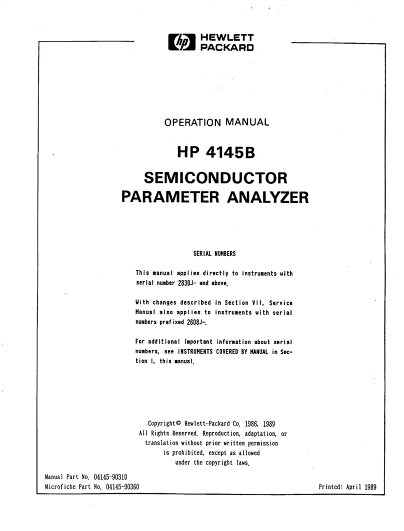
HP
8902A
MEASURING
RECEIVER
Operation and Calibration Manual
SERIAL
NUMBERS
This
manual
provides complete information for
in-
struments
with
serial-numberprefixes:
2305A to 29148
and
all
MAJOR
changes
that
apply
to
your
instrum
ent.
rev.
01
OCT92
numbers, refer to "INSTRUMENTSCOVERED
BY
THLS
MANUAL"
in
Section
1.
Sixth
Edition
This material may
be
reproduced
by
or for the
U.S.
Government pursuant to the Copyright License
un-
der
the
clause at
DFARS
52.227-7013
(APR
1988).
CopyrightOHEWLETT-PACKARD
COMPANY 1985
EAST 24001
MISSION
AVENUE, TAF C-34, SPOKANE, WASHINGTON, U.S.A. 99220
Operation and CalibrationManual HP Part 08902-90029
Other Documents Available:
Basic Operationand ApplicationGuide HP Part 5953-8458
Quick ReferenceGuide HP Part 08902-90060
Service Manual HP Part 08902-90031
Microfiche Operation and CalibrationManual HP Part 08902-90030
MicroficheService Manual HP Part 08902-90032 Printed in USA.
:
November 1994
HEWLETT
PACKARD

Regulatory Information(UpdatedMarch
1999)
Safety Considerations
GENERAL
Thisproduct and related documentation must be reviewed for familiarization
with
safety
markings and instructions before operation.
Thisproduct
has
been designed and tested in accordance
with
IEC
Publication
1010,
"Safety Requirements for Electronic MeasuringApparatus," andhas been supplied in
a
safe condition.
This
instruction documentation contains information andwarnings which
mustbe followed by the user to ensuresafe operation andto maintain
the
product in
a
safe
condition.
SAFETY
EARTH
GROUND
A
uninterruptible safety earthground must be provided
from
the main power source to the
product input wiringterminals, power cord,
or
supplied power cord
set.
SAFETY
SYMBOLS
A
Indicatesinstrument damage can occur if indicated operatinglimits
are
exceeded.
A
Indicateshazardousvoltages.
&
-
Indicates earth (ground)terminal
WARNING
A
WARNING
note denotesahazard.It calls attention to a procedure,
practice, or the like, which, if not correctlyperformedor adhered to,
couldresult in personal injury.
Do
not proceed beyond
a
WARNING
signuntil the indicated conditions are
fully
understoodand met.
CAUTION
A CAUTION note denotes
a
hazard.
It
calls attention
to
an
operation
procedure, practice, or the like, which, if not correctly performed or adhered
to, could result in damage to or destruction of part or
all
of the product.
Do
not proceed beyond an
CAUTION
note until the indicated conditionsarefully
understood and met.
2
Chapter
1

Regulatory
information(UpdatedMarch
1999)
SafetyConsiderations for this Instrument
WARNING
Thisproduct is
a
SafetyClass
I
instrument (providedwith
a
protectiveearthinggroundincorporated inthe power cord).The
mainsplug shall onlybe inserted in a socket outlet provided with a
protectiveearth contact.Any interruption of the protective
conductorinside or outsideof the product
is
likely tomake the
productdangerous.Intentional interruption isprohibited.
Whenever
it
is
likelythat the protection hasbeen impaired,the
instrument must be made inoperativeand be secured against any
unintendedoperation.
If
thisinstrument istobe energizedvia anautotransformer
(for
voltagereduction),make surethe common terminal
is
connectedto
the earth terminal
of
the power source.
If
thisproduct
is
notused as specified,theprotection provided by
the equipment couldbe impaired.Thisproduct must be used in a
normal condition(inwhich
all
meansforprotection areintact)only.
No
operator serviceableparts inthis product. Refer servicingto
qualifiedpersonnel. To prevent electrical shock, do not remove
covers.
Servicinginstructionsare for use by qualifiedpersonnel only.
To
avoid electricalshock,do not perform any servicingunlessyou are
qualified
to
do
so.
The openingof covers
or
removalof parts
is
likely to expose
dangerousvoltages. Disconnect the product from
all
voltage sources
while it
is
beingopened.
The power cord
is
connected
to
internal capacitorsthat my remain
live
for
5
secondsafter disconnectingthe plug from
its
power supply.
For Continuedprotectionagainst firehazard, replace the linefuse(s)
only with
250
V
fuse(s)
or
the same current rating and type (for
example,normalblow
or
timedelay).Do not use repaired fuses
or
shortcircuited fuseholders.
Alwaysuse the three-prongac power cord supplied with this
product. Failure
to
ensure adequate earth groundingby not using
this cordmay causeproduct damage.
Thisproduct
is
designed
for
use in InstallationCategory
I1
and
PollutionDegree
2
per
ZEC
1010
and
IEC
664
respectively. FOR
INDOOR
USE
ONLY.
This product has autoranginglinevoltage input,be surethe supply
voltage
is
within the specified range.
Chapter
1
3
Other manuals for HP 8902A
1
Table of contents
Other HP Measuring Instrument manuals