UV-1800 SERIES xi
CONTENTS
Chapter 1 General
1.1 UV-1800 Configuration ...................................................................................................................... 1-2
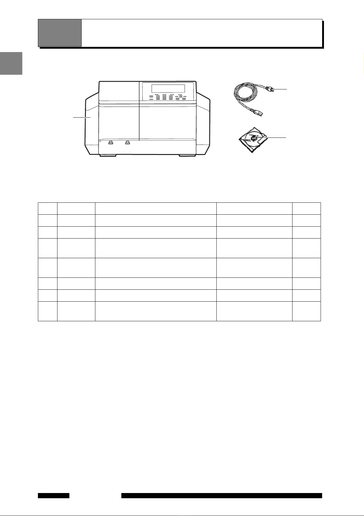
1.2 Components ...................................................................................................................................... 1-3
1.2.1 UV-1800 Main Body, Front and Top Views .......................................................................... 1-3
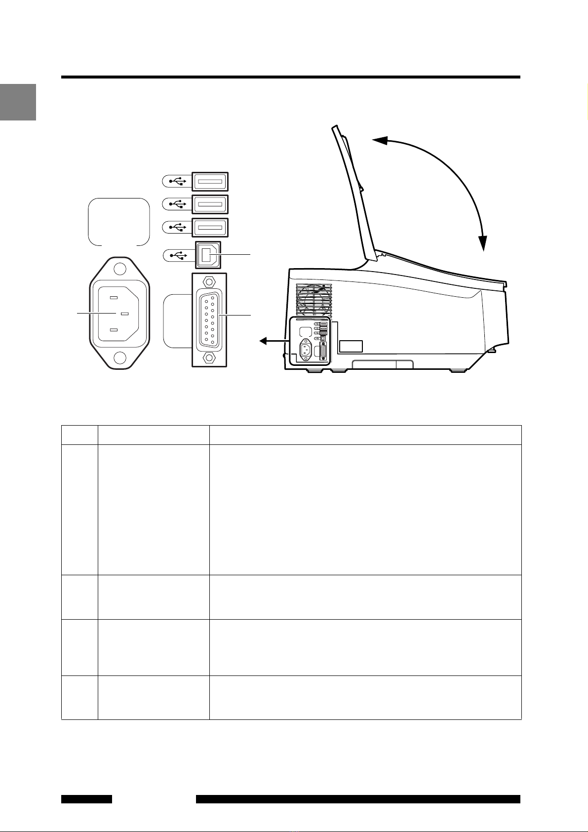
1.2.2 UV-1800 Main Body, Left Side View..................................................................................... 1-4
1.2.3 UV-1800 Main Body, Right Side View .................................................................................. 1-5
1.2.4 Sample Compartment........................................................................................................... 1-6
1.2.5 Keypad.................................................................................................................................. 1-7
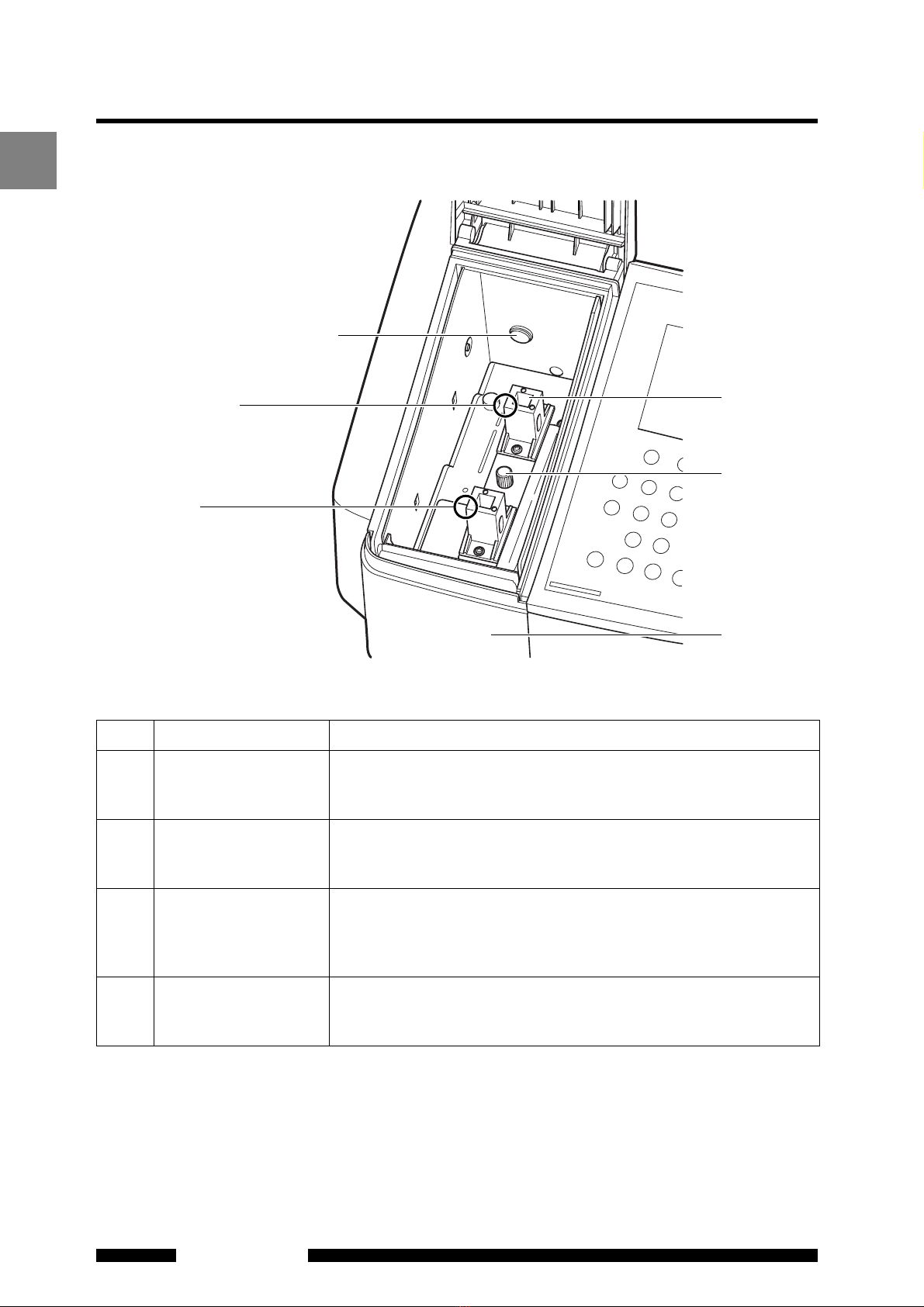
1.2.6 Light Source Compartment...................................................................................................1-8
Chapter 2 Installation
2.1 Installation Site .................................................................................................................................. 2-2
2.1.1 Installation Requirements and Preparation........................................................................... 2-2
2.1.2 Installation Space ................................................................................................................. 2-3
2.2 Connecting Power ............................................................................................................................. 2-4
2.2.1 Verifying Power Supply Voltage ........................................................................................... 2-4
2.2.2 Connecting to the Power Outlet............................................................................................ 2-5
2.2.3 Grounding............................................................................................................................. 2-6
2.3 Checking the Light Source Lamp (D2) .............................................................................................. 2-7
2.4 Operation Precautions....................................................................................................................... 2-8
2.5 Turning ON the Power and Initialization ............................................................................................ 2-9
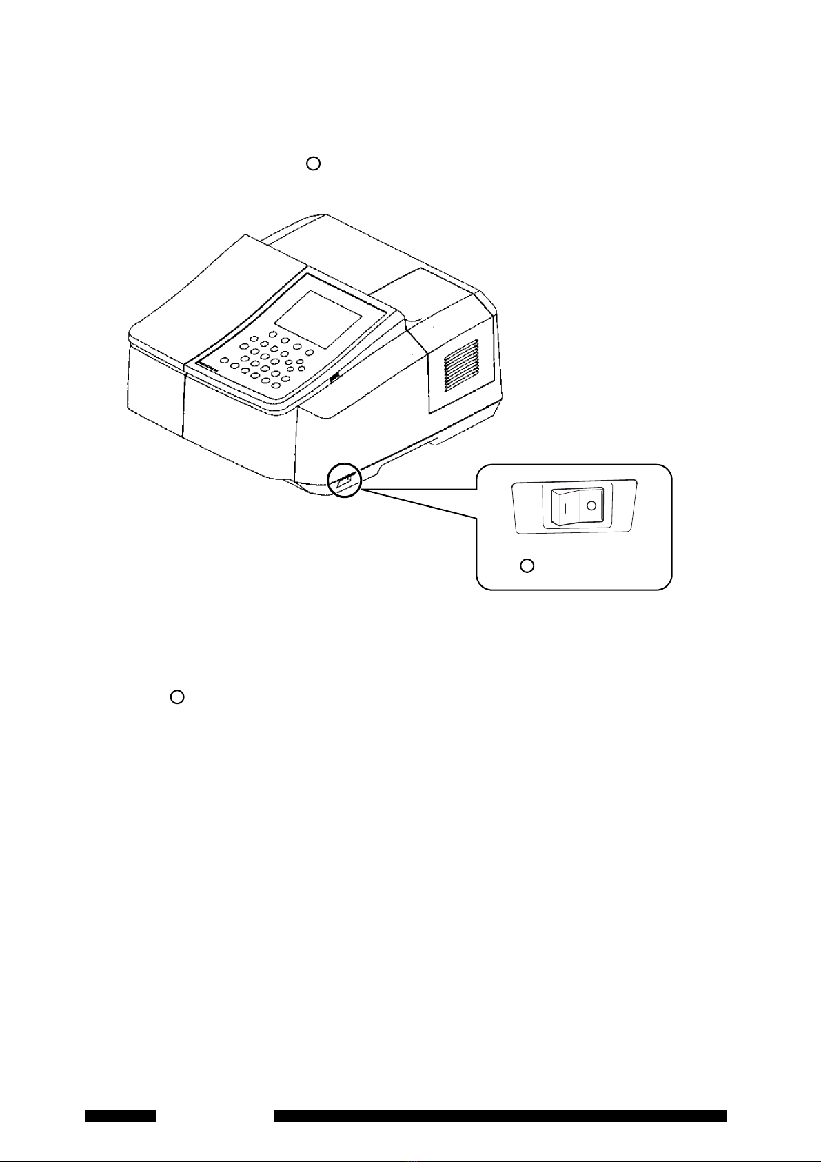
2.5.1 Power ON/OFF ..................................................................................................................... 2-9
2.5.2 Initialization Operation ........................................................................................................ 2-10
2.5.3 Switching System Language .............................................................................................. 2-12
2.6 Instrument Baseline Correction ....................................................................................................... 2-13
2.7 Performance Check after Installation .............................................................................................. 2-15
2.7.1 Parameter Settings ............................................................................................................. 2-15
2.7.2 Performing Validation ......................................................................................................... 2-16
Chapter 3 Maintenance & Inspection
3.1 Inspection and Maintenance.............................................................................................................. 3-2
3.1.1 List of Periodic Inspection & Maintenance Items.................................................................. 3-2
3.2 Inspecting the Sample Compartment ................................................................................................ 3-3
3.3 Checking and Resetting the Lamp Usage Time ................................................................................ 3-4
3.3.1 Checking Procedure ............................................................................................................. 3-4
3.3.2 Resetting Procedure ............................................................................................................. 3-5
3.4 Replacing the Light Source ............................................................................................................... 3-7
3.4.1 Light Source Specifications .................................................................................................. 3-7
3.4.2 Lamp Replacement Procedure ............................................................................................. 3-8
3.5 Cleaning the Exterior ....................................................................................................................... 3-15
Chapter 4 Replacing the Sample Compartment Parts
4.1 Removing/Installing the Cell Holder................................................................................................... 4-2
4.1.1 Removing the Cell Holder..................................................................................................... 4-2
4.1.2 Installing the Cell Holder....................................................................................................... 4-3
4.2 Removing/Installing the Sample Compartment Unit (Standard)........................................................ 4-4
4.2.1 Removing the Sample Compartment Unit ............................................................................ 4-4
4.2.2 Installing the Sample Compartment Unit .............................................................................. 4-5
4.3 Removing/Installing the Sample Compartment Front Cover ............................................................. 4-7
4.3.1 Removing the Sample Compartment Front Cover and Installing the Front Plate................. 4-7
4.3.2 Installing the Sample Compartment Front Cover.................................................................. 4-8