Steffes COMFORT PLUS 4120 User manual
U.S. Pat. #5201024, #5086493
Can. Pat. #2059158, #2060881
Models:
4120, 4130,
& 4140
Applicable to Software Version 2.00-2.19
OWNER'S AND
INSTALLER'S MANUAL
for
Comfort Plus
Forced Air Heating Systems
Equipped with Variable Speed
This manual applies to heating systems
built after 07/01/2019.

The equipment described herein is intended for installation by a qualied technician
in compliance with applicable local, state, and national codes and requirements.
To insure proper installation and operation of this product, completely read all in-
structions prior to attempting to assemble, install, operate, maintain or repair this
product. Upon unpacking of the system, inspect all parts for damage prior to installa-
tion and start-up.
This manual should be retained by the owner upon completion of the installation and
made available to service personnel as required.
This appliance is not to be used by persons (including children) with reduced physi-
cal, sensory or mental capabilities or lack of experience and knowledge, unless they
have been given supervision and instruction on the safe use of the appliance and the
hazards involved. Children shall not play with the appliance.
Disclaimer: In compiling this manual, Stees has used its best judgement based
upon information available, but disclaims any responsibility or liability for any er-
rors or miscalculations contained herein, or any revisions hereof, or which result, in
whole or in part, from the use of this manual or any revisions hereof.
Stees disclaims any responsibility or liability for mold/mildew growth and/or any
damages caused by either which occur after the heating system is installed. We
strongly recommend that the user follow the moisture, mold and mildew prevention
guidelines of the Environmental Protection Agency (EPA), available at http://www.epa.
gov. If you are unable to nd information and have concerns, contact Stees.
IMPORTANT
For Customer Use
located on the lower left side of the 4100 series base. Retain this information for future reference.
Model No. ________________________________________________________________________
Serial No. ________________________________________________________________________
RECOGNIZE THESE SYMBOLS AS SAFETY PRECAUTIONS
It is important, both for your personal safety and to avoid possible damage
to the equipment and your property, that you observe the safety instructions
given following these symbols.

SAFETY PRECAUTIONS
1. Install all ceramic brick and completely assemble the
heating system before energizing the system to avoid
damage to the heating system.
2. DO NOT use or store materials that may produce
3. Maintain all placement and clearance requirements as
safety.
4. Keep the top of the heating system free of debris and
other objects.
5. Disconnect power to all circuits before servicing. This
heating system may be connected to more than one
branch circuit.
6. Installation of and/or service to this heating system
compliance with information contained herein and with
national, state, and local codes and requirements.
7. A repeated message of “CORE FAIL” indicates a need
BUILT-IN SAFETY DEVICES
The Comfort Plus heating system incorporates safety devices to ensure normal operating temperatures are
maintained. The chart below describes these safety devices.
DEVICE NAME FUNCTION LOCATION
ON SYSTEM
Core Charging High
Limit Switches
(Auto Reset)
These limit switches monitor brick core charging and
interrupt power to the heating elements if the normal
operating temperature is exceeded.
This limit switch monitors the discharge air temperature
and interrupts power to the core blower(s) if the normal
operating temperature is exceeded:160oF (nominal).
Core Blower
Limit Switch
(Auto Reset)
This limit switch monitors the discharge air temperature
and interrupts power to both the supply air blower and
the core blower(s) if the normal operating temperature is
exceeded: 190oF (nominal) Manual Reset.
Supply Air Blower
Limit Switch
Base Temperature
Limit Switch
(Auto Reset)
This limit switch monitors the temperature in the base of the
Comfort Plus and interrupts power to the core blower(s) if
the normal operating temperature is exceeded.
In the base of the
system near the core
blower(s).
In the limit bar panel
on the left side of the
brick storage cavity.
On the supply air
blower assembly.
On the supply air
blower assembly.
Comfort Plus Safety Information
WARNING
Hazardous Voltage: Risk of electric
shock. Can cause injury or death.
This heater may be connected to
more than one branch circuit.
Disconnect power to all circuits
before installing or servicing.
Installation of and/or service to this
equipment MUST be performed by a
qualied technician.
Risk of re. Can cause injury or
death. Violation of the clearance
requirements can cause improper
operation of the equipment.
Maintain the placement and
clearance requirements specied.

Operation
General Operation........................................................................................................................................................................1.01
System Use During Construction Phase......................................................................................................................................1.01
System Start-Up...........................................................................................................................................................................1.01
Turning System "OFF" and "ON"................................................................................................................................................1.01
Control Panel ...............................................................................................................................................................................1.02
Operating Status...........................................................................................................................................................................1.02
Room Temperature Control .........................................................................................................................................................1.03
Brick Core Charge Control .........................................................................................................................................................1.03
Charge Control Override..............................................................................................................................................................1.03
Maintenance and Cleaning...........................................................................................................................................................1.03
Optional Accessories
Single Electrical Feed Kit............................................................................................................................................................2.01
Comfort Plus Stand......................................................................................................................................................................2.01
Down Flow Kit ............................................................................................................................................................................2.01
Return Air Plenum .......................................................................................................................................................................2.01
Installation
Shipping and Packaging...............................................................................................................................................................3.01
Placement and Clearance Requirements............................................................................................................................. 3.02-3.03
Initial Set-up.................................................................................................................................................................................3.03
Brick Loading ..............................................................................................................................................................................3.04
Heating Element and Air Channel Installation................................................................................................................... 3.04-3.05
Brick Core Temperature Sensor Installation................................................................................................................................3.05
.............................................................................................................................................................. 3.06-3.07
Air Conditioner/Heat Pump Interface..........................................................................................................................................3.07
Line Voltage Electrical Connections................................................................................................................................... 3.07-3.08
Peak Control Connections................................................................................................................................................... 3.09-3.10
Low Voltage Electrical Connections
Outdoor Temperature Sensor................................................................................................................................................3.10
Room Thermostat .........................................................................................................................................................3.10-3.12
Auxiliary Load Control................................................................................................................................................................3.12
......................................................................................................................................3.12
............................................................................................................................................................ 3.13-3.14
Installer's Final Check-Out Procedure.........................................................................................................................................3.15
Appendix
..............................................................................................................................................................................A.01
Disassembling.............................................................................................................................................................................A.02
Parts Diagram .............................................................................................................................................................................A.03
Parts List ...........................................................................................................................................................................A.04-A.05
Internal System Wiring Diagrams - Line Voltage..............................................................................................................A.06-A.08
Internal System Wiring Diagram - Low Voltage ........................................................................................................................A.09
Help Menu ..................................................................................................................................................................................A.10
Error Codes........................................................................................................................................................................A.10-A.11
Glossary ......................................................................................................................................................................................A.12
Warranty
Table of Contents
TC
Table of Contents Comfort Plus

GENERAL OPERATION
-
tricity is plentiful and the power company can supply it at a lower cost.
hours are available, the system converts electricity to heat which is then stored
in its ceramic brick core. The amount of heat stored in the brick core varies in
relation to outdoor temperature, owner preference, utility peak conditions, and
the heating requirements.
A heat call from the room thermostat energizes the blowers in the Comfort Plus system. The variable speed core
blower(s) automatically adjust its speed to circulate room air through the brick core. The supply air blower then
delivers this heated air into the desired area through the duct system to maintain a constant, comfortable room tem-
perature.
sole heating source (“stand alone” furnace) or as a supplement to ducted heating systems such as heat pumps.
SYSTEM USE DURING CONSTRUCTION PHASE
used instead of the permanent heating system during the construction phase of a new home. Use of the permanent
heating system during this phase may contaminate the duct system and/or internal areas of the heating system. This
may cause poor indoor air quality issues, systems reliability problems, and/or improper system operation once the
home is completed.
SYSTEM START-UP
-
perienced. Also, if not used for an extended period of time, dust may accumulate in the system. Allow the Comfort
Plus heating system to charge to its maximum brick core charge level to expel odors in a timely manner.
As with most heating systems, air borne particles and odors in the room may be drawn into the Comfort Plus and
oxidized. Odors can be amplied; thus, it is not recommended to operate the system if odors such as those
from paints, varnishes, or chemicals are present in the air. Air borne particles, which have been oxidized, are
expelled back into the room and may accumulate on air vents or other surfaces. Over time, these particles may
appear as a black residue, commonly referred to as soot. High concentrations of air borne particles from aerosols,
dust, candles, incense, pet hair, smoke, or cooking can contribute to poor indoor air quality and accelerate the soot-
ing process.
During operation, the Comfort Plus heating system may produce minor expansion noises. These noises are the
result of the internal components reacting to temperature changes.
TURNING SYSTEM "OFF" AND "ON"
The Comfort Plus element (charging) circuits may be turned “OFF” by switchingALL of the 60AMP breakers
located on the front of the electrical panel to the DOWN position. To turn the element circuits “ON”, switch ALL
of the 60 AMP breakers to the UP position.
NOTE: The 15AMPbreaker MUST remain “ON” to operate controls in the system if:
• using the Comfort Plus in conjunction with a heat pump or air conditioner.
• using the Comfort Plus to control other loads.
• using the optional Stees Time Clock Module.
Comfort Plus Operation 1.01
Operation
1

CONTROL PANEL
Operation of the Comfort Plus heating system is automatic. Operational function settings
required.
Four-Digit LED Display
for viewing and adjusting purposes.
AM and PM Indicator Lights
and PM lights illuminate.
Mode (Edit) Button
Up and Down Arrow Buttons
Used to scroll up or down when viewing or modifying. Operating functions.
Interface Port
Allows technician external access for advanced operating modes, updating
software, and troubleshooting.
OPERATING STATUS
The four digit LED will display various operating information as described below. Press and release the up arrow to
view this data.
Operating Mode - Indicates the current operating mode of the Comfort Plus system.
P = On-Peak (Control) Time
A = Anticipated Peak Time
Outdoor Temperature -“O”, followed by a number, indicates current outdoor temperature.
Heat Call Status - Indicates the current heat call status being received from the room
thermostat. Refer to Low Voltage Electrical Connections - Room Thermostat for more
information.
Brick Core Charge Level - “CL” (charge level) followed by a number, indicates the current
percentage of heat stored in the brick core. “CL:_” represents a core temperature lower than
the minimum core temperature and “CL: F” represents a full core charge level.
Targeted Brick Core Charge Level - “tL” (target level) followed by a number, indicates
the current percentage of brick core charge being targeted by the Comfort Plus. A display
of “tL:_” indicates that the system will not maintain any heat in the brick core and “tL: F”
indicates a full core charge target level.
Operation 1.02 Comfort Plus
M
A bar illuminates on the lower portion of the
display's second digit whenever the heating
elements are energized.
IMPORTANT
Editing conguration
information may alter
the performance and
operation of the system.
CONTROL PANEL
M
M
A
M
P
NOTE:

Comfort Plus Operation 1.03
ROOM TEMPERATURE CONTROL
The room temperature set point is adjusted at the wall thermostat. If room temperature drops below the thermostat
set point, the thermostat initiates a heat call and energizes the blowers in the Comfort Plus heating system. The
variable speed core blower(s) automatically adjust speed in relation to brick core temperature and duct temperature
to circulate room air through the brick core. The supply air blower then delivers the heated air into the living area
through the duct system to satisfy heating requirements. When the thermostat senses a demand greater than the
output, another stage of heating is initiated.
When used to supplement heat pump systems, the Comfort Plus replaces the resistance strip heat, which is
typically required as a supplement or back-up to the heat pump system. A duct sensor monitors the discharge
air temperature. If the demand for heat is at a point where the heat pump alone cannot maintain the desired duct
temperature, stored heat is used to supplement the heat pump and satisfy the heating requirements.
BRICK CORE CHARGE CONTROL
The amount of heat stored in the brick core of the Comfort Plus system is regulated automatically in relation to
outdoor temperature and the heating requirements. The outdoor sensor, supplied with the system, monitors outdoor
temperature and provides this information to the Comfort Plus. As the outdoor temperature decreases, heating
requirements increase and the system stores more heat accordingly.
CHARGE CONTROL OVERRIDE
The Comfort Plus is equipped with a charge control override feature that allows the user to force the system to
target a full core charge level. This override can be initiated or cancelled at any time. If an override is initiated,
hours until the system achieves full (maximum) core charge or until the override is cancelled. Once full charge is
Initiating the Override Feature
Step 1 Press and hold the M, the up arrow, and the down arrow buttons at the same time.
Step 2
continuously.
Step 3 Release the buttons. The override is now enabled. The faceplate will return to displaying its standard
operating mode.
Manual Cancellation of the Override Feature
Step 1 Press and hold the M, the up arrow, and the down arrow buttons at the same time.
Step 2
continuously.
Step 3 Release the buttons. The override is now cancelled. The faceplate will return to displaying its standard
operating mode.
• This feature will not turn elements on during a peak period.
• This feature will cancel if power is interrupted.
MAINTENANCE AND CLEANING
maintenance is required.
If utilizing a heat pump or air conditioning system with the Comfort Plus, the indoor coil of the device should be
maintenance and cleaning recommendations for these devices.
NOTES:
Optional Accessories 2.01 Comfort Plus
2
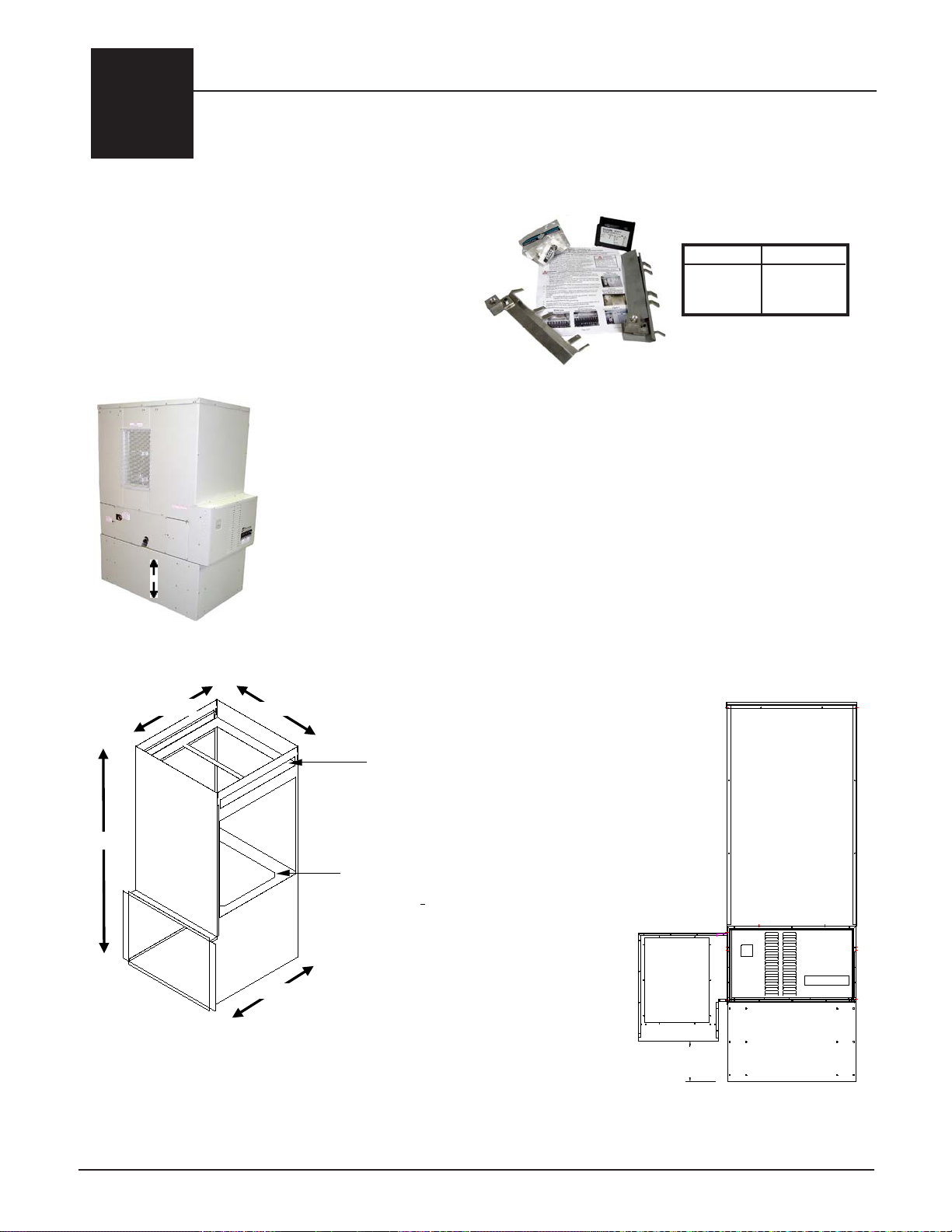
SINGLE ELECTRICAL FEED KIT
connectedtomultiplelinevoltagecircuits.Ifsinglefeed
to the element and blowers/control circuits is desired,
the single feed kit is available to allow the system to be
powered with a one, larger line voltage circuit.
COMFORT PLUS STAND
Someapplications(suchasgarages)may requirethattheheatingappliancebeelevated
RETURN AIR PLENUM
DOWN FLOW KITOrder Item #1301578
Order Item #1301550
Order Item #1301585
MODEL PART #
9.263
+ Set Height
of Leveling Legs.
Duct
Opening
(connects
to unit)
Filter Tray
(Fits 20" x 25" x 2" filters, one included)
Heating/Cooling A-Coil Tray
Inner Dimensions: 26"W x 22"D x 31" H
Front Access: 251
2"W x 22"D x 30"H
52 5/16”
28 3/16”
22 3/16”
26 1/16”
Optional Accessories
A factory built return air plenum is available for the 4100 series
systems and is ordered as a separate accessory. This plenum in-
corporates a tray for placement of a heating/cooling coil which
must get set in the return ductwork when interfaced to a heat
pump. The return air plenum connects directly to the 4100 series
The 4100 Series forced air systems are designed
the supply air plenum in a manner that directs
the air downward.
1301572
1301570
4120
4130/4140

MODEL ELEMENTS
4120 8
4130 12
4140 16
Comfort Plus Installation 3.01
Installation
3
SHIPPING AND PACKAGING
The Comfort Plus system should always be transported in an upright position to avoid damage to internal
components and insulation materials. The information below describes the items shipped with each system.
CERAMIC BRICK
ELEMENT SCREW KIT
(shipped inside
the
electrical
compartment)
5
(shipped inside the
electrical compartment)
OUTDOOR TEMPERATURE SENSOR
2
3
1INFORMATION PACKAGE
(includes Owner's Manual and
Warranty Registration Card)
(adhered to outer side of shipping box)
(shipped in box above
electrical compartment)
HEATING ELEMENTS
SUPPLY AIR BLOWER ASSEMBLY
(Ordered and shipped separately)
6
MODEL FULL BRICK 1/2 BRICK
4120 105 6
4130 150 12
4140 198 12
Full Brick
(shipped separately and
packaged 2 bricks per
package)
Half Brick
(shipped with brick and
packaged in a white box
consisting of 6 half brick
and 1 full brick)
CAUTION Risk of sharp edges. Can cause personal injury. Use caution when
installing and/or servicing equipment.
4

FRONT VIEW
TOP VIEW
48"
2" MIN
CLEARANCE
(IN COLD AIR RETURN)
6" X 6" REGISTER
FILTER TRAY
0" REQUIRED
CLEARANCE
M
STEFFES
P
M
M
A
0" REQUIRED
CLEARANCE
6" MIN CLEARANCE
36" MIN CLEARANCE
3" MIN CLEARANCE
1A
Installation 3.02 Comfort Plus
FIGURE 1
CLEARANCES
FRONT VIEW
TOP VIEW
48"
2" MIN
CLEARANCE
(IN COLD AIR RETURN)
6" X 6" REGISTER
FILTER TRAY
0" REQUIRED
CLEARANCE
M
STEFFES
P
M
M
A
0" REQUIRED
CLEARANCE
6" MIN CLEARANCE
36" MIN CLEARANCE
3" MIN CLEARANCE
1B
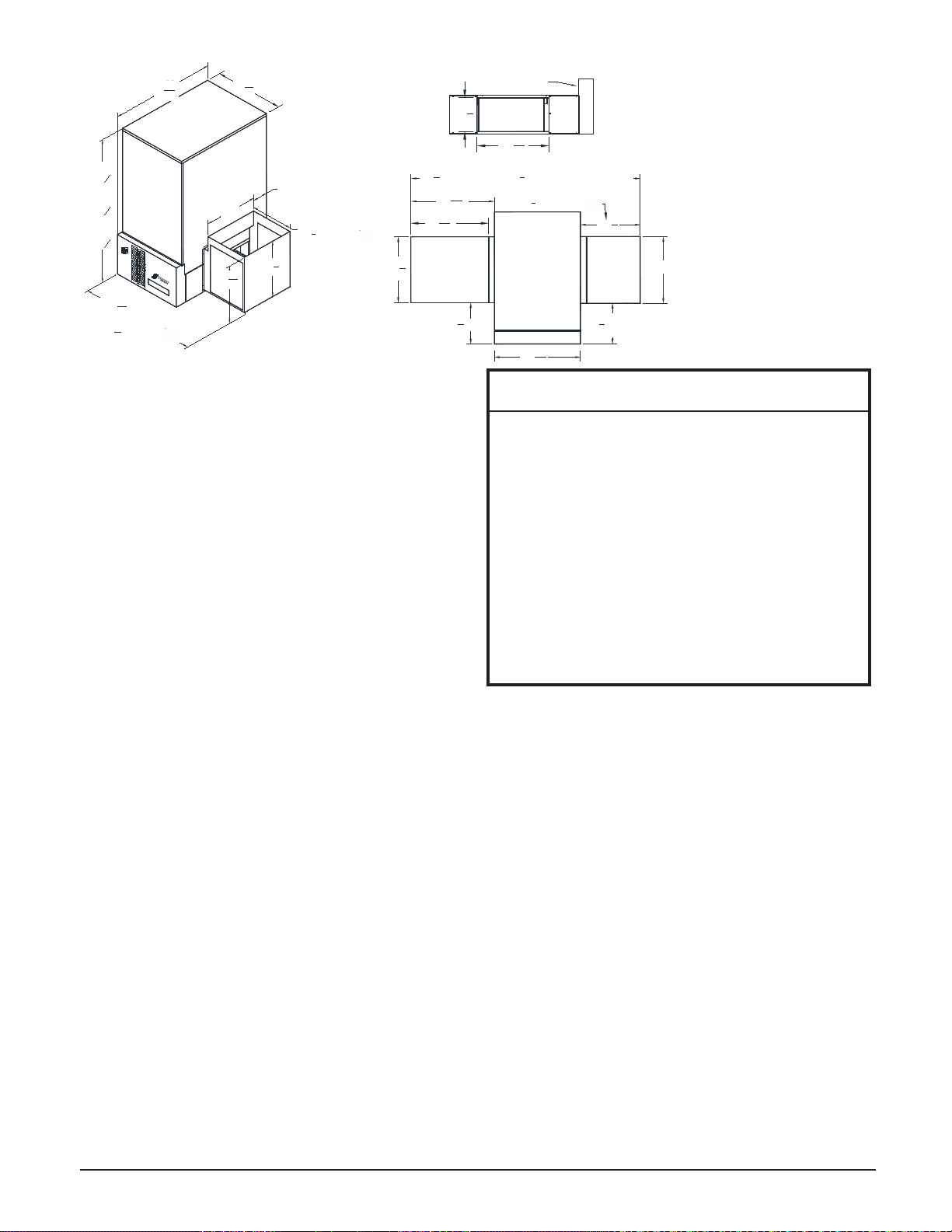
PLACEMENT AND CLEARANCE REQUIREMENTS
The physical dimensions of the Comfort Plus, along with the
clearances required, MUST be taken into consideration when
choosing its location within a structure. (See Figures 1 and 2 for
clearance requirements and system dimensions.)
The best installation location for this system is in a space
requiring heat so some amount of the heating requirements can
In situations where the Comfort Plus is not installed in an area it
is intended to heat (i.e. storage closet), it is important to account
for the heat lost through static dissipation by making proper
adjustments when sizing the system. Standby heat dissipation of
up to 2.5kW can be experienced in normal operation. Room air
should be maintained at less than 85° F/ 29° C.
If ventilation is needed, it can be provided by installing a 24” x
24” opening into the area where the Comfort Plus is located. In
addition, a 6” x 6” non-closing type register can be cut into the
return air duct of the furnace to minimize heat build-up in the
room. This register must be installed in a manner that ensures the
Figure 1A).
In addition to the physical space requirements, the weight of the
Comfort Plus must be taken into consideration when selecting the
Risk of re. Can cause injury or death.
• Violation of the clearance
requirements and/or failure to
provide proper ventilation can cause
improper operation of the system.
Maintain the placement and clearance
requirements as specied and provide
ventilation as necessary.
• Failure to maintain room temperature
in the mechanical room of 85o F/
29oC or less may result in equipment
damage. Thermostatically controlled
ventilation should be provided if the
temperature in this area exceeds 85o
F/ 29oC.
• Moving the system after install may
result in equipment damage. Do NOT
move system from original installed
location.
WARNING
Back and Sides = 3 inches (from combus-
tible material)
Bottom = 0 clearance
Top = 6 inches (from combustible material)
Front = 36 inches (for ease in servicing)
Between Duct and Left Side of System =
2 inches
Between Duct and Right Side of System =
0 clearance
Outer Sides of System Ducts (Return and
Supply) = 0 clearance
Minimum clearance requirements may NOT account for required working space for
electrical connections.
NOTE: Special requirements must be considered if placing the system in a garage or other area where combustible
vapors may be present. Consult local, state, and national codes and regulations to ensure proper installation.
An 18" pedestal (Order Item #1301585) is available to elevate the system.
NOTE:
24 3
4" if 3/4 or 1hp
133
4± 1/4"
14±1/4 4100 Series
Top View
263
16"
775
8" Standard - 82 1
8" if 3/4 or 1hp Supply
283
16"
201
4
293
16
Return Air Plenum
(Order Item
#1041570)
221
4"22 5/8"
Supply Air Plenum
(Factory Supplied)
4140
68
58
"
4130
57
58
"
4120
46
58
"
25 1
16"241
4"
4411
16"
8 3/8"
(± 1/4")
22 5/8"
M
A
M
STEFFES
P
M
(4100 Series)
18" Standard
22
1
2
" if 3/4 or 1hp
Front View
497
16" Standard
53
15
16
" if 3/4 or 1hp
293
16
Comfort Plus Installation 3.03
INITIAL SET-UP
Step 1 Remove the Information Package from the
outside of the shipping box and unpackage the
Comfort Plus heating system.
Step 2 Remove the heating elements from the box
above the electrical compartment.
Step 3 Move the system into its installation location.
30" doorway (minimum) without disassembling.
If necessary, the system can be disassembled
for ease in moving. Refer to the disassembly
instructions (Page A.02) for more information.
Step 4 Once in place, adjust the leveling legs on the
bottom of the system as necessary to prevent
rocking. If not placed properly the system
may bend or twist during the brick loading process, making element and brick core temperature sensor
Step 5 Remove the painted front panel of the electrical compartment by removing the screws along the edges.
Locate the element screw kit and the outdoor sensor.
Step 6 Remove the painted front panel of the brick storage cabinet by removing the sheet metal screws along the
top, bottom, and sides of the panel. Detach by pulling the bottom of the panel forward and down.
Step 7 Locate the element wiring harnesses behind the front painted panel. Carefully position them to avoid
damage during the brick loading and wiring processes.
Step 8 Locate the brick core temperature sensor(s) behind the front panel and disconnect them from their
shipping position. Carefully position the sensor(s) to avoid damage during brick loading and wiring.
Models 4130 and 4140 have two brick core temperature sensors.
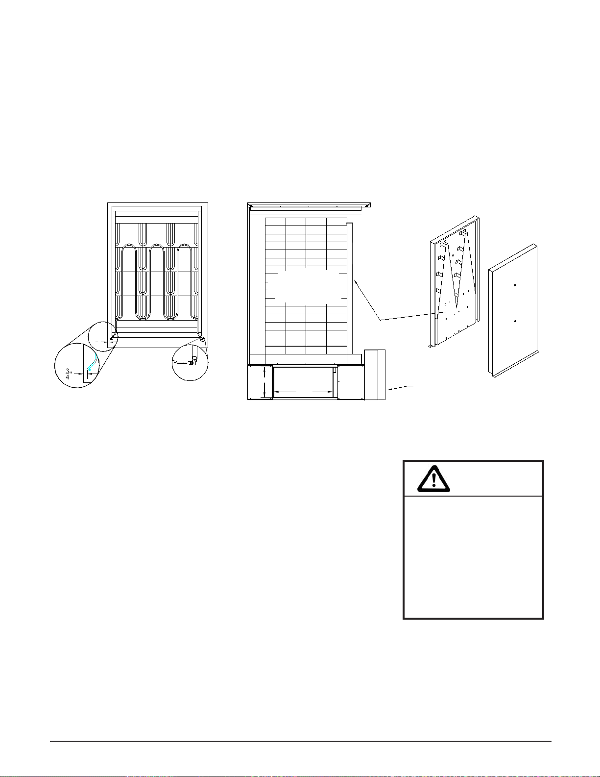
Step 9 Remove the galvanized front panel and set it aside.
Step 10 Starting at the bottom, carefully lift the two insulation blankets, one at a time, and drape them over the
top of the system.
Use face mask, gloves, and long sleeved garments when handling insulation materials in
compliance with generally accepted safety practices.
Step 11 Remove the front air channel by pulling out on the top of the air channel.
IMPORTANT
Risk of improper operation or equipment dam-
age. Read and follow installation instructions
carefully.
• Remove the Comfort Plus system from its
shipping pallet before installing.
• Leveling legs should be extended no more
than one inch.
• DO use and follow generally accepted safety
practices when handling insulation material.
• DO have equipment installed by a qualied
technician in compliance with all applicable
codes and regulations.
FIGURE 2
DIMENSIONS Return air duct MUST
NOT enter from the
front or back of the
furnace. Upow,
downow, or straight
return ducting only.
2B
2A 101
2
225
16
Electrical
Panel
47 "
5
16
161
2161
4
NOTE:
NOTE:
NOTE:
HP
HP
HP
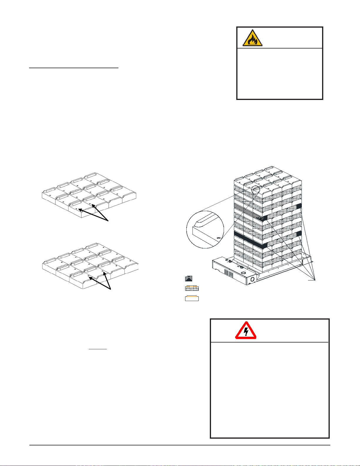
4120 - Load in Row 5
4130 - Load in Row 4 and 8
4140 - Load in Row 6 and 12
Half Brick
Forward Facing Indicator
Rear Facing Indicator
Half Brick
Indicator in Brick
HEATING ELEMENT AND AIR CHANNEL INSTALLATION
Step 1 After all brick are loaded, insert the heating elements
between the brick layers, sliding them in until the element
ends embed into the side cutouts of the brick cavity.
The elements MUST be installed so their threaded screw
tabs on the wire connection terminals point forward and
down. If they are installed with the screw tabs pointing
upward, element-to-wiring harness connections (Figure
brick core properly to ensure correct clearance between the
terminal connections and any surfaces within the system as
shown in Figure 6.
Step 2
shaped pieces) facing inward and with the narrow ends of
Installation 3.04 Comfort Plus
BRICK LOADING
Load the brick, one row at a time, using a left side, right side, center pattern.
Start at the back of the brick core and work forward. Make sure the brick are
placed so the grooved side is facing up and the ridges are on the left and right.
(See Figure 5.)
BRICK INSTALLATION TIPS:
•Install bricks carefully to avoid damage to the insulation panels.
•Remove loose brick debris to prevent uneven stacking of brick, as this
can make installation of the elements and the brick core temperature
•Brick rows MUST line up front to back and side to side.
•Half brick makes brick loading easier by evening out the stacks. Use HALF BRICK (white boxes) in the
proper rows and positions as indicated in Figure 5.
•
•All bricks in odd numbered rows (1, 3, 5, 7, 9, and 11) must have the indicator facing forward as shown in
Figure 3.
•All bricks in even numbered rows will have indicator facing back. See Figure 4.
Risk of re. Can cause
personal injury or death.
DO NOT operate the system
if damage to the insulation
panels on the inner sides of
the brick core occurs.
WARNING
HAZARDOUS VOLTAGE: Risk of
electric shock. Can cause injury or
death.
• DO NOT remove the electrical panel
cover while system is energized.
• Position elements properly to avoid
short circuiting them against metal
surfaces.
• Protect element lead wires from
front panel screws and any eld
installed screws to avoid short
circuit.
WARNING
FIGURE 5
FIGURE 3
i.e.: Rows 1, 3, 5, 7, 9, and 11 in 4140
Front
Indicator
FIGURE 4
i.e.: Rows 2, 4, 6, 8, 10 and 12 in 4140
Front
Indicator
3
4"
Required Clearance Between
Element Termination and Metal
Panels is 1/2" (3/4" Nominal)
Element Connection
Comfort Plus Installation 3.05
Step 3 Lower the insulation blankets back into position, one at a time. Carefully tuck the sides of the insulation
into the edges, corners, and around the exposed portions of the heating elements to ensure maximum
Step 4 Reinstall the galvanized front panel and secure it to the Comfort Plus system using the screws that were
originally removed. Slide the bottom of this panel inside the lower lip of the brick cavity. The top rests on
the outside of the cavity.
Step 5 Carefully route wiring harnesses and connect them to the heating elements, using screws provided in the
hardware package. Make connections with screw heads up and threads pointing down. Element screws
should be tightened to 30 inch lbs. Refer to Element Connection (Figure 6) for proper positioning.
ELEMENT INSTALLATION
FIGURE 6
TOP VIEW
AIR CHANNEL PLACEMENT
FIGURE 7
BRICK CORE TEMPERATURE SENSOR INSTALLATION
Step 1 Remove the screw(s) by the brick core temperature sensor hole(s) in
the galvanized front panel.
Models 4130 and 4140 have an upper and a lower brick core
temperature sensor.
Step 2 Insert the brick core temperature sensor(s) through the hole(s) in the
galvanized front panel. If installing a system with two sensors, be sure
the one marked "upper" is installed in the upper opening and the one
marked "lower" is installed in the lower opening. The sensor(s) must
pass through the blanket insulation and into the brick core. Holes have
not been predrilled through the insulation. Use the sensor(s) to aid
in making a passageway by rotating the sensor(s) side-to-side while
gently pushing inward.
Step 3 Once the brick core sensor(s) is installed, put the screw(s) back into position in the galvanized front panel
to hold the sensor(s) in position and to provide the electrical ground.
Step 4 Check the non-insulated element terminations to make sure they do not come within 1/2" of any surface
area on the system.
Step 5 Re-install painted front panel, using previously removed screws.
Risk of improper
operation. Proper
installation of the brick core
temperature sensor(s) is
critical to the operation of
the Comfort Plus heating
system. Read and follow
installation instructions
carefully.
CAUTION
20.3"
10.4"
BRICK
CORE
SIDE VIEW
Front Air Channel
Electrical
Panel
Brick Side Bottom
Back View
Front View
NOTE:
DUCTING & AIR FLOW
For air delivery, the Comfort Plus is equipped with a
variable speed supply air blower. When interfacing
with a heat pump, the A-Coil MUST be placed on the
return air side.
To maintain a room temperature of 85o F/ 29oC or less
in the mechanical room, a 24" x 24" opening can be
installed in the area or a 6" x 6" non-closing register
can be cut into the return air duct. Refer to Placement
and Clearance Requirements (Page 3.02) for more
information.
holes directly above the air outlet on the right side
of the 4100 Series MUST be contained in the duct
system. (See Figure 8 for reference to these air holes.)
must be ordered from the factory (Order Item #1301578)
the ground. An 18" pedestal is available (Order Item
#1301585) to elevate the Comfort Plus.
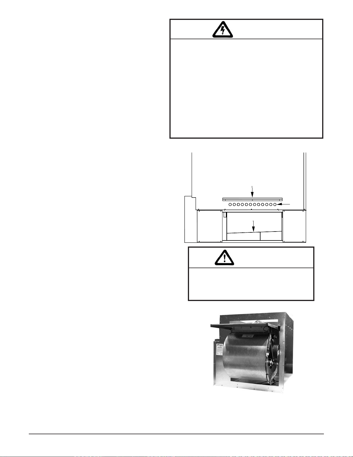
Step 1 Unbox the supply air blower plenum assembly.
Step 2 Remove and discard metal plate securing
supply air blower to plenum assembly.
Step 3 Locate the plenum support bracket shipped
in the plenum box. Attach the bracket to the
supply air side using the blunt tip screws
supplied in the plenum assembly hardware
package. Refer to Figure 8 for proper
positioning of the plenum support bracket.
Step 4 Attach the supply blower wiring harness
located in the base of the system to the blower.
Be sure to place any excess wiring in the base
of the system below the radiant heat shield
(Figure 8).
Step 5 Verify that the blower is installed in the plenum with the
motor facing away from the system (Figure 9).
Step 6 Attach the supply air blower plenum to the Comfort Plus by
drilling two 1/8” holes per edge and using the self tapping
screws supplied in the hardware package.
Step 7 Connect both the return air and supply air ducting systems
in the structure to the Comfort Plus system. Be sure the air
holes just above the air outlet on the right side are contained
in the duct system. (See Figure 8 for reference to the
location of these holes.)
Installation 3.06 Comfort Plus
HAZARDOUS VOLTAGE:
Risk of electric shock. Can cause injury or death.
• Do install ducting before energizing the system.
• Do NOT operate the Comfort Plus without ducting
installed to both the air inlet and outlet.
• Proper duct design and air ow are critical to
achieve optimum system performance. A poorly
designed duct system and/or improper air ow can
cause system ineciencies, air noise, and conden-
sate drain problems. In applications where poor
air ow conditions exist along with high humidity,
it may be necessary to install a secondary conden-
sate drain pan.
WARNING
FIGURE 9
SUPPLY AIR PLENUM ATTACHMENT
FIGURE 8
When routing the harness to the supply air
blower, the harness must route to the side of
the air deector in the bottom of the supply
air blower housing.
CAUTION
Air
Holes
Plenum Support Bracket
Radiant Heat Shield
Comfort Plus Installation 3.07
FIGURE 10
External static pressure should not exceed .75 inches water column.
NOTE: With 2 stage Heat Pump, a Stage 1 heat call results in 70% of
selected CFM.
Step 8 Connect the supply air duct in the
structure directly to the system's air
outlet located on the top panel.
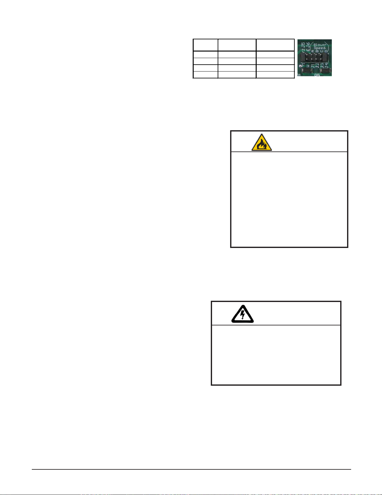
Step 9 Adjust the CFM setting at the
variable speed low voltage circuit
board as shown in Figure 10.
Step 10 The W/E jumper (Figure 10) MUST
be in the ON position or the blower
will not operate with an E call from
the thermostat.
Jumper
½ HP Variable
Speed CFM
1 HP Variable
Speed CFM
A
1000
1200
B
1200
1400
C
1400
1600
D
1600
2000
AIR CONDITIONER/HEAT PUMP INTERFACE
When interfacing the Comfort Plus system with a heat pump, the
indoor coil MUST be placed on the return side of the Comfort Plus
access cover and slide the coil into place inside the plenum. If not
When interfacing a Comfort Plus system with an air conditioner, the
indoor coil can be placed on either the supply air or the return air side
of the system.
The condensate drain trap, in a heat pump or air conditioner
installation, should be designed for the vacuum in which the system
is operating. Typically, taller traps are better suited for these types of
applications.
Refer to the Room Thermostat Connections Diagrams (Figures 14, 15 and 16) for more information on interfacing
the Comfort Plus with a heat pump or air conditioner.
WARNING
Risk of re. Any one ducting system
MUST NOT contain more than one
air handling (blower) system. If the
application requires multiple Com-
fort Plus systems or it is necessary to
have multiple air handlers share the
same ductwork, you MUST contact
Stees. There are special installation
requirements that MUST be per-
formed in an application such as this.
LINE VOLTAGE ELECTRICAL CONNECTIONS
connection to 240V, however, the element circuits can also be
connected to 208V. A 208V connection derates the charging
208V or 277V is required, contact the factory. The controls
circuit in the Comfort Plus system MUST be connected to
240V/208V.
The 60 amp breakers located in the electrical compartment on
the Comfort Plus feed the core charging (element) circuits. The
15 amp breaker feeds the controls and blowers circuit.
HAZARDOUS VOLTAGE: Risk of
electric shock. Can cause injury or
death. Do not energize the system until
installation is complete. Equipment MUST
be installed by a qualied technician in
compliance with all applicable local, state,
and national codes and regulations.
WARNING
All Comfort Plus systems are factory congured to be eld connected to multiple line voltage circuits.
If a single feed line voltage circuit is desired, an optional single feed kit is available.
NOTE:
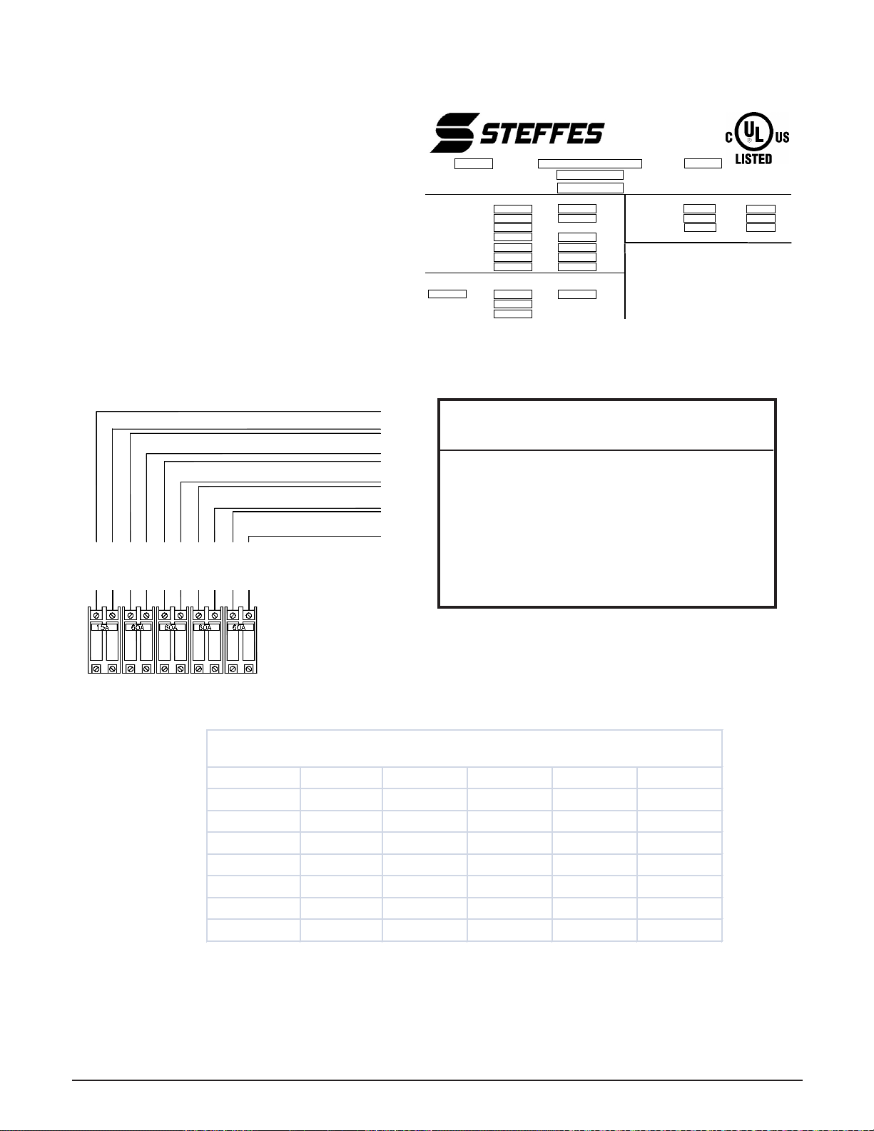
To determine the correct wire size required for
each circuit feeding the Comfort Plus, refer to
the system. (Reference Sample Label Figure 11.)
Step 1 Remove the electrical panel cover.
Step 2 Route all line voltage wires through a
knockout and into the electrical panel of the
Comfort Plus.
Step 3
the Comfort Plus breakers. Refer to the
Line Voltage Wiring Diagrams (Pages
A.06 - A.08) for more information on these
connections.
CIRCUIT PHASING CONNECTIONS
FIGURE12
Installation 3.08 Comfort Plus
The 60 AMP breakers on the Comfort Plus are for internal component protection only. Sizing of
the eld wire and overcurrent protection MUST be in compliance with all applicable local, state,
and national codes and regulations.
• To ensure proper operation and safety, all line
voltage circuits must be segregated from low
voltage wiring in the Comfort Plus.
• To reduce electro magnetic elds associated
with electrical circuits and to avoid induced
voltage on sensors and electronic devices, the
circuit phases MUST be alternated as shown
in Figure 12.
IMPORTANT
Model Control Crct Chrg Crct #1 Chrg Crct #2 Chrg Crct #3 Chrg Crct #4
4120 - 14.0kW 7.00 21.88 21.88 14.58 N/A
4120 - 19.2kW 7.00 30.00 30.00 20.00 N/A
4120 - 24.8kW 7.00 38.75 38.75 25.83 N/A
4130 - 28.8kW 7.00 30.00 30.00 30.00 30.00
4130 - 37.2kW 7.00 38.75 38.75 38.75 38.75
4140 - 38.4kW 7.00 40.00 40.00 40.00 40.00
4140 - 45.6kW 7.00 47.50 47.50 47.50 47.50
Full Load Current
(240VAC only - Circuit deration not included)
Circuit Breakers
LINE 2
LINE 1
LINE 2
LINE 1
CHARGE CIRCUIT #3
CHARGE CIRCUIT #2
CHARGE CIRCUIT #1
BLOWERS/CONTROLS CIRCUIT
CHARGE CIRCUIT #4
(MODEL 4130 and 4140 ONLY)
LINE 2
LINE 1
LINE 1
LINE 2
LINE 1
LINE 2
To Service (Breaker) Panel
(4100 SERIES ONLY)
SAMPLE SYSTEM IDENTIFICATION LABEL
FIGURE 11
Manufactured in U.S.A.
Electric Central
Heating Furnace
5P99
Model
S/N
Option .
Maximum Discharge Air Temperature U.S. Patents – 5201024, 5086493
Maximum External Static Pressure inches H20Canadian Patents – 2059158, 2060881
Connections Required for Multi-Circuit Feed
Max Amps of Motors
Control Circuit Volts
Amps
Core Blower #1
Amps
HP
Min Circuit Ampacity
Amps
Hz
Core Blower #2
Amps
HP
Max Fuse Size Amps
House Blower Amps
HP
Charge Circuit #1 Volts
Watts
Charge Circuit #2 Volts
Watts
Clearance Requirements (4100 Series)
Charge Circuit #3 Volts
Watts
Allow three (3) inches from
back and sides, six (6)
inches from top of unit to combustables, and two
(2) inches from left side of unit to ducting. Allow
thirty-six (36) inches front clearance to provide
space for servicing. No clearances are required
from ducting, or to floor surfaces.
Charge Circuit #4 Volts
Watts
Connections Required for Single Circuit Feed
Short
-
circuit current: 5kA rms symmetrical, 240V
Volts
Amps
Hz
Min Circuit Ampacity
Amps
Max Fuse Size Amps
Label
12005
0
3
Rev 1
NOTE:

Comfort Plus Installation 3.09
PEAK CONTROL CONNECTIONS
Module, or line voltage wiring. In applications utilizing automatic charge
control, outdoor temperature information is required and can be received via
an outdoor sensor or power line carrier control system.
control and is set to charge when the utility peak
Menu (Pages 3.13-3.14) for information on
LOW VOLTAGE (DIRECT WIRED) PEAK
CONTROL
If using the low voltage peak control option, the
Comfort Plus is direct wired to the power company's
peak control switch. Field connections from the
peak control switch are made to the low voltage
terminal block through a low voltage knockout
located on the left side of electrical panel.
Step 1 Route a low voltage circuit from the
signaling device to the terminal block
inside the electrical compartment of the
Comfort Plus.
Step 2
To control other devices, refer to the Auxiliary Load Control on Page 3.12.
POWER LINE CARRIER (PLC) PEAK CONTROL
existing electrical circuits in the structure. With the power line carrier option, direct wired low voltage connections
from the power company's peak signaling switch connect directly to the transmitting device. The switch signals
peak control times to the transmitter, the transmitter sends the signals to the Comfort Plus system, which receives
this information and responds accordingly.
In addition to providing peak control signals, the transmitter also provides outdoor temperature information for
automatic charge control, room temperature set back, and anticipated peak utility control signals (if applicable).
The PLC system is optional and must be ordered separately. If utilizing a PLC system, an Owner's and Installer's
manual will accompany the transmitting device. Refer to this manual for information on the installation and
operation of the power line carrier control system.
TIME CLOCK MODULE PEAK CONTROL
optional time clock module mounts inside the line voltage electrical compartment and interfaces with the relay
board via an interface cable. Peak control times MUST be programmed into the system once the module is
installed to enable the time clock feature. Refer to the instructions provided with the time clock module for more
information on the installation and operation of this device.
Never install any wiring in
a line voltage compartment
of the Comfort Plus unless
it is rated for line voltage.
IMPORTANT
Terminal Block Coding
RP = Peak Control Input Common
P = Peak Control Input
AP = Anticipated Peak (Pre-Peak) Control Input
COM = Peak Control Output Common
NC = Peak Control Output (Normally Closed)
NO = Peak Control Output (Normally Open)
PEAK CONTROL
TERMINAL CONNECTIONS
FIGURE 13
NOTE:
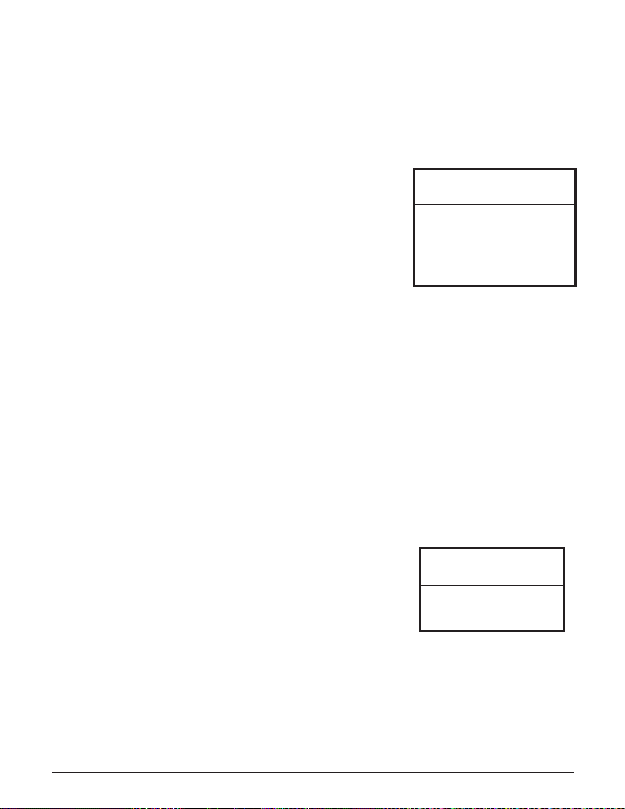
LOW VOLTAGE ELECTRICAL CONNECTIONS - ROOM
THERMOSTAT
A low voltage (24VAC) room thermostat is required for room temperature
thermostat. If utilizing a mechanical thermostat, a load resistor may be
necessary due to the low current draw (.01 amps) on the heat call input circuit
of the Comfort Plus system. Contact the factory for information on thermostats
Installation 3.10 Comfort Plus
LINE VOLTAGE PEAK CONTROL
Line voltage control is also an option, but is not the preferred method of control as it is usually more complex and
expensive. If line voltage control is utilized, the controls circuit must be powered with an uninterrupted circuit.
An external switching device, such as a relay panel, is necessary to directly control the heating element charging
circuits. If relying on this method of control, the display on the system must continuously display a brick core
LOW VOLTAGE ELECTRICAL CONNECTIONS - OUTDOOR
TEMPERATURE SENSOR (RECOMMENDED)
Installation Methods: A) Hard wired to system to the two "outdoor"
terminals (default)
OR
B) Connected to Power Line Carrier (PLC)
Theory of Operation: The outdoor sensor monitors outdoor temperature
and provides this information to the system. The
system responds by automatically storing heat in its
brick core according to outdoor temperature and the
heating requirements.
Location of: The outdoor sensor must be placed in a location where it can accurately sense outdoor temperature
Wiring: • Route low voltage wire from the outdoor sensor to the electrical compartment through one of the low
voltage wire knockouts.
• Connect to the two terminals labeled "outdoor".
• If the sensor wiring is routed through an external wall, the opening through which the wire is routed
• The outdoor sensor is supplied with a lead length of 40 ft. If a greater wire length is needed, it can be
extended to a total of 250 ft.
• No other loads can be controlled or supplied through this cable. It is for connection of the outdoor
sensor ONLY.
• This low voltage cable MUST not enter any line voltage enclosure.
• Unshielded Class II (thermostat) wire can be used as extension wire provided it is segregated from any
line voltage cabling.
If connecting to the
Stees power line carrier
(PLC) system, follow the
installation instructions in the
PLC system's Owner's and
Installer's Guide.
IMPORTANT
Low voltage wires MUST
never enter any line voltage
enclosure.
IMPORTANT

P8
Peak Aux.
Inputs Relay
The Y1/Y2 Jumper must be installed
Honeywell TH5220D
Aux
EL CG O/B RY R
c
C - Low Voltage Common
R - Low Voltage Hot
O - Reversing Valve
Y - Compressor
To Heat Pump
Outdoor Sensor
The W/E Jumper must be installed
P9
H/E
R C
Outdoor
Outdoor
COM
NC
NO
W/
D6
RLY1
To Control Board
D4
Fid 2
Blower
To Control Board
Air
C3
P10
R1
R2
P11 D5 D7 D3
Water
Y1 Y2
W E
D2
J3
J2
J1
P5
D1
J4
P6
P4
Speed
Blower
J6
J5
C
B
A
D
P2P3
Y1
AUX OGY2 Y1 2
Y2
2 2 O
C
R
Comfort Plus
LV Circuit Board
P7
APPRP
P1
The W/E Jumper must be installed
Air
To Control Board
D4
Fid 2
Blower
C3
R1
R2 P10
D6
RLY1
P11 D5 D7 D3
Water
W E
Y1 Y2
P5
J3
J2
J1
D2
J4
D1
P6
P4
C
B
A
D
Speed
Blower
J6
J5
P3 P2
P8 P9
Air Conditioner
Connections
(If being used in the
application)
The Y1/Y2 Jumper must be installed
Y
W
G
C
TH5110D
Honeywell R
c
R
Y
Outdoor
W/ Y1
AUX G OY2 Y1
R C
H/E 2O22 Y2
COM
Outdoor
NO
APPRP
NC
Aux.Peak
Inputs Relay
C
P1
To Control Board
Comfort Plus R C
LV Circuit Board
P7
Comfort Plus Installation 3.11
STAND ALONE FURNACE APPLICATION WITH VARIABLE SPEED BLOWER
CONNECTIONS SHOWN FOR SINGLE STAGE HEATING / SINGLE STAGE
COOLING (UNCONTROLLED AIR CONDITIONING)
FIGURE 14
SINGLE STAGE HEAT PUMP APPLICATION WITH VARIABLE SPEED BLOWER
FIGURE 15
IMPORTANT
If installing a mechanical thermostat or thermostat with anticipator, a resistor kit is required (Order
Item #1190015).
IMPORTANT
*If multiple inputs are active, system
will display highest Heat Call values.
** Thermostat must be programmed to
energize reversing valve for cooling.
If outdoor unit used requires the
reversing valve be energized for
heating, see Conguration Menu on
pages 3.13-3.14.
Thermostat
Stage
Thermostat
Output
Heat
Pump
Stage
% of
Selected
CFM
Heat Call Status
on Digital
Display*
Discharge Air
Temperature
Target
1Y1/G 1100% HC1 L048
2Aux/Y1/G 1100% HC2 L049
Fan G 0 400 cfm HCF N/A
Cool Y1/G/O 1100% COOL N/A
Emergency H/E 0100% HC3 L049
SINGLE STAGE HEAT PUMP
Contractor Use Only
**
NOTE:
1
Honeywell TH5320U
RRYCO/BG
Aux
Y2
Y2 - Compressor Stage 2
C - Low Voltage Common
c
L
R - Low Voltage Hot
O - Reversing Valve
To Heat Pump
Y1 - Compressor Stage 1
The Y1/Y2 Jumper must be removed
W/
NO
NC
COM
Outdoor
Outdoor
CR
H/E
RLY1 D6
To Control Board
Fid 2 D4
Blower To Control Board
O
D3
R2
R1
D7D5
P11
W E
Y1 Y2
Water
J4
D1
P5
J1
J2
J3
P10
P6
D2
D
A
B
C
C3
J5
J6
Blower
Speed
P4 P3
AUX Y2 G
Y1 O
22
Y2Y1
R
Air
LV Circuit Board
Comfort Plus
P7
P1
P2
P8
C
P9
RP
2
APP
Aux.
Relay
Peak
Inputs
The W/E Jumper must be installed
Installation 3.12 Comfort Plus
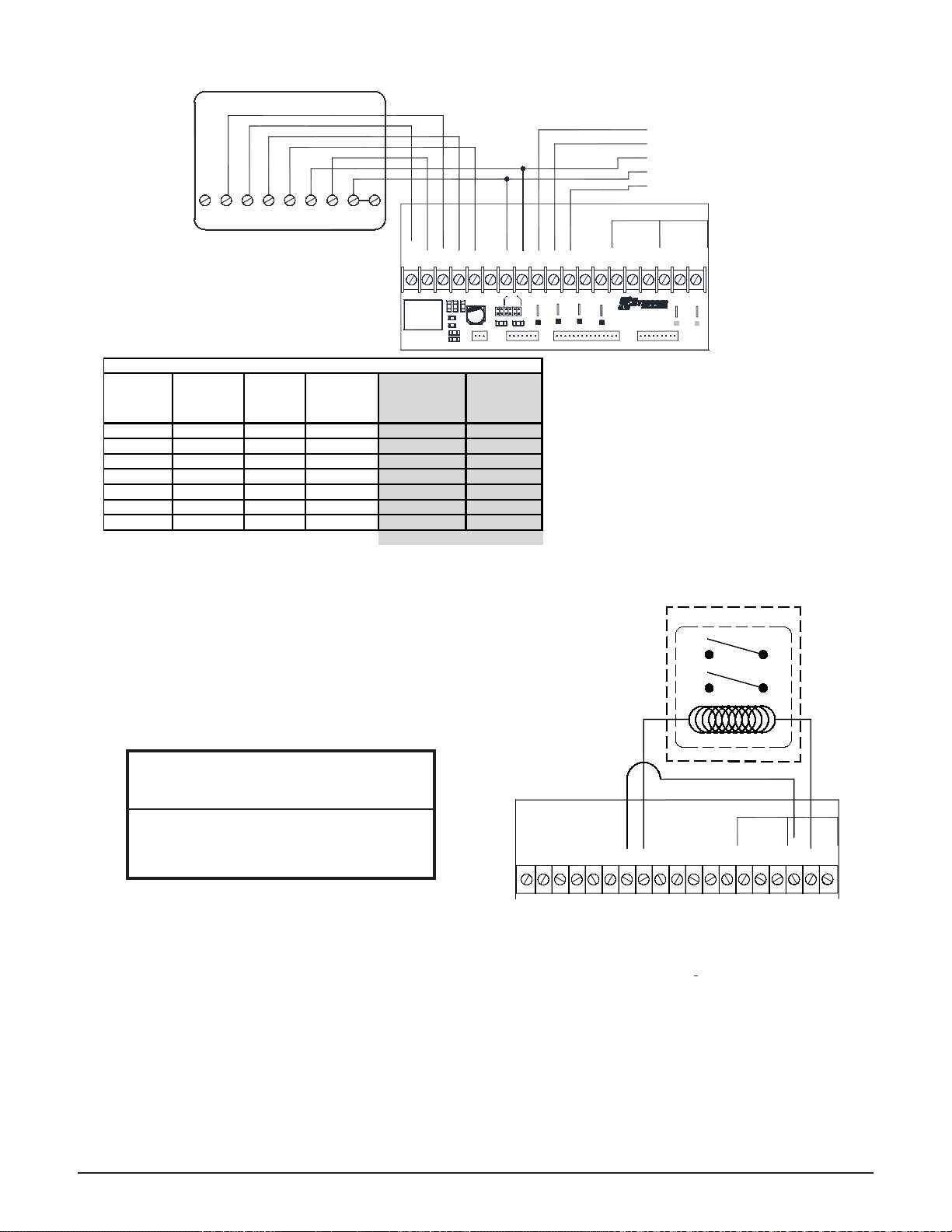
AUXILIARY LOAD CONTROL
The Comfort Plus can be used to provide control signals
to other loads in the application. To do so, connect low
voltage control wires to the "COM" and "NC" or the
"COM" and "NO" positions of the low voltage terminal
block in the electrical compartment of the Comfort Plus
system. (See Figure 17.) These contacts are rated for 30
volts, 3 amps maximum.
HUMIDIFIER/ELECTRONIC FILTER INSTALLATION
of these devices, connections to the Comfort Plus system are made to the bottom two relays on the base I/O relay
board inside the system's electrical panel. Refer to the Line Voltage Wiring Diagrams (Page A.06-A.08) for the
location of these relays.
during a heat call.
Maximum external load should not
exceed 60 VA on the system's class II
transformer.
IMPORTANT
TWO STAGE HEAT PUMP APPLICATION WITH VARIABLE SPEED BLOWER
FIGURE 16
TYPICAL AUXILIARY LOAD CONTROL
FIGURE 17
NOTE: During o-peak (charge) periods, the contact is
closed between "COM" and "NC".
IMPORTANT
* If multiple inputs are active, system will dis-
play highest Heat Call values.
** Systems built before 1/1/2011 are congured
for 50% airow in Stage 1. For more infor-
mation, refer to Instruction #1200601-High
Speed Stage 1 Relay Installation.
*** Thermostat must be programmed to energize
reversing valve for cooling. If outdoor unit
used requires the reversing valve be ener-
gized for heating, see Conguration Menu
on pages 3.13-3.14.
Thermostat
Stage
Thermostat
Output
Heat
Pump
Stage
% of
Selected
CFM
Heat Call
Status on
Digital Display*
Discharge Air
Temperature
Target
1Y1/G 150% or 70%** HC1 L048
2Y1/Y2/G 2100% HC1 L048
3Aux/Y1/Y2/G 2100% HC2 L049
Fan G 0 400 cfm HCF N/A
Cool 1 Y1/G/O 150% or 70%** COOL N/A
Cool 2 Y1/Y2/G/O 2100% COOL N/A
Emergency H/E 0100% HC3 L049
Contractor Use Only
TWO STAGE HEAT PUMP
***
W/
NO
NC
COM
Outdoor
Outdoor
CR
H/E
A
Blower
Air Water
C
D
B
To Control Board CR
Speed
Blower
Y1-Y2 W-E
Y2Y1
AUX OG RP
22
Y1 Y2
2
OAPP
Inputs
Peak Aux.
Relay
Auxiliary Control Relay
Relay Contacts
Relay Coil
COM
NO/NC
COM
NO/NC
This manual suits for next models
2
Table of contents
Other Steffes Heater manuals


Popular Heater manuals by other brands


Webasto
Webasto Thermo Call TC2 COMFORT installation manual

FAFCO
FAFCO SUPER solar beat Installation and owner's manual

Burda
Burda NOGLARE NRCAC065 Assembly and operating instructions

Hyco
Hyco AN1000 Product instruction manual

Webasto
Webasto Dual Top ST 6 Workshop manual

Orbegozo
Orbegozo RAW Series instruction manual

Jaga
Jaga DBH 10 manual

Panasonic
Panasonic PHK-12 installation instructions

Chromalox
Chromalox STAR-02A-11-PC Installation, operation and renewal parts identification

Master
Master MH-60VBOA-GFA User's manual & operating instructions

Sawotec
Sawotec KRIOS manual

Parkside
Parkside PKH 2000 B1 Operation and safety notes