Steffes Comfort Plus Hydronic 5120 User manual

12
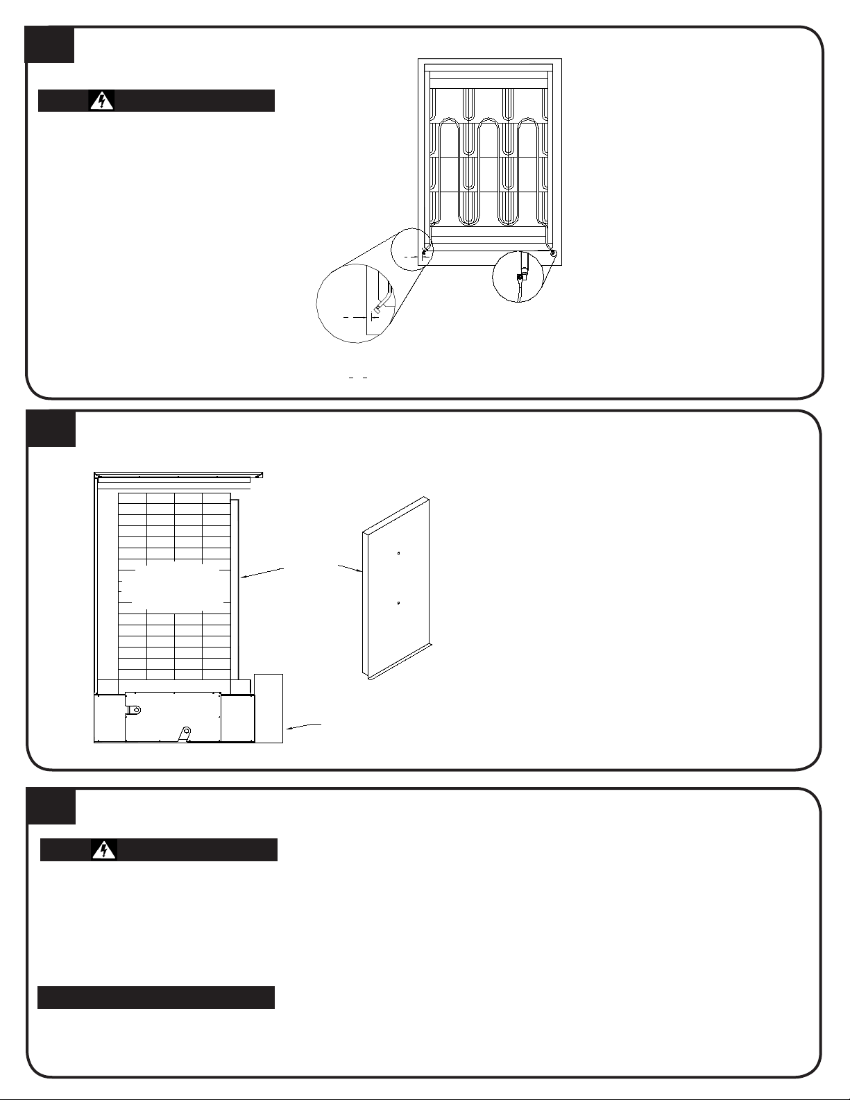
PLACEMENT AND CLEARANCES SET-UP
Minimum Clearance Requirements
A Back and Right Side = 3 inches from
combustibles
B Front = 36 inches
C Top = 6 inches from combustibles
D Bottom = 1 inch from combustibles
E Left Side = 36 inches
Quick Reference Installation Guide
3BRICK LOADING
1. Place system in desired location.
2. Adjust leveling legs.
3. Remove painted front panel of brick
storage cabinet.
4. Position element wiring harnesses
to avoid damage during brick
loading.
5. Position brick core temperature
sensor(s) to avoid damage during
brick loading.
6. Remove galvanized front panel.
7. Starting at bottom, lift and drape
insulation blankets over top of
system.
8. Remove front air channel by pulling
out at top.
9. Remove heating elements from
inside brick core cavity.
• DO NOT extend leveling legs
more than one inch.
• DO use and follow generally
accepted safety practices when
handling insulation material.
• Equipment MUST be installed
by a qualied technician in
accordance with all applicable
local, state and national codes
and regulations.
• Reference Owner’s and Installer’s
Manual for complete safety,
installation, and operation
instructions.
Starting at the back of the brick core cavity,
load bricks one row at a time using left side,
right side, center pattern. Place bricks with
grooved side facing up, notch facing forward,
and ridges on left and right.
If area available to install Comfort
Plus Hydronic system is less than
100 square feet, consult factory. If
installing in area with less than 400
square feet, ventilation MUST be
provided. Temperature in area should
be maintained at or below 85oF/29oC.
“Manufactured in North America”
COMFORT PLUS
HYDRONIC
Models 5120, 5130, 5140
CAUTION
WARNING
Front of Unit
Notch in Brick
HALF BRICK
5120: Load in row 5
5130: Load in row 4 and 8
5140: Load in row 6 and 12
IMPORTANT
A
TOP VIEW
E
E
D
A
C
FRONT VIEW
A
B
M
A
M
M
P
A
TOP VIEW
E
E
D
A
C
FRONT VIEW
A
B
M
A
M
M
P
• Remove loose
debris from brick.
• Brick rows MUST line
up front to back
and side to side.
• Use half bricks in proper rows and in
correct positions. The notch in the
brick MUST be toward the front of
the furnace.
4HEATING ELEMENT INSTALLATION
1. Insert heating elements
between brick layers until
element ends embed into
side cutouts of brick cavity.
Elements MUST be installed
with threaded screw tabs on
wire connection terminals
pointing forward and down.
2. Remove painted panel from
electrical compartment
and locate the installation
hardware package.
3. Connect wiring harnesses
to heating elements using
screws in hardware package.
Install screws with heads
up and thread pointing
down. Tighten screws to
approximately 30 in·lbs.
5AIR CHANNEL INSTALLATION
1. Install air channel with air deectors (arrow
shaped pieces) facing inward. Place bottom of air
channel in rst.
2. Lower insulation blankets back into position,
one at a time. Tuck sides into edges, corners and
around exposed portions of heating elements.
3. Install galvanized front panel. Slide bottom edge
inside lower lip of brick cavity. Top rests on
outside of cavity.
4. Check non-insulated element connections to make
sure they do not come within 1/2” of any surface.
6BRICK CORE TEMPERATURE SENSOR(S) INSTALLATION
1. Remove screw(s) by temperature sensor hole(s) in galvanized
front panel.
2. Insert temperature sensor(s) through hole(s). Sensor(s) must
pass through blanket insulation and into brick core.
3. Install screw(s) into galvanized front panel to hold sensor(s)
and provide electrical ground connection.
4. Inspect sensor wiring for possible short circuiting hazards.
5. Install painted front panel.
WARNING
HAZARDOUS VOLTAGE: Risk of
electric shock, injury or death.
• DO NOT remove electrical panel
cover while system is energized.
• Elements MUST be positioned
properly to avoid short
circuiting them against any
surfaces within system.
• Use care when making
connections to avoid element
damage.
3
4"
3
4"
Required Clearance
Between Element Termination and
Metal Panels is 1
2" (3
4" Nominal).
Element
Connection
BRICK
CORE
SIDE VIEW
Outlet
Inlet
Electrical
Panel
Front Air
Channel
WARNING
Risk of improper operation.
Proper installation of the brick
core temperature sensor(s) is
critical to the operation of the
Comfort Plus Hydronic system.
Read and follow installation
instructions carefully.
IMPORTANT
Models 5130 and 5140 have an upper
and a lower temperature sensor. Each
sensor is marked for proper installation.

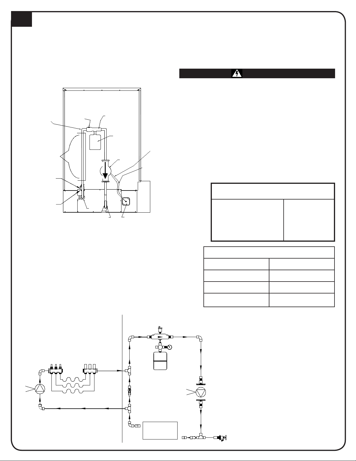
7LINE VOLTAGE
ELECTRICAL CONNECTIONS
• To ensure proper operation and safety, all line voltage circuits must be
segregated from low voltage wiring.
• To reduce electromagnetic elds associated with electrical circuits
and to avoid induced voltage on sensors and electronic devices, the
circuit phases MUST be alternated as shown below.
• DO NOT install any wiring in the line voltage compartment of the
Comfort Plus Hydronic system unless it is rated for line voltage.
CIRCUIT PHASING CONNECTIONS
9JUNCTION BOX INSTALLATION
1. Attach the factory supplied junction
box to the left side of the Comfort
Plus Hydronic system.
2. Make connections to the primary loop
pump and air handler pump inside
this junction box. The red and white
wires connect to the primary loop
pump and the black and white wires
connect to the air handler pump. The
maximum connected amperage on
either of these circuits is 1.2 amps.
3 . Attach the junction box cover using
the screws provided.
If NOT utilizing the optional Static Heat Recovery Unit, the orange wire can be used to power a secondary pump.
8AIR CONDITIONER/
HEAT PUMP INTERFACE
The Air Handler (Item #1302132 or #1302134) is
an optional device used to interface the Comfort
Plus Hydronic with a ducted heating or cooling
system such as a heat pump or air conditioner.
The Air Handler includes a plenum assembly,
supply air blower, water coil, air lter, wiring
harness, and hardware kit. When the Comfort
Plus Hydronic system receives a heat call from
the room thermostat, it energizes the supply
blower and the Air Handler’s zone pump.
The Air Handler can be interfaced with a
standard heat pump system and will provide
comfort modulation. The system will monitor
the outlet air temperature and modulate in heat
from the Comfort Plus Hydronic as needed to
maintain the desired output air temperature.
The maximum coil size the Air Handler can
accommodate through the front access is:
1/2 HP: 30” x 22 5/16” x 22 3/4” (H x W x D)
3/4 HP: 33” x 25 5/16” x 22 3/4” (H x W x D)
Risk of re. Any one ducting system
MUST NOT contain more than one air
handling (blower) system. If the applica-
tion requires multiple Comfort Plus heat-
ing systems or it is necessary to have
multiple air handlers share the same duct
work, you MUST contact Steffes. There
are special installation requirements that
MUST be performed in an application such
as this.
WARNING
WARNING
IMPORTANT
LINE 2
LINE 1
LINE 2
LINE 1
LINE 1
LINE 2
LINE 1
LINE 1
LINE 2
THIS MUST BE A 120/240V OR 120V/208V CIRCUIT
NEUTRAL CONNECTION FOR CONTROL CIRCUIT
To Service (Breaker) Panel
(MODEL 5130 and 5140 ONLY)
CHARGE CIRCUIT #4
CONTROLS CIRCUIT
CHARGE CIRCUIT #1
CHARGE CIRCUIT #2
CHARGE CIRCUIT #3
Circuit Breakers
NEUTRAL
LINE 2
LUG
1. Route all line voltage wires through knockout(s) and
into electrical panel.
2. Make proper eld wiring connections.
IMPORTANT
HAZARDOUS VOLTAGE: Risk of electric shock, injury or
death. Do not energize the Comfort Plus Hydronic system
until installation is complete.
Expansion
Tank
Air Separator
Primary Loop Pump
Control Wiring
(White & Red)
Junction Box
(Factory Supplied)
*Primary
Loop
Pump
Air Vent
Piping MUST
Be Supported
Pressure
Relief Valve
(Factory Supplied)
Optional
Temperature and
Pressure Relief Valve
(Consult Local Code)
Zone
Connection
Area
Inlet
Outlet
See Note
PRIMARY LOOP
(* Stees recommends a Grundfos UP15-42F or equal single speed
115VAC pump for the primary pump.)
The Comfort Plus Hydronic heating system MUST be plumbed with a primary loop and secondary (zone) loops. The primary
loop needs to consist of a minimum of 10’ of 1” pipe and requires its own pump* (circulator). The secondary (zone) loops require addi-
tional pump(s) to operate eectively. The primary loop pump MUST be controlled by the furnace through the red and white wires. When
this pump is running, water must be allowed to ow through the heat exchanger.
PLUMBING
10
STATIC PRESSURE
(Feet Water Column)
Based on 80 degree entry
water temperature with
a 50% glycol mix.
.1 ft @ 2 GPM
.2 ft @ 4 GPM
.4 ft @ 6 GPM
.7 ft @ 8 GPM
1.1 ft @ 10 GPM
PRESSURE DROP THROUGH
HEAT EXCHANGER
SINGLE TEMPERATURE ZONES
Secondary Loop Primary Loop
White
Red
White
Red
Primary
Loop Pump
Comfort Plus
Hydronic
Exchanger
This Valve Must
Be Open During
Normal Operation
HEAT EXCHANGER SPECIFICATION
Capacity 1.2 Gallons
Maximum Flow 10 GPM
Tubing Material Copper
Maximum Outlet Water Set
Temperature
185oF
• FREEZE PROTECTION: Risk of property damage.
Hydronic heating system freeze-ups WILL cause
extensive damage to the entire heating system
and/or property. It is the responsibility of the in-
staller to provide protection against freezing.
• PIPING SUPPORT: Risk of equipment damage or
personal injury. DO NOT use the exchanger as
support for piping. Support of primary loop and
associated plumbing must be installed to ensure
proper operation of the system and to keep pres-
sure off the inlet and outlet piping.
WARNING
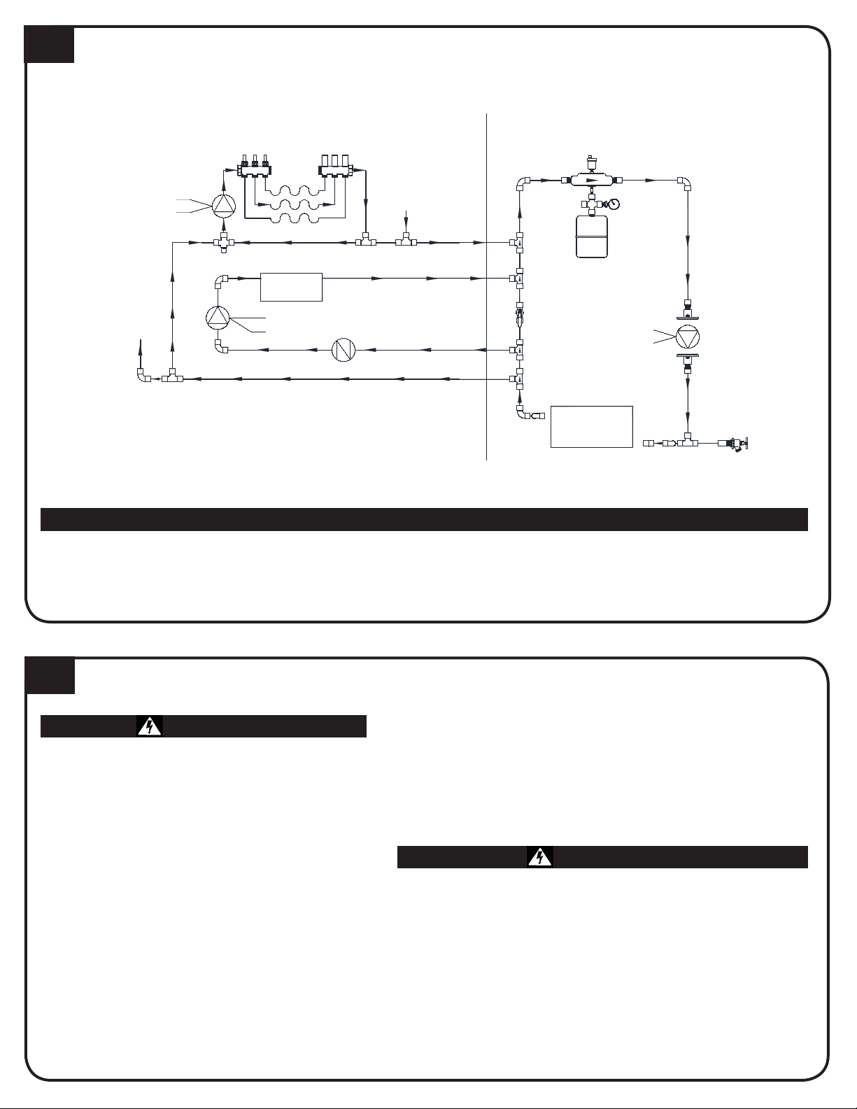
TYPICAL SYSTEM PLUMBING
(SHOWN WITH STEFFES AIR HANDLER)
It is the responsibility of the installer to prevent involuntary ow of water to the air handler. Not doing so may
cause limit tripping and/or decrease system efciency. Use of a check valve, zone valve, or other device may
help prevent involuntary ow.
Secondary Loop Primary Loop
11 PRESSURE RELIEF VALVE INSTALLATION
Risk of explosion, injury, or death. The factory
supplied pressure relief valve MUST be
connected to the system with the supplied
ttings.
1. Remove the heat exchanger access panel and locate the
pressure relief valve assembly.
2. Using the supplied union ttings, connect the pressure relief
valve to the outlet water port on the left side of the Comfort
Plus Hydronic system.
3. Use schedule 40 pipe to install a discharge line for the pressure
relief valve.
4. Install heat exchanger access panel.
Risk of injury or property damage. During operation, the
pressure relief valve may discharge large amounts of
steam and/or hot water. To reduce the potential for bodily
injury or property damage, install a discharge line.
WARNING
WARNING
IMPORTANT
Low Temp Radiant Zones
CHECK
VALVE
White
Orange
White
Black
Secondary Loop Primary Loop
Primary
Loop Pump
High Temp
Water
5100 Air
Handler
To
Other
Zones
Mixing
Valve
This Valve Must
Be Open During
Normal Operation
From
Other
Zones
Comfort +
Hydronic
Exchanger
Red
White
-
-
+
• DO NOT modify this assembly.
• DO NOT cap, plug, or otherwise
obstruct the outlet of the pressure
relief valve.
• DO mount the pressure relief valve in
a vertical and upright position.
• The pressure relief valve is sized
to service the needs of the Comfort
Plus Hydronic system. If multiple
heating systems are being used,
pressure relief valving for the other
system MUST be provided separately.
• DO use schedule 40 pipe for the discharge line.
• DO NOT use schedule 80, extra strong pipe
or connections on the discharge line.
• DO NOT cap, plug, or otherwise obstruct the discharge
pipe outlet.
• DO follow all local, state, and national codes and
regulations.
PLUMBING CONTINUED
10

13 LOW VOLTAGE PEAK CONTROL CONNECTIONS
1. Route low voltage circuit from the peak control device
to the terminal block.
2. Connect eld wiring to positions “RP” and “P”.
12 LOW VOLTAGE OUTDOOR SENSOR CONNECTIONS
The outdoor temperature sensor can be installed by wiring
it directly to the system or to the Stees Power Line Carrier
(PLC) system, if utilized.
Direct Wired:
1. Mount outdoor sensor in a location where it can
accurately sense outdoor temperature.
2. Route low voltage wire from outdoor sensor to electrical
compartment:
• Seal external wall openings.
• Outdoor sensor lead can be extended to 250 ft.
• Unshielded Class II (thermostat) wire can be used
provided it is segregated from any line voltage
wiring.
3. Connect outdoor sensor wires to “Outdoor” positions on
low voltage terminal block.
• If connecting to the Steffes Power Line Carrier
(PLC) System, follow the installation instructions
provided with the device.
• Outdoor sensor wire MUST NOT be combined with
other control wiring in a multi-conductor cable.
If utilizing a Stees Time Clock Module or PLC control,
refer to the installation instructions provided with the
device. Low Voltage Terminal Block Coding
RP = Peak Control Input Common
P = Peak Control Input
AP = Anticipated Peak (Pre-Peak) Control Input
COM = Peak Control Output Common
NC = Peak Control Output (Closed for Charge)
NO = Peak Control Output (Closed for Control)
LOW VOLTAGE ROOM THERMOSTAT WIRING
14 SINGLE ZONE APPLICATION
A 24 VAC thermostat must be used (digital recommended).
1. Disconnect power to Comfort Plus Hydronic system. Route low voltage
thermostat wire to the system.
2. Insulate thermostat wire wall opening if necessary.
3. Attach thermostat.
4. Route low voltage wire into electrical compartment to low voltage terminal block.
5. Install electrical panel cover.
IMPORTANT
IMPORTANT
P8 P9
Aux.
COM
NC
AP
NO
Relay
Outdoor Sensor
O
W/
Y1
AUX Y2 G
Outdoor
Outdoor
Y2
R
H/E 2
Y1
C
O
2 2 RP P
R C
P1
P11 D3D7D5
W E
Y1 Y2
Water
Air
P6
D1
P5
Blower
J3
J1
J2
J4
D2
To Control Board
P3
C
Blower
Speed
A
B
J5
J6
C3
D
P4 P2
Inputs
Peak
P7
LV Circuit Board
Comfort Plus
To Control Board
P10
Fid 2
RLY1
D4
D6
R2
R1
• If multiple inputs are active, system will display highest Heat Call
values."COOL" overrides all inputs and stops all heating operations.
• Systems built before 1/1/2011 are congured for 50% airow in Stage 1. For
more information, refer to Instruction #1200601-High Speed Stage 1 Relay
Installation.
• Thermostat must be programmed to energize reversing valve for cooling. If
outdoor unit used requires the reversing valve be energized for heating, see
Conguration Menu.
Inputs
Peak
P7
LV Circuit Board
Comfort Plus
To Control Board
P10
Fid 2
RLY1
D4
D6
R2
R1
P11 D3D7D5
W E
Y1 Y2
Water
Air
P6
D1
P5
Blower
J3
J1
J2
J4
D2
To Control Board
P3
C
Blower
Speed
A
B
J5
J6
C3
D
P4 P2 P1
O
W/
Y1
AUX Y2 G
Outdoor
Outdoor
Y2
R
H/E
2
Y1
C
O
2 2
RP P
R C
P8 P9
Aux.
COM
NC
AP
NO
Relay
Hydronic Heat Thermostat, Zone
Valve End Switch, or Pump Control
IMPORTANT
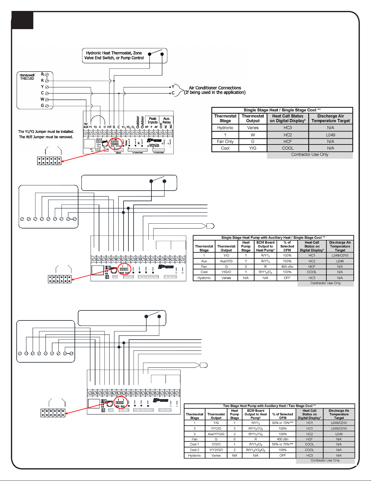
STAND ALONE FURNACE APPLICATION WITH UNCONTROLLED AIR CONDITIONER
SINGLE STAGE HEAT PUMP APPLICATION
TWO STAGE HEAT PUMP APPLICATION
A
B
C
D
W / E
Y1 / Y2
J1
J2
J3
J4
J5
J6
Blower
Speed
IMPORTANT
H/E
R C
Outdoor
Outdoor
COM
NC
NO
W/
D6
RLY1
To Control Board
D4
Fid 2
Blower To Control Board
Air
C3
P10
R1
R2
P11 D5 D7 D3
Water
Y1 Y2
W E
D2
J3
J2
J1
P5
D1
J4
P6
P4
Speed
Blower
J6
J5
C
B
A
D
P2P3
Y1
AUX OGY2 Y1 2
Y2
2 2 O
CR
Comfort Plus
LV Circuit Board
P7
W - Not Used
APPRP
Peak Aux.
Inputs Relay
The Y1/Y2 Jumper must be installed
Honeywell TH5220D
Aux
EL CG O/B RY Rc
Hydronic Heat Thermostat, Zone
Valve End Switch, or Pump Control
C - Low Voltage Common
R - Low Voltage Hot
O - Reversing Valve
Y - Compressor
To Heat Pump
Outdoor Sensor
The W/E Jumper must be removed
P9
P1
P8
IMPORTANT
A
B
C
D
W / E
Y1 / Y2
J1
J2
J3
J4
J5
J6
Blower
Speed
The W/E Jumper must be removed
The Y1/Y2 Jumper must be removed Inputs
Peak
P7
LV Circuit Board
Comfort Plus
To Control Board
P10
Fid 2
RLY1
D4
D6
R2
R1
P11 D3D7D5
W E
Y1 Y2
Water
Air
P6
D1
P5
Blower
J3
J1
J2
J4
D2
To Control Board
P3
C
Blower
Speed
A
B
J5
J6
C3
D
P4 P2 P1
O
W/
Y1
AUX Y2 G
Outdoor
Outdoor
Y2
R
H/E
2
Y1
C
O
2 2
RP P
R C
P8 P9
Aux.
COM
NC
AP
NO
Relay
Honeywell TH5320D
Aux
LY2 G CO/B
Hydronic Heat Thermostat, Zone
Valve End Switch, or Pump Control
RY R
c
C - Low Voltage Common
Outdoor Sensor
O - Reversing Valve
R - Low Voltage Hot
To Heat Pump
Y1 - Compressor
Y2 - Compressor Stage 2
W - Not Used
IMPORTANT
A
B
C
D
W / E
Y1 / Y2
J1
J2
J3
J4
J5
J6
Blower
Speed
LOW VOLTAGE ROOM THERMOSTAT WIRING CONTINUED
14

15 SOFTWARE CONFIGURATION
If access to Conguration Menu times out, the 15
amp circuit breaker must be powered off and back on
to re-enter the menu.
The Stees Comfort Plus Hydronic system has a
Conguration Menu, which allows it to be customized to the
power company and consumer’s needs. This menu can be
accessed on start-up and allows conguration settings to be
easily adjusted.
Accessing the Conguration Menu
Step 1 Energize the system. Access to the Conguration
Menu is allowed for the rst two (2) minutes of
operation. If the system has been energized for
over two (2) minutes, it must be powered o and
back on again.
Step 2 Press and release the Mbutton until the faceplate
displays “CONF.”
Step 3 Press the up arrow once and the faceplate will
display “C000.” The display will ash between
“C000” and the corresponding conguration value.
Step 4 If necessary, edit the conguration by pressing and
holding the Mbutton while using the up or the down
arrow button to change the value.
Step 5 Once the value is correct, release the buttons and
press the up arrow button to go to the next
conguration (C001, C002, etc.).
Step 6 Repeat steps 4 through 5 until all conguration
settings have been adjusted to the desired values.
Step 7 Once congured, use the down arrow to leave the
Conguration Menu.
In most applications only a few, if any, conguration changes will be necessary. Following is a description of the conguration
settings and their functions:
Part No. 1200284-6
3050 Hwy 22 North Dickinson, ND 58601-9413 www.stees.com
IMPORTANT
Power Line Carrier
(PLC) Peak Control
Configuration
Number
Outdoor
Sensor
(Factory
Default)
No
Outdoor
Sensor
Outdoor
Sensor
No
Outdoor
Sensor
Outdoor
Sensor
No Outdoor
Sensor
Outdoor
Sensor
No
Outdoor
Sensor
C000 5 5 6 5 6 5 6 5 6
C001 50°F 50°F 50°F 50°F 50°F 50°F 50°F 50°F 50°F
C002 10°F 10°F 10°F 10°F 10°F 10°F 10°F 10°F 10°F
C003
Match to the Channel
Selected at PLC
0 0 0 0 0 0 0 0
C004 8 9 8 9 8 13 12 9 8
C005 0 1 1 0 0 0 0 0 0
C006 2 2 2 2 2 2 2 2 2
C007 30 30 30 30 30 30 30 30 30
C008 5°F 5°F 5°F 5°F 5°F 5°F 5°F 5°F 5°F
C009 5°F 5°F 5°F 5°F 5°F 5°F 5°F 5°F 5°F
C010 90°F 90°F 90°F 90°F 90°F 90°F 90°F 90°F 90°F
C011
C012
C013 - C021
Refer to the Time Clock
Installation Instructions
* Risk of high temperature water. Can cause property damage. Improper water temperature settings can result in damage to the floor
covering. Make sure the maximum and minimum water temperatures (C011 and C012) are appropriate for the application
APPLICATION DEPENDENT *
APPLICATION DEPENDENT *
Low Voltage Direct
Wire Peak Control
Peak Switch Closed
for Charging
Peak Switch Open
for Charging
Line Voltage Peak
Control
Time Clock Module Peak
Control
**The value in C006 may vary, depending on the type of heat pump being installed and/or how the utility controls the heat pump.
**
Other manuals for Comfort Plus Hydronic 5120
1
This manual suits for next models
2
Table of contents
Other Steffes Heater manuals


Popular Heater manuals by other brands

DeLonghi
DeLonghi DCH5091ER instructions

Lasko
Lasko CC24842 operating manual

DELTACALOR
DELTACALOR PLATE ELECTRIC PLUS Series Operation and installation manual

HEATSTRIP
HEATSTRIP Classic THH1500AUL Operation, installation, and maintenance manual

Global
Global 653577 Assembly instructions

Rowenta
Rowenta SO2320 user guide


