STEIN GEORGIA SQUARE User manual

GEORGIA SHOWER UNIT
SQUARE (2 SIDED) AND ALCOVE
JAN 2020
IMPORTANT!
1. When you receive your Georgia Square Shower package please check for any freight damage.
2. If damage has occurred advise your supplier within 8 hours.
3. Do not install any faulty product as this will invalidate later claims.

2
WARRANTY
• This covers faulty product. Check www.stein.co.nz for full details of warranty.
• Any breakage on site will not be covered.
• The installation must conform to the instructions for the warranty to apply.
HEALTH & SAFETY
• Glass is heavy and requires two people to handle in most applications.
• Always stand glass up after unpacking the components and use soft packing when
in contact with hard surfaces. Take care not to strike an edge or corner on a hard
surface.
• All glass is toughened and cannot be reworked or drilled.
• Wear protective gloves and eye protection.
• Special care should be taken when drilling walls to avoid hidden pipes or electrical
cables.
IMPORTANT PREPARATION STEPS!
1. Solid xing must be provided in the walls behind the wall channels. 30mm centre
off outside of the acrylic tray.
2. Plumbing ttings in the wall need suitable solid xings.
3. All plumbing must be completed by a registered plumber and be in place prior to
being lined.
4. The wall lining must be a “Wet Area” grade to meet the Building Code.
5. The oor must be level and at without deection. Walls must be plumb and
surfaces at.
6. The Acrylic Tray/Liner or Quicktile Tray comes with its own specic instructions.
7. Tiling Option: Floor and walls must be waterproofed by a certied applicator and
a producers statement provided to Council authority.
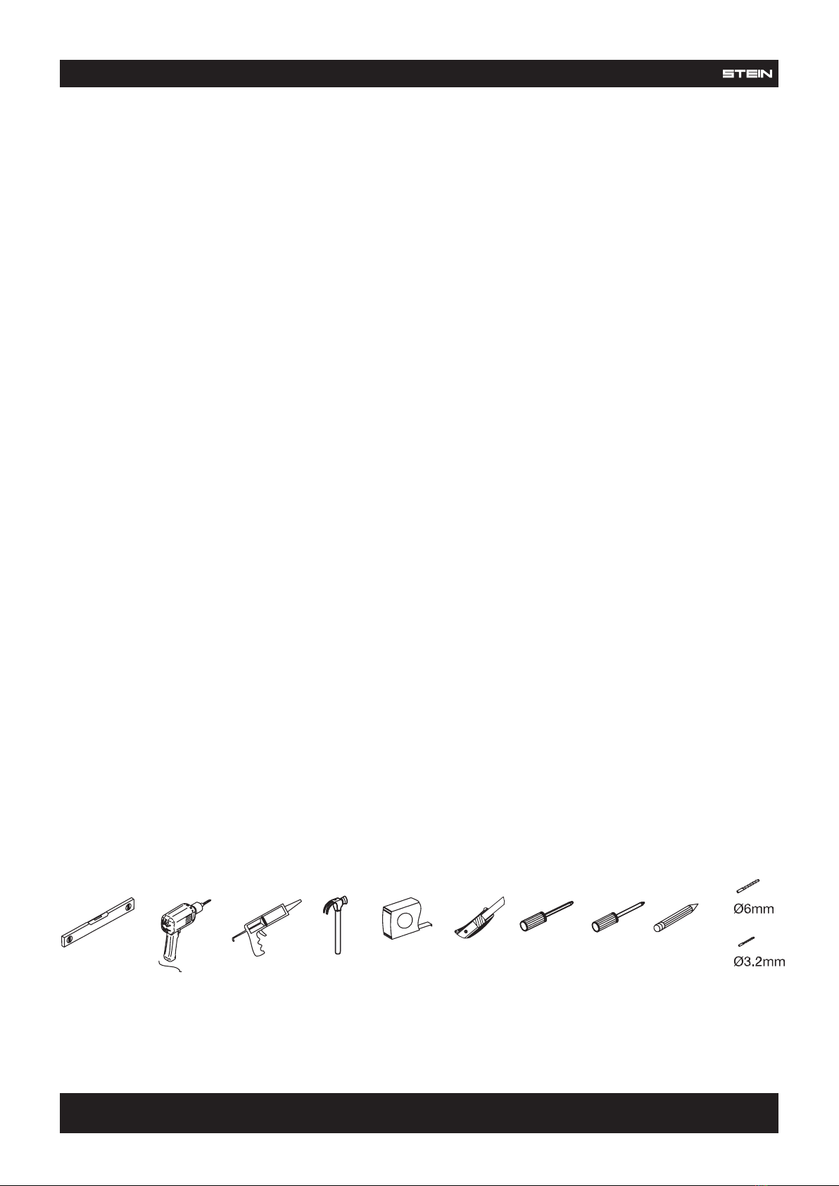
TOOLS REQUIRED (NOT SUPPLIED)
MATERIALS REQUIRED (NOT SUPPLIED)
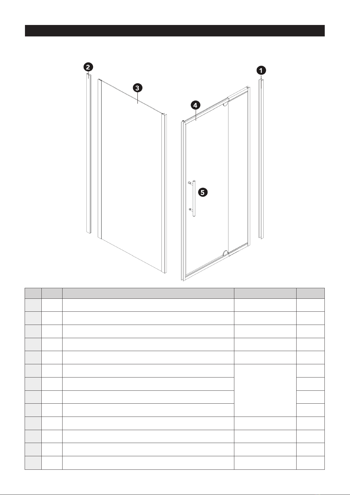
GEORGIA SHOWER UNIT SQUARE & ALCOVE – ACRYLIC INSTRUCTIONS
WE RECOMMEND A TRADESMAN FAMILIAR WITH THIS TYPE OF INSTALLATION
• Rags and suitable cleaning materials
• Sika Silaex NG Translucent

3
Before commencing installation, please ensure you have the following components in your package to
complete installation.
ASSEMBLY DIAGRAM
REF TICK DESCRIPTION PART NO. QTY
1 Door front assembly wall channels PAR5261/PAR7562 2
2 Return panel wall channel PAR5193 1
3 Fixed return panel 1
4 Door front assembly 1
5 Handle set PAR5049/PAR6633 1
6 Fixed panel screws 4 x 10mm
Screw Pack
PAR7289/PAR8514
12
7 Fixed panel screw caps 10
8Wall jamb xing screws 3.5 x 35mm 6
9 Wall plug (concrete) 6
10 Pivot block set (1 only) PAR3243/PAR6640
11 Pivot cover caps (1 only) PAR2000
12 Deector seals (Back of door and front xed glass) STE2922 2
13 Bottom door seal PAR7555 1

4
IMPORTANT:
1. Position the wall proles at 22mm off the acrylic tray edge.
2. Recalculate the specic position if tray is not level, walls are out of plumb protruding or curving
inwards more than 5mm.
LAYOUT PLAN A - 2 SIDED
SHOWER TYPE FRONT PANEL MIN/MAX RETURN PANEL MIN/MAX
900 x 750 Square (2 Sided) 830mm to 910mm 710mm to 725mm
750 x 900 Square (2 Sided) 720mm to 770mm 860mm to 875mm
900x900 Square (2 Sided) 830mm to 910mm 860mm to 875mm
1000x1000 Square (2 Sided) 930mm to 1010mm 960mm to 975mm
1200 x 900 Square (2 Sided) 1130mm to 1210mm 860mm to 875mm
1200 x 1000 Square (2 Sided) 1130mm to 1210mm 960mm to 975mm
22mm
XX
X X
MINIMUM AND MAXIMUM TABLE
Wall out of plumb will not allow the full minimum / maximum range.
INSTALLATION STEPS: PAGE 5 TO 9

5
LAYOUT PLAN B - ALCOVE (DOOR ONLY)
OPTION B: GEORGIA ALCOVE (DOOR ONLY)
Applies to 900, 1000 and 1200 sizes with tile
base and acrylic base applications.
THIS IS A BRIEF OVERVIEW OF HOW TO SET
UP A DOOR ASSEMBLY ONLY.
This runs in conjunction with the general
instruction sheet. All other installation steps
can be now followed in the general instructions
eliminating the return panel details that do not
apply.
ALCOVE TRAY NOTES
Acrylic Tray:
1. Installed rmly against the wall framing
on the three sides as per separate tray
instructions.
2. The standard liner is matched if using 10mm
Aqualine Gib or similar with clearance
each side to allow glue and any minor
discrepancies in walls.
The following table covers the door size with the minimum and maximum range. Care must be
taken if using the minimum or maximum measurements as discrepancies in the walls or base may
not allow for this.
NOTE: All measurements assume the oor is level, the walls are plumb and all surfaces are at. Any
variation must be adjusted for in the measurements provided.
SHOWER DOOR TYPE FRONT DOOR PANEL MIN/MAX
900 Door Only 830mm to 910mm
1000 Door Only 930mm to 1010mm
1200 Door Only 1130mm to 1210mm
SHOWER LINE TO TRAY EDGE
Acrylic Tray 15mm

6
INSTALLATION
1
2
3
4Slide Fixed Return Panel (3) and Door Assembly (4) into Wall Channel (1 & 2).
HINT: Insert the top or bottom corner of the panel into the channel rst. Then the rest of
the panel will slide into the channel easier.
DIAGRAM B:
Prior to wall channel xing
• Apply a short bead of silicone across tray to liner join at channel position. (Diagram A3)
• Apply a continuous 7mm bead of silicone on back of channel.
• Fix channel in place with screws checking it remains plumb. (Diagram A2)
A1 A2 A3
Go to the layout plan on pages 4 and 5 to identify the category and size of shower you are
installing. Find the applicable measurements and guidance notes that apply in your case.
Using a soft pencil or masking tape mark out the outside boundary line on the base and up the
walls with a spirit level. Use the wall channel holes to pre-drill a 2mm lead hole in the lining (refer
Diagram A1).

7
INSTALLATION
Slide the Fixed Return Panel (3) over the extrusion on to the Front Door Assembly (4) at the
leading corner. Ensure this is aligned correctly then drilled and screwed.
Using the sliding rails within the Front Door Assembly adjust them (in or out) to have both the
Fixed Return Panel and Front Door Panel positioned on the boundary line. They should be
positioned evenly between both wall channels and aligned to tray edge.
Drill and fasten off the bottom rail on the inside (Diagram D1). Using a level ensure the front
assembly and return panel are plumb vertically at the corner junction and drill and fasten the top
rail (Diagram D2).
5
6
One hole on inside
bottom rail
Two holes on top
of rail

8
INSTALLATION
Drill three equally spaced 3.2mm holes into the wall channels (1) and (2) on the INSIDE of the
screen.
Make sure that your drill holes are more than 20mm back from the glass edge when using
the smallest screen size. Otherwise you risk breaking the glass (see Diagram E).
Make sure that all the holes go though both the aluminium of the xed side panel and the door
front assembly. Fix off wall channels (1) and (2) to xed side panels (3) and (4) using the xed
panel screws (6) and covering them with screw caps (7).
A. Fasten handle to door.
B. Fit bottom door seal.
C. Fit deector seal to back of door.
D. Fit additional deector seal to leading edge of
front xed glass.
7
8
DIAGRAM E:

9
INSTALLATION
Apply silicone sealer around all external joints of shower screen a minimum of 24 hours for
silicone to set.
Silicone is not used on the inside of the shower screen because water can build up over
time within the wall channel and leak out of the shower area. The screen is designed to
allow the water to return into the shower area, if any is present. SCREENS THAT ARE
SEALED ON THE INSIDE WILL VOID WARRANTY.
9
CONTACT
Freephone: 0800 002 299 Phone: 07 928 9990 Fax: 07 928 9999
Email: info@stein.co.nz www.stein.co.nz
This manual suits for next models
1
Table of contents
Popular Shower Cabin manuals by other brands

KERRA
KERRA Splash Assembly and maintenance instructions

EAGO
EAGO LLA Series user manual

ERLIT
ERLIT ER4508TP Installation and operation instruction

Insignia
Insignia Monochrome Series installation manual

RAVAK
RAVAK SUPERNOVA SKKP2 installation instructions

Coram Showers
Coram Showers PREMIER installation instructions