STEINEL S-Former E User manual

Instruction manual
Control unit S-Former E


Table of contents
OI Control unit for S-Former E I
Table of contents
1
User guide ....................................................................... 1
1.1 Purpose of the operating instructions ...................................................1
1.2 Design of text functions.........................................................................1
1.3 Display of warnings...............................................................................2
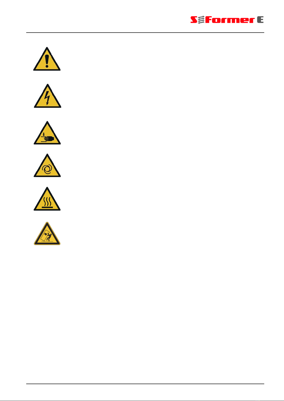
1.4 Safety symbols used.............................................................................3
2Safety ............................................................................... 4
2.1 Intended use .........................................................................................4
2.2 Reasonably foreseeable misuse...........................................................4
2.3 Dangers when handling the control unit ...............................................5
2.4 Owner obligations .................................................................................7
2.5 Obligations of the personnel .................................................................7
2.6 Labelling of the control unit and the components .................................8
Safety signs ..........................................................................................8
Identification plate .................................................................................8
3Design and function ....................................................... 9
3.1 Tapping system S-Former E.................................................................9
3.2 Control unit............................................................................................9
Control cabinet......................................................................................9
Connections on the control cabinet ....................................................10
Components in the control cabinet .....................................................11
3.3 System design ....................................................................................12
Overview .............................................................................................12
Connection interface for the cable set on the control cabinet.............13
Connection cable ................................................................................13
Connection box ...................................................................................14
Motor cable set ...................................................................................15
Instructions for correct handling of the connector plugs .....................16
3.4 Function ..............................................................................................17
Overview .............................................................................................17
Process ...............................................................................................18
4Transportation, Installation, Storage .......................... 19
4.1 Transportation.....................................................................................19
4.2 Dimensions and weight.......................................................................19
4.3 Installation...........................................................................................20
4.4 Storage................................................................................................20
5Assembly ....................................................................... 21
6Operation of the PLC .................................................... 23
6.1 Operating philosophy ..........................................................................23
6.2 Starting the control unit .......................................................................23
Starting the automatic mode...............................................................24
Starting the setup mode......................................................................25
6.3 Main menu ..........................................................................................26
Screen layout ......................................................................................26
Functions of the thread symbol .....................................................27
Structure of the main menu.................................................................28
6.4 Automatic ............................................................................................29

Table of contents
II OI Control unit for S-Former E
Quick access menu.............................................................................29
Start ...............................................................................................30
6.4.2.1 Start window....................................................................................... 30
6.4.2.2 Status window .................................................................................... 32
6.4.2.3 History ........................................................................................... 33
6.4.2.4 Trend progression and setting ...................................................... 35
Monitoring ......................................................................................38
Pneumatic .....................................................................................38
Lubrication .....................................................................................38
6.5 Setup...................................................................................................39
Quick access menu.............................................................................39
Edit ................................................................................................40
6.5.2.1 Start window....................................................................................... 40
6.5.2.2 "Station" tab........................................................................................ 42
6.5.2.3 "Pneumatics" tab ................................................................................ 43
6.5.2.4 "Drive" tab........................................................................................... 46
6.5.2.5 "General" tab ...................................................................................... 49
Load ..............................................................................................53
New ...............................................................................................53
Delete ............................................................................................56
6.6 Extras ..................................................................................................56
Quick access menu.............................................................................56
Archive ..........................................................................................57
6.6.2.1 Start window....................................................................................... 57
6.6.2.2 Measurement curves ..................................................................... 57
6.6.2.3 Trend progression ........................................................................ 58
6.6.2.4 Statistics ........................................................................................ 60
6.6.2.5 Log protocol .................................................................................. 62
User ...............................................................................................63
6.6.3.1 Start window....................................................................................... 63
6.6.3.2 Log in user, select language .............................................................. 64
6.6.3.3 System settings ............................................................................. 65
6.6.3.4 User administration ....................................................................... 68
6.6.3.5 Data backup ................................................................................. 69
6.6.3.6 Program data ............................................................................... 70
6.6.3.7 IP addresses ................................................................................. 70
6.6.3.8 Signal logic ................................................................................... 72
6.6.3.9 Fault signal ................................................................................... 72
6.6.3.10 Drive parameters ........................................................................ 73
Date/Time ......................................................................................74
Help ...............................................................................................75
6.6.5.1 Instructions ................................................................................... 75
6.6.5.2 Remote maintenance ................................................................... 75

Table of contents
OI Control unit for S-Former E III
6.6.5.3 Information .....................................................................................76
6.7 Process monitoring .......................................................................77
Measurement OK................................................................................79
Measurement NOK .............................................................................79
Setting process monitoring ...........................................................80
Setting the tolerance ................................................................81
Smoothing ................................................................................83
Widening ..................................................................................85
Window function .......................................................................86
Checking and sending settings...........................................................87
6.8 PLC diagnostics .............................................................................88
Overview .............................................................................................90
Drive data............................................................................................93
PLC communication............................................................................94
PLC outputs ........................................................................................95
PLC inputs ..........................................................................................96
6.9 Tips and notes for using monitoring....................................................97
Cycle time monitoring .........................................................................97
Trend monitoring.................................................................................98
Envelope monitoring ...........................................................................99
6.10 Documentation for data management ..............................................102
Program data ..............................................................................102
Process monitoring .....................................................................102
Reference curve................................................................................103
Tolerance curve ................................................................................103
Measurement curve .....................................................................103
Saving the measurement data on the panel.....................................103
History .........................................................................................105
Statistics ......................................................................................105
Trend ...........................................................................................108
Log protocol ................................................................................109
Signal flow diagram...........................................................................110
7Maintenance, repair .................................................... 112
7.1 Safety instructions.............................................................................112
7.2 Maintenance schedule......................................................................114
8Disposal....................................................................... 115
9Technical data ............................................................. 116
10 List of symbols............................................................ 119
11 List of figures .............................................................. 122

Table of contents
IV OI Control unit for S-Former E

1 User guide
OI Control unit for S-Former E 1
1
User guide
1.1 Purpose of the operating instructions
These operating instructions are part of the control unit for the S-Former E. They
facilitate the safe handling of the control unit. The instructions of component suppli-
ers and local accident prevention regulations also apply.
Only commission the control unit after you have read and understood the operating
instructions.
It is imperative that you observe the safety instructions.
Always store the operating instructions at the site of operation of the control unit.
The operating instructions must be readily accessible for all operating and mainte-
nance personnel.
1.2 Design of text functions
⚫This dot identifies the descriptions of tasks that you must perform.
–This line identifies enumerations.
This asterisk identifies cross references.
If cross references to other chapters are necessary within the text, notations are
abbreviated for reasons of clarity.
Example: OI, 2 Safety instructions
This means: Refer to operating instructions,
Chapter 2 Safety instructions
If the cross reference refers to a page, figure or position number, then this infor-
mation will be added at the end of the cross reference.
Example: Fig. 4-4, Pos. 1
This means: refer to (in chapter 4 of this manual)
position number 1 of figure 4.
(3) Numbers in parentheses refer to positions in figures.

1 User guide
2 OI Control unit for S-Former E
DANGER!
WARNING!
CAUTION!
ATTENTION!
1.3 Display of warnings
This signal word indicates a danger with a high degree of risk, which if not
avoided, can result in fatal or serious injury.
This signal word indicates a danger with a medium degree of risk, which if not
avoided, can result in fatal or serious injury.
This signal word indicates a danger with a low degree of risk, which if not avoided,
can result in minor or moderate injury.
This signal word indicates a potentially dangerous situation.
Failure to comply with safety regulations may result in damage to the product or
environmental damage.
Notes, tips and recommendations as well as information on efficient and failure-
free operation.

1 User guide
OI Control unit for S-Former E 3
1.4 Safety symbols used
This symbol stands for a potentially imminent danger to the life and health of per-
sons.
Failure to observe these instructions could lead to serious damage to your health
all the way up to life-threatening injuries.
This symbol is a "Warning of dangerous electrical voltage" (even when the main
switch is switched off).
Only those persons may perform tasks that have the required expertise (e.g. elec-
tricians or electrically instructed persons) and the required authorisation of the
owner.
This symbol indicates a "Warning of hand injury".
There is a risk of injury from moving machine parts.
This symbol indicates a "Warning of automatic start".
There is a risk of injury from moving machine parts.
This symbol indicates a "Warning of a hot surface".
Exposure to hot surfaces may result in burns.
This symbol indicates a "Warning of tipping hazard".
Take care when handling the top-heavy control cabinet.

4 OI Control unit for S-Former E
ATTENTION!
2 Safety
2.1 Intended use
The control unit is built based on best available technology and accepted safety-
related rules.
Only use the control unit as intended and in excellent safety-related condition.
Immediately rectify faults that compromise safety.
The control unit is used to operate, control, set up and parametrise the S-Former-E
system. The control unit may only be used in connection with tapping units of the
type S-Former E with AC servomotor and it is intended for integration into a super-
ordinate machine and a superordinate control unit.
The control cabinet and the PLC are part of the control unit.
The parameters defined in Chapter 9, Technical data, Page 116 must be ad-
hered to at all times.
Intended use also includes:
–observing all instructions included in the operating instructions and the manu-
facturer's documentation of the components,
–adhering to inspection and maintenance cycles,
–assigning only qualified and authorised professionals and operators to the re-
spective tasks,
–the exclusive use of original parts.
2.2 Reasonably foreseeable misuse
A use not defined as "intended use" or a use that exceeds the intended use is con-
sidered to be an unintended use and is prohibited.
For damages resulting from an unintended use
–the owner bears the sole responsibility,
–the manufacturer assumes no liability.

3 Safety
OI Control unit for S-Former E 5
DANGER!
Non-intended uses that can possibly be expected to occur are:
–Operation of the control unit with connected loads different from those stated in
Chapter 9, Technical data, Page 116.
–Connection of devices other than the tapping units of the type S-Former E.
–Unauthorised additions, modifications or changes to the control cabinet and the
PLC.
–Operation of a tapping unit by hand without installation in a superordinate ma-
chine or without integration in a superordinate control unit.
–Operation of the control unit with a tapping unit without a protective device at
the action point of the roll tap.
–Operation of the control unit when the tapping unit is in setup mode and is not
visible from the display of the control cabinet.
–Laying the compressed air line through the control cabinet.
2.3 Dangers when handling the control unit
When performing tasks in the control cabinet, there is a danger of suffering serious
and life-threatening injuries by coming into contact with live parts.
Even when the main switch is switched off, voltage remains between the power
supply and the main switch.
Prior to performing any task, disconnect the control cabinet and prevent a restart.
Disconnect the control cabinet when working between the power supply and the
main switch by completely pulling the plug out of the power supply.
Work at the electrical equipment may only be performed by electricians or trained
personnel under the supervision of an electrician in accordance with electrotech-
nical regulations.
The electricians must have knowledge of the power supply, how it can be switched
off and the implementation instructions as per the German accident prevention reg-
ulations (BGV A3).
Check the electrical equipment on a regular basis.
Immediately replace loose connections or singed cables.
Always keep the control cabinet locked. Only authorised personnel with keys or
tools have permission to access it.

6 OI Control unit for S-Former E
WARNING!
WARNING!
CAUTION!
WARNING!
A warning message appears prior to the start of a movement. The roll tap starts
automatically once this message has been confirmed.
When the operating mode is activated, the motor is supplied with power and the
cylinder is pressurised.
In setup mode, movements can be performed at any time and independently from
the superordinate control unit.
Prior to confirming the message, make sure that there are no persons in the dan-
ger area, e.g. those performing maintenance tasks.
There is a risk of injury from moving machine parts.
Set up the control cabinet in a way so that the tapping unit is visible from the dis-
play during setup tasks and functional tests.
There is a danger of injury from malfunctions and the unexpected start of the tap-
ping unit heads.
Make sure that nobody is in the danger area prior to roll tap movements.
Do not loosen or tighten motor or resolver cables when the control unit is switched
on.
Do not modify the electrical parts in any way.
Only operate the overall system consisting of control unit and tapping units when
the control cabinet doors are closed.
Protect the control unit from liquids, dust and dirt.
Make sure that the control unit's maximum operating temperature of 40 °C is not
exceeded.
The motor and the roll tap can become very hot during operation. There is a risk of
burns.
Do not touch the components or wear safety gloves. Allow the components to cool
down to room temperature prior to touching them.

3 Safety
OI Control unit for S-Former E 7
CAUTION!
The tapping units connected to the control unit are sensitive to external magnetic
fields. Make sure that no external magnetic fields are present that could influence
the function of the magnetic monitoring on the cylinder piston of the tapping unit
heads.
2.4 Owner obligations
The owner commits to only allow persons to work at the components who
–are familiar with the basic regulations concerning occupational safety and acci-
dent prevention,
–have been trained and instructed in the tasks that are to be performed,
–have read and understood these operating instructions.
The owner also commits to
–clearly assign responsibilities with regard to operation, maintenance and re-
pairs,
–observe the requirements of workplace directive 89/654/EEC and directive
2009/104/EC on the use of work equipment.
2.5 Obligations of the personnel
All persons tasked with working at the components commit to
–observe basic regulations concerning occupational safety and accident preven-
tion,
–read and observe the safety chapter and the safety instructions of these operat-
ing instructions prior to beginning work.

8 OI Control unit for S-Former E
ATTENTION!
2.6 Labelling of the control unit and the components
Safety signs
Observe all warnings and safety instructions as well as other signs attached to the
control unit and the tapping unit.
Make sure that all safety instructions and warning notices are legible and replace
them if necessary.
Warning of dangerous electrical voltage
This pictogram is posted at the control cabinet door above the main switch, on the
AC servomotors of the tapping units and on the connection boxes.
Warning of hot surface
This pictogram is attached to the AC servomotors of the tapping units.
Identification plate
The identification plate is affixed to the control cabinet.
Fig. 2-1 Identification plate
The identification plates of the individual components can be found on these com-
ponents as well as the documentation of the respective manufacturer.

3 Safety
OI Control unit for S-Former E 9
3 Design and function
3.1 Tapping system S-Former E
The tapping system S-Former E is used for the automated production of internal
threads in prepared parts. Roll tap heads in various sizes are available for machin-
ing depending on the required power and torque.
Up to four tapping unit heads of different sizes per tapping system can be con-
trolled and regulated via a PLC control unit.
Reusable machining programs are created and parametrised via the touch panel of
the control cabinet. Settings for the drives and monitoring methods for determining
good or bad parts can be selected and adjusted independently of each other. This
monitoring enables production to be stopped in good time in the event of a fault
and can thus prevent the production of bad parts or damage to the tool and tapping
unit head.
3.2 Control unit
Control cabinet
The control unit for the S-Former-E system is located in a control cabinet. Inter-
faces for all control unit inputs and outputs are provided on the control cabinet. De-
pending on the number of built-in drive controllers and parallel tapping unit heads,
the control cabinet is supplied in single, double, triple and quadruple versions. The
basic dimensions of the control cabinet remain unchanged.
The control cabinet is equipped with a cart for mobile use and ergonomic opera-
tion.
Fig. 3-1 Control cabinet with control unit

10 OI Control unit for S-Former E
Connections on the control cabinet
The following connections and components are located on the control cabinet:
Fig. 3-2 Exterior of the control cabinet
1Filter fan outlet
22 x RJ45 network connection
3Connection for Emergency Stop to the superordinate control unit, e.g. a press
4USB interface
512" touch panel PC with Win7 operating system
6Door locks
7Dummy plates for up to three additional outlet plug connections
8Connecting socket for lubrication system
9Connecting socket for the signal of the superordinate control unit, e.g. a press
10Main power supply 400 VAC
11Main switch
12EMERGENCY STOP button
13Filter fan inlet
14Outlet plug connection, single version shown here
7
1
2
4
3
5
6
7
8
9
13
11
10
12
14
7
6

3 Safety
OI Control unit for S-Former E 11
Components in the control cabinet
The control cabinet contains the following components:
Fig. 3-3 Interior of the control cabinet
Fig. 3-4 Optional router
124 VDC supply
2Emergency stop relay
3Input/output block
4Assembly locations for up to three additional drive controllers
5Drive controller with PLC control unit
6Optional: Expansion with LTE router or WLAN for remote maintenance or net-
work factory connection
Please see the connection diagrams for detailed information on the components in
the control cabinet.
4
1
2
5
4
6
3

12 OI Control unit for S-Former E
3.3 System design
Overview
The entire system consists of the following components:
Fig. 3-5 Design of the entire system
1Tapping unit heads, up to four pieces, parallel operation of different sizes
2Cable set (electrical and pneumatic) from the connection box to the tapping unit
head, length approx. two metres
3Connection boxes with the introduction of the pneumatics
4Electrical connection cables from the control unit to the connection box, length
approx. five metres
5Control cabinet with control unit for up to four tapping unit heads
6Pneumatic valves, mounted on the connection box
7Pneumatic supply for connection boxes
8Compressed air maintenance unit with pressure reducer
9Optional: Minimum quantity lubrication system/other lubrication system
10Optional: Spray nozzles
Electrical connection
Pneumatic connection
Connection to lubrication system (optional)
The power supply (400 VAC/16 A) and the pneumatic supply (6 bar) must be pro-
vided at the installation site.
No residual current device or only one residual current device with a sufficiently
high permissible residual current (min. 100 mA) may be used for the power supply.
The compressed air supply must be at least 6 bar. The actual working pressure,
typically 2–3 bar, is adjustable via the pressure reducer.
All plugs and sockets have die-cast aluminium housings with optimised EMC prop-
erties and protection class IP65 when plugged in and IP20 when not plugged in.
1
2
3
6
5
10
9
4
8
7
2
1
6
4
3

3 Safety
OI Control unit for S-Former E 13
Connection interface for the cable set on the control cabinet
A connecting socket at the control cabinet is designated for each tapping unit head.
The number of connecting sockets depends on how many tapping unit heads the
control cabinet is designed for. Example: Quadruple control cabinet four pieces
connecting sockets for four tapping unit heads.
Fig. 3-6 Connecting socket (rotated by 90°)
1Dummy module
212-pin module for I/Os
38-pin GigaBit module for motor encoder
48-pole module for motor power
Connection cable
The connection cable is the connection between the control cabinet and the con-
nection box. It has a plug and a socket connection.
The cable set is protected by a black corrugated plastic hose. The signal and volt-
age transfer from the control cabinet to the connection box is 1:1.
Fig. 3-7 Connection cable Socket connection Plug connection
1Connection cable from the control unit to the connection box
2Connection to the connection box
3Connection to the control cabinet
Please see the connection diagrams for detailed information on the configuration.
1
2
3
4
1
2
3

14 OI Control unit for S-Former E
Connection box
The connection box serves as an interface between the tapping unit head and con-
trol cabinet.
The interface connections and a pneumatic switching valve are installed on the
outside, the compressed air is fed directly into the connection box.
Fig. 3-8 Connection box, interfaces
1Connection box, overall view
2Motor cable set connection to tapping unit head
3Connection cable connection to control cabinet
4Pneumatic module with stop valve
517-pin module for I/Os
68-pin GigaBit module for motor encoder
78-pole module for motor power
Connection box side views:
Fig. 3-9 Connection box side views, left, front, right
1Supply of the pneumatic system into the box
2Switching valve for the pneumatic system
3Outputs for the electrical supply of the switching valve
1
2
3
5
4
6
7
1
2
3
Other manuals for S-Former E
1
Table of contents
Other STEINEL Control Unit manuals
Popular Control Unit manuals by other brands

SMC Networks
SMC Networks VV100 Series Installation and maintenance manual

DFI
DFI DV970 user manual

Telit Wireless Solutions
Telit Wireless Solutions HE920 Series Product description

Sony
Sony BKS-R3219 Operation manual

Watts
Watts 909 Series Installation, maintenance & repair

WAREMA
WAREMA Minitronic Dialog Operating and installation instructions

Honeywell
Honeywell D05FS-A Series installation instructions

Clack
Clack Water Specialist CI Programming manual

Mutable Instruments
Mutable Instruments Kinks Installation

Samson
Samson 3248 Mounting and operating instructions

Dräger
Dräger BS8468-1 Instructions for use

Trenz Electronic
Trenz Electronic TE0720 Schematics