Steiner 75-70709 User manual

OP/PARTS MANUAL
MAN 4158524
Rev. A 4-2007
MODEL:
75-70709
CAB FOR 220 TRACTOR CB220
CALIFORNIA
Proposition 65 Warning
Diesel engine exhaust and some of
its constituents are known to the State
of California to cause cancer, birth
defects and other reproductive harm.
Californie Proposition 65
Avertissement
Les échappements des moteurs diesel
et certains de leurs composés sont
reconnus par l’Etat de Californie pour
être cancérigènes, provoquer des
défauts congénitaux et d’autres dangers
en matière de reproduction.
ADVERTENCIA
AVERTISSEMENT
WARNING
The engine exhaust from this product
contains chemicals known to the State
of California to cause cancer, birth
defects or other reproductive harm.
California Advertencia
de la Proposicion 65
El estado de California hace saber que
los gases de escape de los motores
diesel y algunos de sus componentes
producen cáncer, defectos de
nacimiento y otros daños en el
proceso de reproducción humana.
L’
é
mission du moteur de ce mat
é
riel
contient des produits chimiques que
l’Etat de Californie consid
è
re
ê
tre
canc
é
rig
è
nes, provoquer des d
é
fauts
cong
é
nitaux et d’autres dangers en
mati
è
re de reproduction.
El estado de California hace saber
que los gases de escape de este
producto contienen productos
quÍmicos que producen cáncer,
defectos de nacimiento y otros daños
en el proceso de reproducción
humana.
CALIFORNIA
Proposition 65 Warning
Battery posts, terminals, wiring
insulation, and related accessories
contain lead and lead compounds,
chemicals known to the State of
California to cause cancer and birth
defects or other reproductive harm.
WASH HANDS AFTER HANDLING.

1
TURF UNIT
CAB
IMPORTANT MESSAGE
Thank you for purchasing this CGC, Inc. product. You have purchased a world class product, one of the best
designed and built anywhere.
This product comes with an Owner/Operator's Manual. The useful life and good service you receive from this
product depends to a large extent on how well you read and understand this manual. Treat this product properly
and adjust it as instructed, and it will give you many years of reliable service.
See a CGC, Inc. dealer for any service or parts needed. CGC, Inc. service ensures that you continue to receive
the best results possible from CGC, Inc. products. You can trust CGC, Inc. replacement parts because they are
manufactured with the same high precision and quality as the original parts.
CGC,Inc.designsandbuildsitsequipmenttoservemanyyearsinasafeandproductivemanner. Forlongestlife,
usethisproductonlyasdirectedinthemanual,keepitingoodrepairandfollowsafetywarningsandinstructions.
You'll always be glad you did.
Commercial Grounds Care, Inc.
One Bob Cat Lane
Johnson Creek, WI 53038-0469
4-2007
TABLE OF CONTENTS FIGURES PAGE
DESCRIPTION / SPECIFICATIONS .............................................................................................................. 2
SAFETY ..................................................................................................................................................... 3, 4
INSTALLATION / REMOVAL .......................................................................................................................... 5
ASSEMBLY INSTRUCTIONS.................................................................................................................... 6-14
PARTS SECTION......................................................................................................................................... 15
CAB PARTS (1) .................................................. FIGURE 1.................................................................. 16, 17
CAB PARTS (2) .................................................. FIGURE 2.................................................................. 18, 19

2
TURF UNIT
CAB
DESCRIPTION / SPECIFICATIONS
SPECIFICATIONS
OverallHeight-Installed ................................................... 69"
Overall Width................................................................... 43-1/2"
Cab Length...................................................................... 44"
Head Room ..................................................................... 41-1/2"
Inside Roof Width............................................................ 41"
Roof Length..................................................................... 31"
Roof Width (outside) ....................................................... 42"
Safety Laminated Glass .................................................. Windshield and Rear Window
Windshield Wiper ............................................................ Electric, 12 volt
Doors............................................................................... Steel Frame, Fabric Covered
Mounting ......................................................................... Frame and ROPS Roll Bar
DESCRIPTION
The sturdy CB220 cab is carefully designed to fit the Model 220 2 X 4 TURF UNIT equipped with
a ROPS roll bar. It is extremely useful in cold weather when operating a snowblower or a power angle blade.
Exceptional features include ease of entry from either side, full glass windshield, back window and lightweight
removable doors. Supported by the ROPS roll bar and equipped with a seat belt, the operator has added
comfort and safety protection. Overall visibility is good with the cab installed.
A windshield wiper is standard equipment. Additional lights and safety lights may be added as desired
by the owner.
3
TURF UNIT
CAB
NOTICE !!!
Unauthorized modifications may present extreme
safety hazards to operators and bystanders and
could also result in product damage.
Commercial Grounds Care, Inc. strongly warns
against, rejects and disclaims any modifications,
add-on accessories or product alterations that are
not designed, developed, tested and approved by
CGC,Inc. Engineering Department. Any CGC, Inc.
product that is altered, modified or changed in any
manner not specifically authorized after original
manufacture–includingtheadditionof“after-market”
accessories or component parts not specifically
approved by CGC, Inc.–will result in the CGC, Inc.
Warranty being voided.
Anyandallliabilityforpersonalinjuryand/orproperty
damagecausedbyanyunauthorizedmodifications,
add-on accessories or products not approved by
CGC,Inc.willbeconsideredtheresponsibilityofthe
individual(s) or company designing and/or making
such changes. CGC, Inc. will vigorously pursue full
indemnificationandcostsfromanypartyresponsible
for such unauthorized post-manufacture
modifications and/or accessories should personal
injury and/or property damage result.
This symbol means:
ATTENTION!
BECOME ALERT!
Your safety and the safety of others is involved.
Signal word definitions:
Thesignalwordsbelowareusedtoidentifylevelsof
hazard seriousness. These words appear in this
manual and on the safety labels attached to CGC,
Inc. machines. For your safety and the safety of
others, read and follow the information given with
thesesignalwordsand/orthesymbolshownabove.
DANGER indicates an imminently hazardous
situationwhich, if not avoided,WILL resultin death
or serious injury.
WARNINGindicatesapotentiallyhazardoussituation
which, if not avoided, COULD result in death or
serious injury.
CAUTIONindicatesapotentiallyhazardoussituation
which,ifnotavoided,MAYresultinminorormoderate
injury. It may also be used to alert against unsafe
practices or property damage.
CAUTION used without the safety alert symbol
indicates a potentially hazardous situation which, if
not avoided, MAY result in property damage
MODEL NUMBER: This number appears on
sales literature, technical manuals and price lists.
SERIAL NUMBER: This number appears only
on your mower. It contains the model number
followed consecutively by the serial number. Use
this number when ordering parts or seeking
warrantyinformation.
SAFETY
4
TURF UNIT
CAB
SAFETY
1. Read and understand the Owner’s Manual before attempting to operate this machine.
2. Operate all controls from the operator’s seat. NO RIDERS.
3. Keep all shields in place and safety switches adjusted properly.
4. Do not leave equipment unattended. STOP the engine and remove the key.
5. Do not allow minors or the inexperienced to operate this machine.
6. Keep people and pets a safe distance away from machine using power driven attachments. Injury could
result from flying debris.
GENERAL SAFETY
OPERATING SAFETY
1. DO NOT attempt to work on unit or any
attachments with the engine running. STOP
ENGINE!
The tractor may coast when the engine stops.
2. Before leaving the tractor seat:
•Disengage PTO.
•Set Parking Brake.
•Stop Engine.

5
TURF UNIT
CAB
INSTALLATION / REMOVAL
INSTRUCTIONS FOR MOUNTING ASSEMBLED CAB ON 220 TURF UNIT
NOTE: Detailed Cab Assembly Instructions are found in the assembly instructions found on Pages 7-16.
1. Turf Unit must be equipped with a roll bar.
2. Remove 3 roll bar mounting bolts on each side where the cab mounts.
3. With the cab doors removed, position the assembled cab into position around the roll bar.
4. Fasten the cab to the roll bar with the “U-type” clamps and 3/8 X 3 bolts. Install the front lower corners to
the front fenders and dash side panels with 5/16 X 1/2 flange bolts.
NOTE: The top bolt of the dash side panel uses existing bolt (230 only). Model 220 needs holes drilled in
the dash. See Page 9, Step 11.
5. Replace roll bar mounting bolts removed in step 2.
6. Install the cab doors and check for proper latch closure. Adjust latches as needed. See Page 13, Step
23 for adjustments.
7. Connect wiring for the wiper motor.
INSTRUCTIONS FOR REMOVING ASSEMBLED CAB FROM 2 X 4 TURF UNIT
1. Disconnect wiring to wiper motor.
2. Remove the doors.
3. Remove the bolts at the front fenders and dash side panels.
4. Remove the 3 bolts that support the roll bar and cab on each side.
5. Remove the “U—type” clamps which clamp the cab to the roll bar.
6. Get an assistant to help and carefully lift the cab up and away from the roll bar.
7. The roll bar may remain on the turf unit.
8. Replace the bolts as needed with the cab removed.

6
TURF UNIT
CAB
ASSEMBLY INSTRUCTIONS
1. Have a ROPS approved roll bar and seat belt
mounted to your tractor, using the roll bar
instructions.
NOTE: Cab mounting uses 3 roll bar mounting
bolts Aon each side as shown.
2. Disconnectbattery.
3. Open the hardware package and sort the bolts
and nuts according to size.
4. Facing the dashboard, remove the 3/8 flange
bolts Bat the top of the side panels, one from
each side. (Model 230 only; Model 220 needs
holes drilled in the dash. Refer to Step 11.)
5. Do not completely tighten bolts in Steps 5-20.
Cab will be aligned in Step 23.
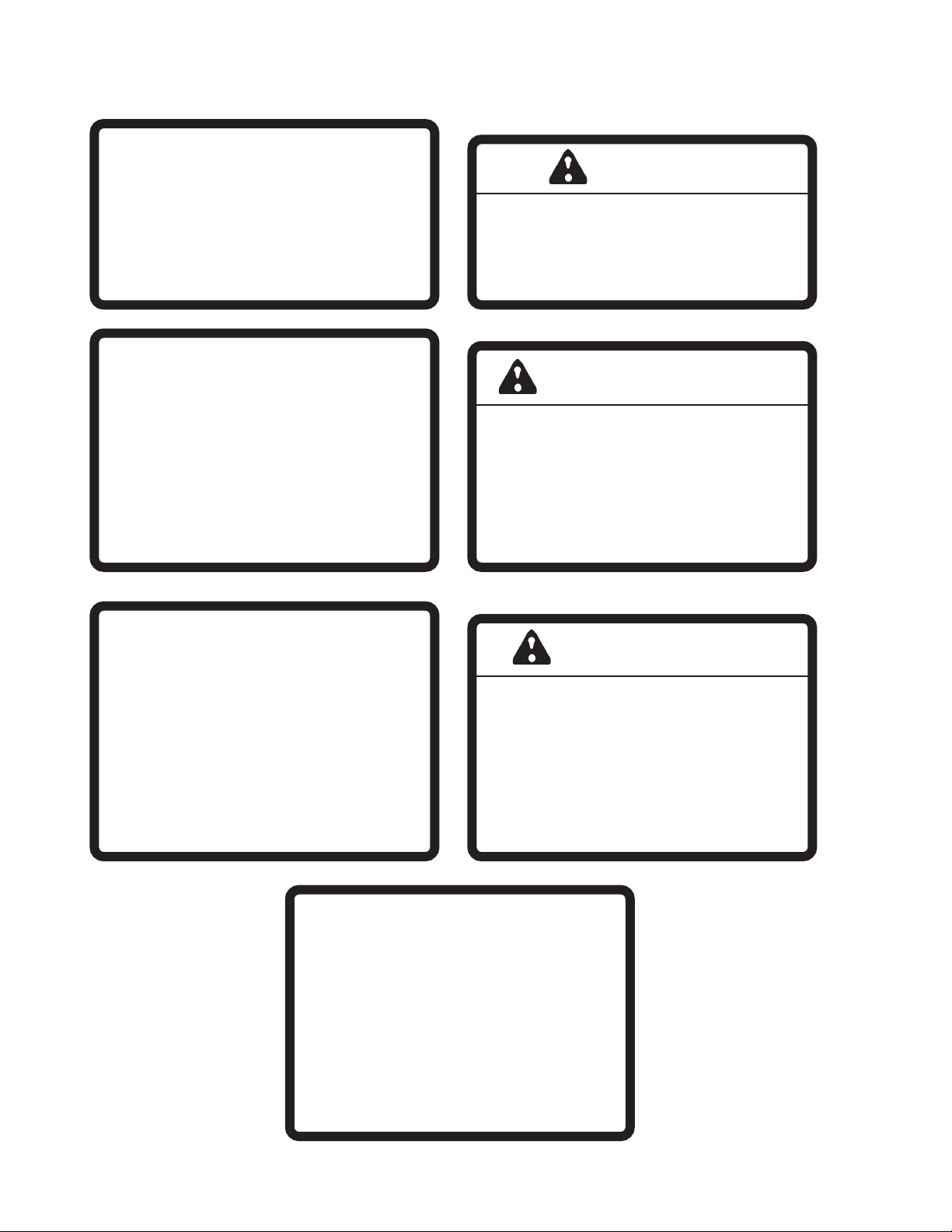
6. Assemble the cab roll bar supports Cusing (4)
3/8 X 3" bolts. Place a 3/8 flat washer on each
end of the bolt and loosely tighten with 3/8 nuts
and lockwashers. Position the bracket so the
closed end is facing to the side and away from
the tractor as shown.
7
TURF UNIT
CAB
ASSEMBLY INSTRUCTIONS
7. Install the rear side panels Daligning the 3
bottom holes with the bottom holes of the roll bar.
Fasten using the (6) bolts remaining from the roll
bar installation.
8. Position the roll bar supports Cwith the slots at
the top of the side panels Dand fasten with a
3/8 X 3/4 flange bolt and flange nut.
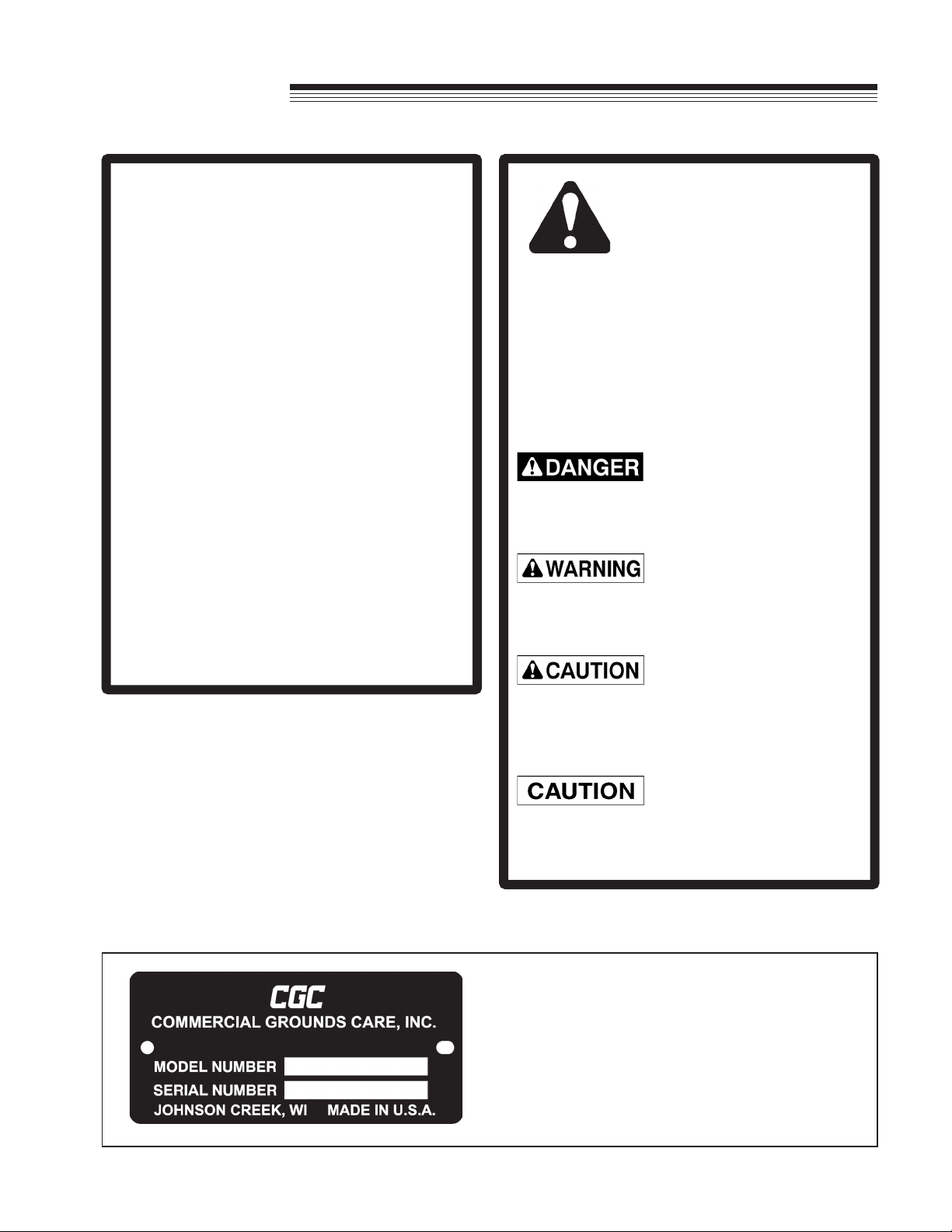
9. Install door hinge pins Eto rear side panels by
inserting pin in top hole until punched holes line
up. Bolt together using 5/16 X 3/4 flange bolts
and flange nuts.
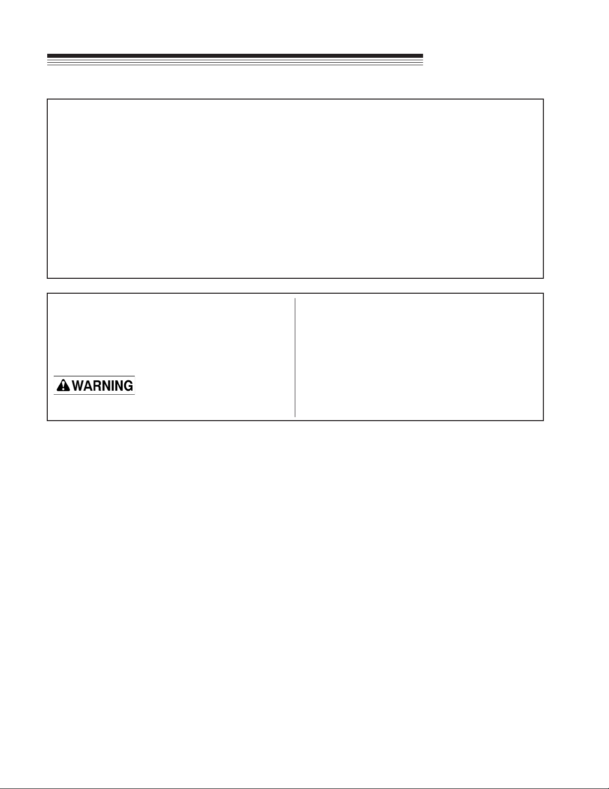
10. Cut and place self—adhesive foam strips Fon
the flanges of the front lower panels.

8
TURF UNIT
CAB
ASSEMBLY INSTRUCTIONS
Line up the post Iwith the edge of the fender J.
Making sure the post is square with the fender, mark
and drill (2) 13/32" holes for the 3/8 bolts.
11. Reinstall the front lower panel using the 3/8
flange bolts in the top hole and 5/16 X 1/2 flange
bolts in the lower hole.
9
TURF UNIT
CAB
ASSEMBLY INSTRUCTIONS
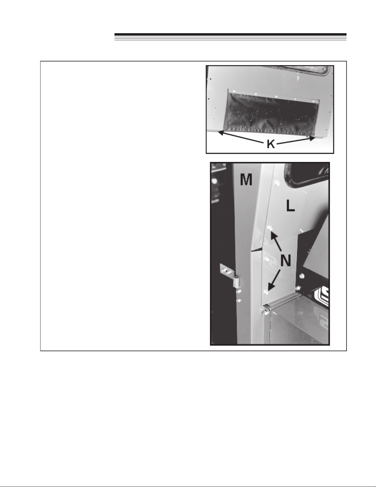
12. Cut and place self-adhesive foam strips Kon the
bottom of the rear window panel as shown.
13. Fasten the rear window panel Lto the side
panels Musing 5/16 X 1/2 flange bolts and nuts
N. Do not tighten until Step 21. If seatbelt
interferes, slide the plastic cover forward on the
mounting bracket.

10
TURF UNIT
CAB
ASSEMBLY INSTRUCTIONS
14. Remove top bolts on hood.
15. Mount front window panel to lower front panels
using 5/16 X 1/2 flange bolts and nuts.
16. Install trim on filler plate close to front of cab and
tractor using trim with bulb on top as shown.
Use hood bolts to install plate to hood, to close
the space between the cab and the tractor as
shown.

11
TURF UNIT
CAB
ASSEMBLY INSTRUCTIONS
17. Place the roof section down over rear side, rear
window panels and front window panel as shown.
Fasten with 5/16 X 1/2 flange bolts and nuts. Do
not tighten at this time.
18. Mark and drill a 13/32" hole at location Pthrough
the remaining hole in the lower front panel and
fasten to the fender with a 5/16 X 1/2 bolt.
19. Mount door hinges Qon doors as shown using
5/16 X 3/4 flange bolts, 1/4 flat washers and
5/16 flange nuts. You may want to tighten these
bolts now, then loosen them later for adjustment.
20. Mount door on hinges.

12
TURF UNIT
CAB
ASSEMBLY INSTRUCTIONS
21. Now look at the alignment of the assembled cab. With all the bolts still loose you can move the panels to
obtain a good fit around the door opening. Adjust door hinges and/or cab.
22. Tighten all bolts at this time.
23. Install door handle as shown in illustration below.
13
TURF UNIT
CAB
ASSEMBLY INSTRUCTIONS
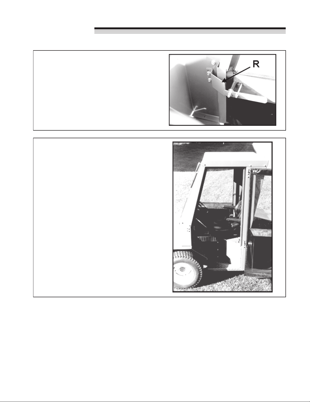
24. Mount striker plate Ras shown. Adjust striker
plate and latch so door will open and close
freely.
25. With the door mounted and latched, draw the
outline of the door in pencil. This will aid you in
installing the weatherstrip along (3) sides of the
opening as shown in Photo. A final adjustment
of the striker plate and latch may be required
after the weatherstrip is installed.
NOTE: Door may require bending slightly for best
fit.
14
TURF UNIT
CAB
ASSEMBLY INSTRUCTIONS
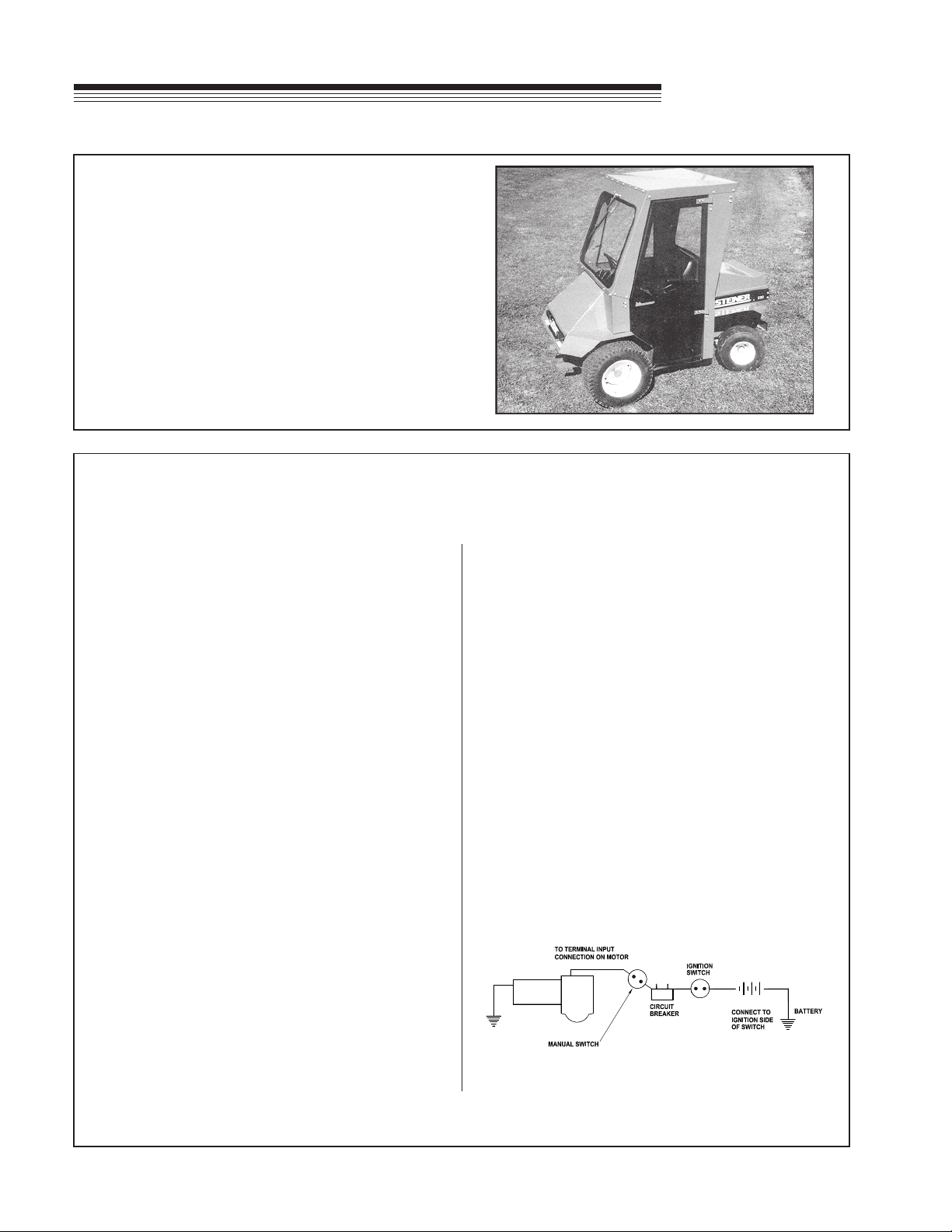
26. Mount the wiper above the windshield according
to the wiper instructions. Check the wiper blade
path so that it does not contact the rubber
molding. Wiper position should be set at 85
degrees. Refer to the wiper instructions for
position adjustment. Fasten the inline fuse to the
auxiliary side of the circuit breaker and route the
wire to the wiper.
WWF WINDSHIELD WIPER
INSTALLATION
(Except 1000 Series)
1. Locate mounting position of wiper assembly.
2. Determine whether adequate space is available.
3. Locate approximate stud position on header. See
that blade will wipe the desired area of
windshield.
4. Should a change of wiping angle be needed:
a.Remove gear case cover.
b.Remove spring clip on pivot shaft arm.
c.Lift link and install in desired degrees on gear.
d.Reverse the above procedure to reassemble.
Wiping angles available are 85, 100, 110, and
120 degrees.
5. Distance between stud hole and bracket hole
should be 6.25 inches.
6. Drill tower stud hole first using a 5/8" drill.
7. Drill mounting bracket hole for a No. 10 screw.
8. Place the wiper in position and install the
mounting stud attaching nut and washers.
Tighten to 30-50 in. lbs.
9. Wiring - See diagram. On applications where
mounting is of wood, fiber, glass etc., a separate
ground wire must be attached to the motor and
connected to a battery ground point. A number
14 wire is recommended.
NOTE: Blade and arm should be mounted
approximately 1" minimum away from windshield
moulding. Make certain the wiper blade does not
strike at either end of the wiping stroke. If blade
strikes at both ends, it will be necessary to shorten
the arm and blade length or reduce the wiping
angle of the wiper.
MAXIMUM ARM AND BLADE RECOMMENDATION
1 - 15" Arm
1 - 15" Blade
Wiring Diagram for WWF Single Speed

15
TURF UNIT
CAB
PARTS SECTION
PARTS SECTION
16
TURF UNIT
CAB
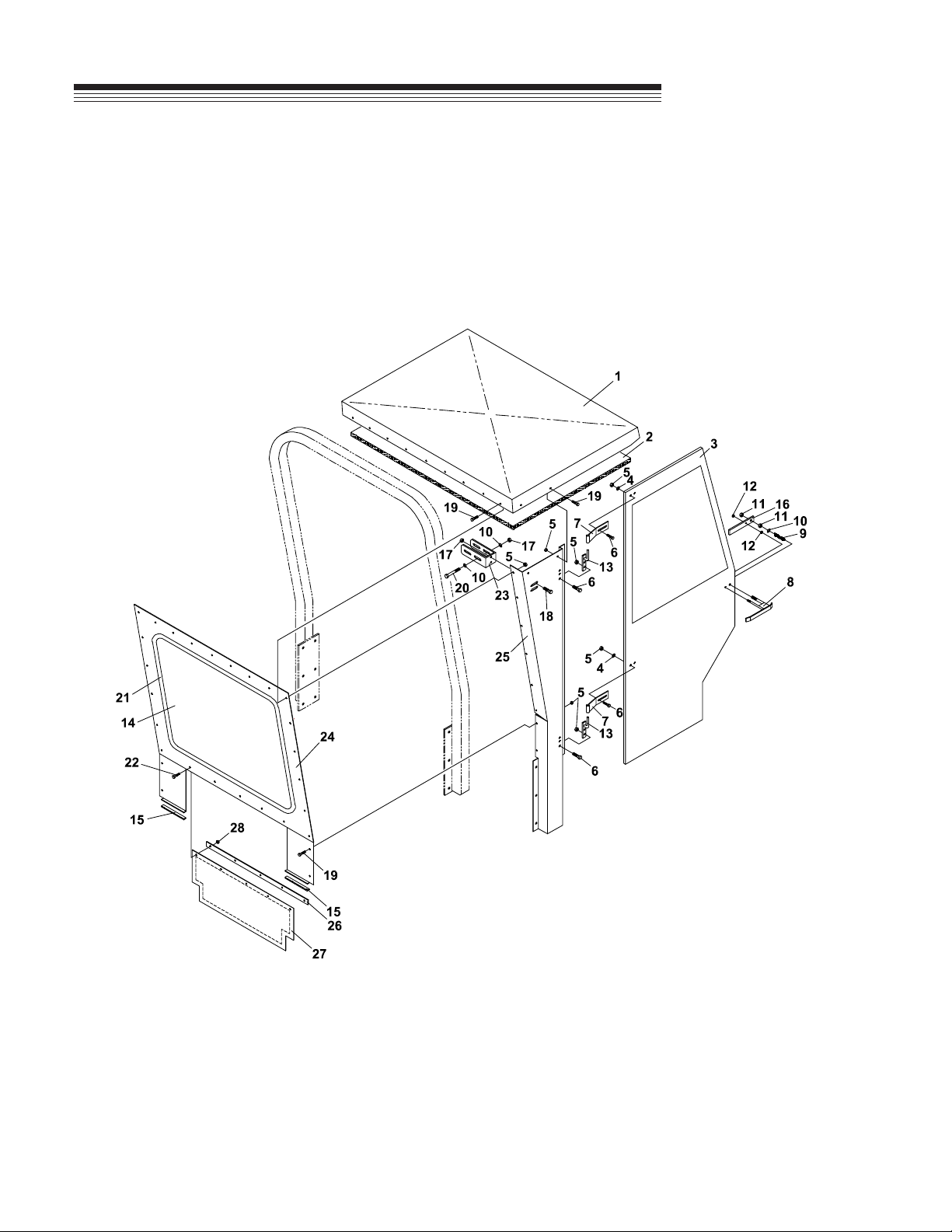
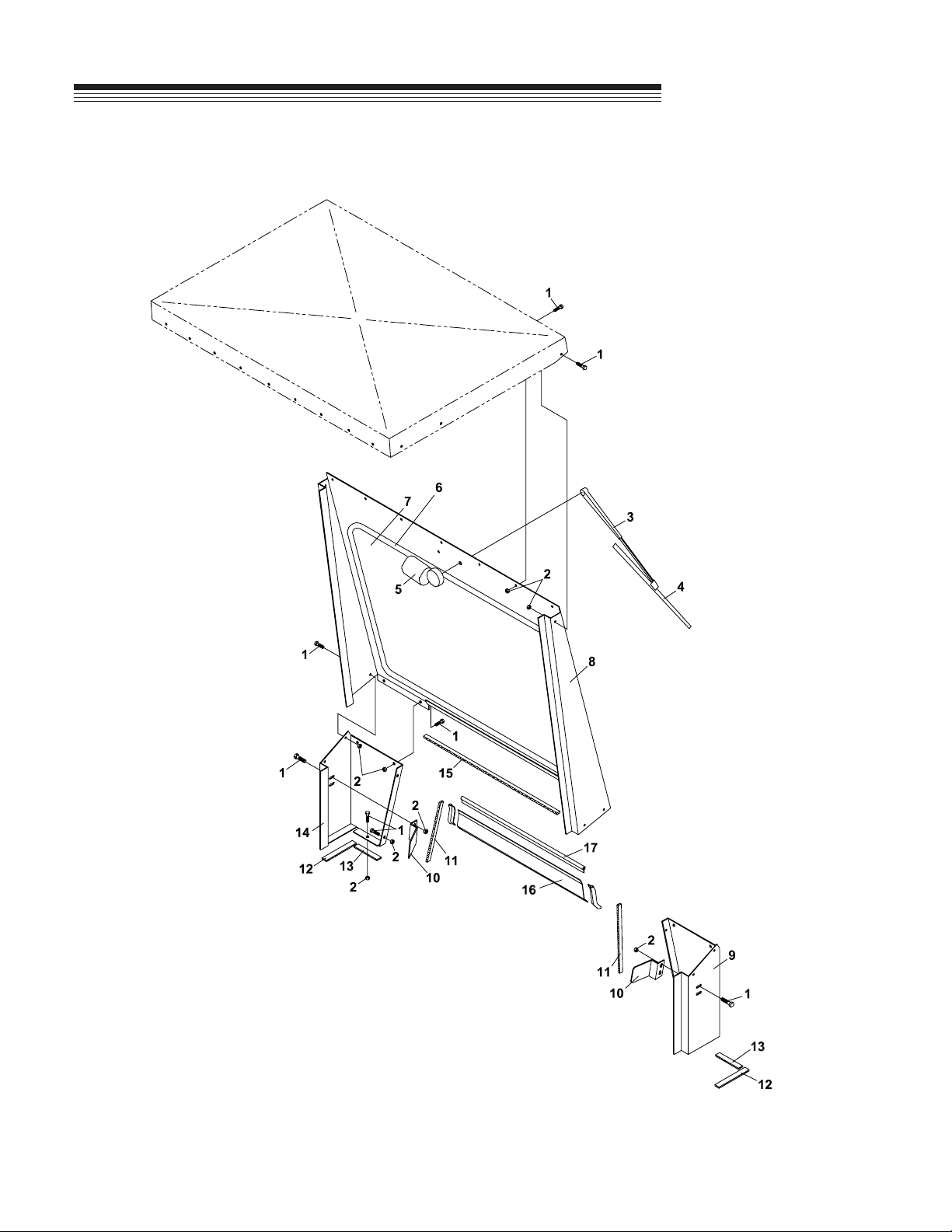
CAB PARTS (1)
FIGURE 1

17
TURF UNIT
CAB
ITEM PART NO. DESCRIPTION QTY ITEM PART NO. DESCRIPTION QTY
CAB PARTS (1)
FIGURE 1
1-1 62-666 ROOF PANEL 1
1-2 44-113 HEADLINER 1
1-3 4137033 DOOR-RIGHT 1
4137032 DOOR-LEFT 1
56-052-102 FOAM WEATHERSTRIP 102" 4
(USE 2 PER DOOR)
1-4 64163-55 WASHER .328X.75X14 8
1-5 64141-6 NUT, 5/16-18 42
1-6 64139-08 BOLT-5/16-18X3/4 16
1-7 64-580 DOOR HINGE 4
1-8 64-342 DOOR HANDLE-OUTSIDE 2
1-9 41-021 COMPRESSION SPRING 2
1-10 64163-61 WSHR .81X.406X16 10
1-11 64025-05 NUT-3/8-16 HEX 4
1-12 64025-01 NUT-1/4-20 HEX 4
1-13 64-340 DOOR HINGE PIN 4
1-14 06-036 REAR WINDSHIELD GLASS 1
1-15 56-052-06 FOAM STRIP-6" 2
1-16 64-566 LATCH-DOOR INSIDE HNDL 2
1-17 64141-4 NUT-WLF 3/8-16 8
1-18 64139-21 BLT-WLF 3/8-16X3/4 4
1-19 64139-13 BLT-WLF 5/16-18X1/2 26
1-20 64123-75 BOLT, 3/8-16X3 HEX 4
1-21 57-009-107 WINDSHIELD MOLDING-107" 1
1-22 64139-02 BLT-WLF 1/4-20X1/2 5
1-23 64-546 MOUNTING BRACKET 2
1-24 62-670 PANEL-REAR 1
1-25 62-668 SIDE PANEL-RIGHT 1
62-667 SIDE PANEL-LEFT 1
1-26 64-565 RETAINER STRAP-REAR 1
1-27 44-110 FABRIC PANEL-REAR 1
1-28 64141-2 NUT-WLF 1/4-20 5
18
TURF UNIT
CAB
CAB PARTS (2)
FIGURE 2
Table of contents


