AWE 3015-42201 User manual
Copyright 2022, AWE. No part of this document may be reused or duplicated without the express permission of AWE. All rights reserved. Rev 1.3
For up-to-date fitment information, please visit the product page on AWE-Tuning.com.
Welcome to the AWE family, and congratulations on your purchase of the AWE Exhaust System for the 4th Gen Chevy
Silverado 1500 5.3L and GMC Sierra 1500 5.3L.
Exquisite build quality and craftsmanship, coupled with industry leading performance, distinguish this exhaust system
from all others.
*For up to the minute fitment information, be sure to visit the AWE website. As always, AWE Performance Specialists
3015-42201 AWE 0FG Catback Split Rear Exit Exhaust for 4th Gen Silverado/Sierra 1500 5.3L (With Bumper Cut-
outs) - Quad Chrome Silver Tips
3015-43202 AWE 0FG Catback Split Rear Exit Exhaust for 4th Gen Silverado/Sierra 1500 5.3L (With Bumper Cut-
outs) - Quad Diamond Black Tips
3015-32205 AWE 0FG Catback Split Rear Exit Exhaust for 4th Gen Silverado/Sierra 1500 5.3L (Flat Bumper) -
Chrome Silver Tips
3015-33206 AWE 0FG Catback Split Rear Exit Exhaust for 4th Gen Silverado/Sierra 1500 5.3L (Flat Bumper) - Dia-
mond Black Tips
3015-22207 AWE 0FG Catback Single Side Exhaust for 4th Gen Silverado/Sierra 1500 5.3L (Flat Bumper) - Dual
Chrome Silver Tips
3015-23208 AWE 0FG Catback Single Side Exhaust for 4th Gen Silverado/Sierra 1500 5.3L (Flat Bumper) - Dual
Diamond Black Tips
REAR END SHOT, STRAIGHT ANGLE
Copyright 2022, AWE. No part of this document may be reused or duplicated without the express permission of AWE. All rights reserved. Rev 1.3
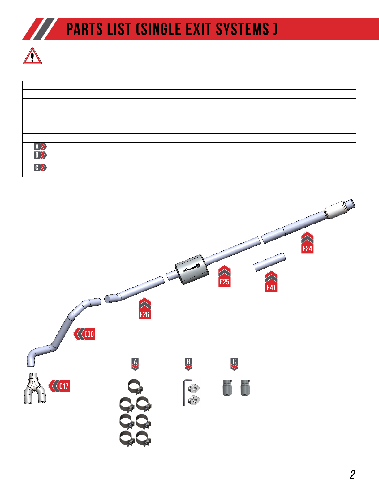
Inspect ALL parts prior to disassembly of vehicle; If damaged or MISSING,
please contact the place of purchase immediately.
Copyright 2020, AWE. No part of this document may be reused or duplicated without the express permission of AWE/Secor Ltd. All rights reserved. Rev1.1
Symbol Part Number Description QTY
E24 Silverado 4th Gen 5.3L Front Section w/ Flex 1
E25 Silverado 4th Gen 5.3L HR5 Section 1
E26 Silverado 4th Gen 5.3L Overaxle Inlet 1
E30 Silverado 4th Gen 5.3L Single Exit Tube 1
E41 Silverado 4th Gen 5.3L Long Wheel Base Adapter 1
C17 Universal 3" Inlet Dual 3" Outlet Rear Merge Assembly 1
180300 AWE Band Clamp: 3" 7
3910-11012 Clamp Kit 1
61000455 4.50" OD x 3.00" ID, Slash Cut, Chrome Silver 2
61000488 4.50” OD x 3.00” ID, Slash Cut, Diamond Black 2

Copyright 2022, AWE. No part of this document may be reused or duplicated without the express permission of AWE. All rights reserved. Rev 1.3
Inspect ALL parts prior to disassembly of vehicle; If damaged or MISSING,
please contact the place of purchase immediately.
Symbol Part Number Description QTY
E24 Silverado 4th Gen 5.3L Front Section w/ Flex 1
E25 Silverado 4th Gen 5.3L HR5 Section 1
E26 Silverado 4th Gen 5.3L Overaxle Inlet 1
E27 Silverado 4th Gen 5.3L Overaxle Tri Section 1
E31 Silverado 4th Gen 5.3L Driver Tailpipe w/o cutouts (Single 5") 1
E32 Silverado 4th Gen 5.3L Passenger Tailpipe w/o cutouts (Single 5") 1
E07 Silverado 4th Gen 5.3L DS/PS Rear Hanger 2
E41 Silverado 4th Gen 5.3L Long Wheel Base Adapter 1
180300 AWE Band Clamp: 3" 8
3910-11012 Clamp Kit 2
610400 Rubber Exhaust Isolater 2
180003BC 5" x 10", Straight Cut, Diamond Black Tip 2
180003 5”x10” Straight Cut Chrome Silver Tip 2

Copyright 2022, AWE. No part of this document may be reused or duplicated without the express permission of AWE. All rights reserved. Rev 1.3
Inspect ALL parts prior to disassembly of vehicle; If damaged or MISSING,
please contact the place of purchase immediately.
Symbol Part Number Description QTY
E24 Silverado 4th Gen 5.3L Front Section w/ Flex 1
E25 Silverado 4th Gen 5.3L HR5 Section 1
E26 Silverado 4th Gen 5.3L Overaxle Inlet 1
E27 Silverado 4th Gen 5.3L Overaxle Tri Section 1
E28 Silverado 4th Gen 5.3L Driver Tailpipe w/cutouts (Quad 102) 1
E29 Silverado 4th Gen 5.3L Passenger Tailpipe w/cutouts (Quad 102) 1
E33 Silverado 4th Gen 5.3L/6.2L Tip Outlet (Quad 102 Outlet) 2
E41 Silverado 4th Gen 5.3L Long Wheel Base Adapter 1
SEC75 3" Barrel Clamp (Bubble) 2
180300 AWE Band Clamp: 3" 6
3910-11012 Clamp Kit 1
180010 4.00" OD x 2.50" ID, Slash Cut, Chrome Silver, AWE Logo 4
180011 4.00" OD x 2.50" ID, Slash Cut, Diamond Black, AWE Tuning 4
Copyright 2022, AWE. No part of this document may be reused or duplicated without the express permission of AWE. All rights reserved. Rev 1.3
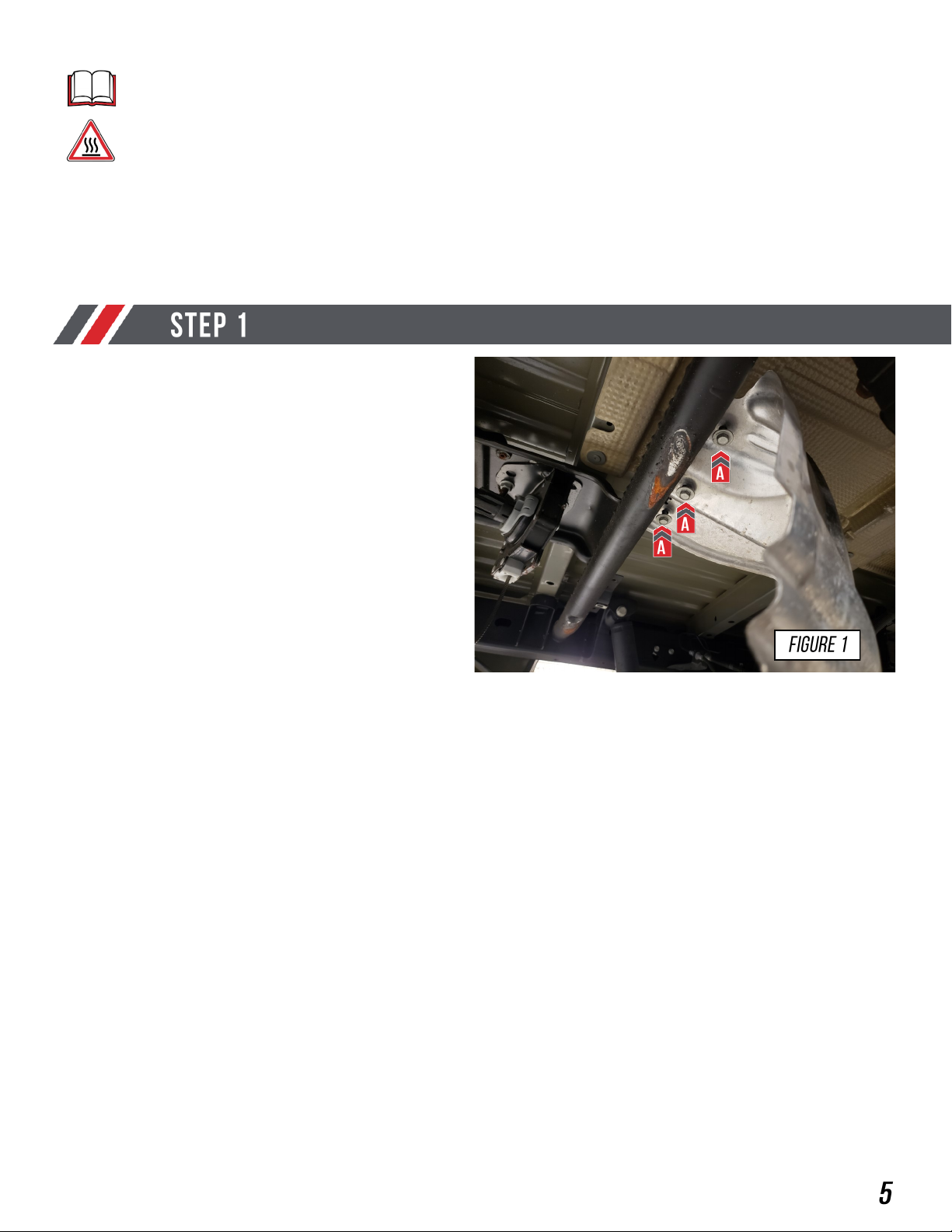
NOTE: Always refer to the manufacturer’s service manual for precise torque specifications
on all OEM fasteners.
CAUTION: The exhaust may be VERY HOT — allow adequate time for the system to cool
down before disassembly. Severe burns and injury will occur if skin comes into contact with
a hot exhaust system.
Begin removing your OE exhaust system by first
removing your spare tire.
Next remove the OE heat shield, and hardware
shown in Figure 1 at (A).
Note: This will be reinstalled after you remove
the OE exhaust

Copyright 2022, AWE. No part of this document may be reused or duplicated without the express permission of AWE. All rights reserved. Rev 1.3
1. To begin you will loosen the OE ball socket
clamp, shown at (A), enough to separate the
two components.
2. Remove the 3 OE hangers from the exhaust
shown at (B).
3. With the OE exhaust no longer attached to
the vehicle, remove the complete exhaust.
Note: The factory clamp will be used with your
AWE exhaust.
Note: After the OE exhaust is completely
removed, re-install the OE heat shield,
and the spare tire.
Soak all bolts and rubber hangers in
penetrating oil before starting any work.
OE SINGLE SIDE EXIT REMOVAL
Start by removing the OE single exit
exhaust by following the steps, shown in
Figure 2A.
Copyright 2022, AWE. No part of this document may be reused or duplicated without the express permission of AWE. All rights reserved. Rev 1.3
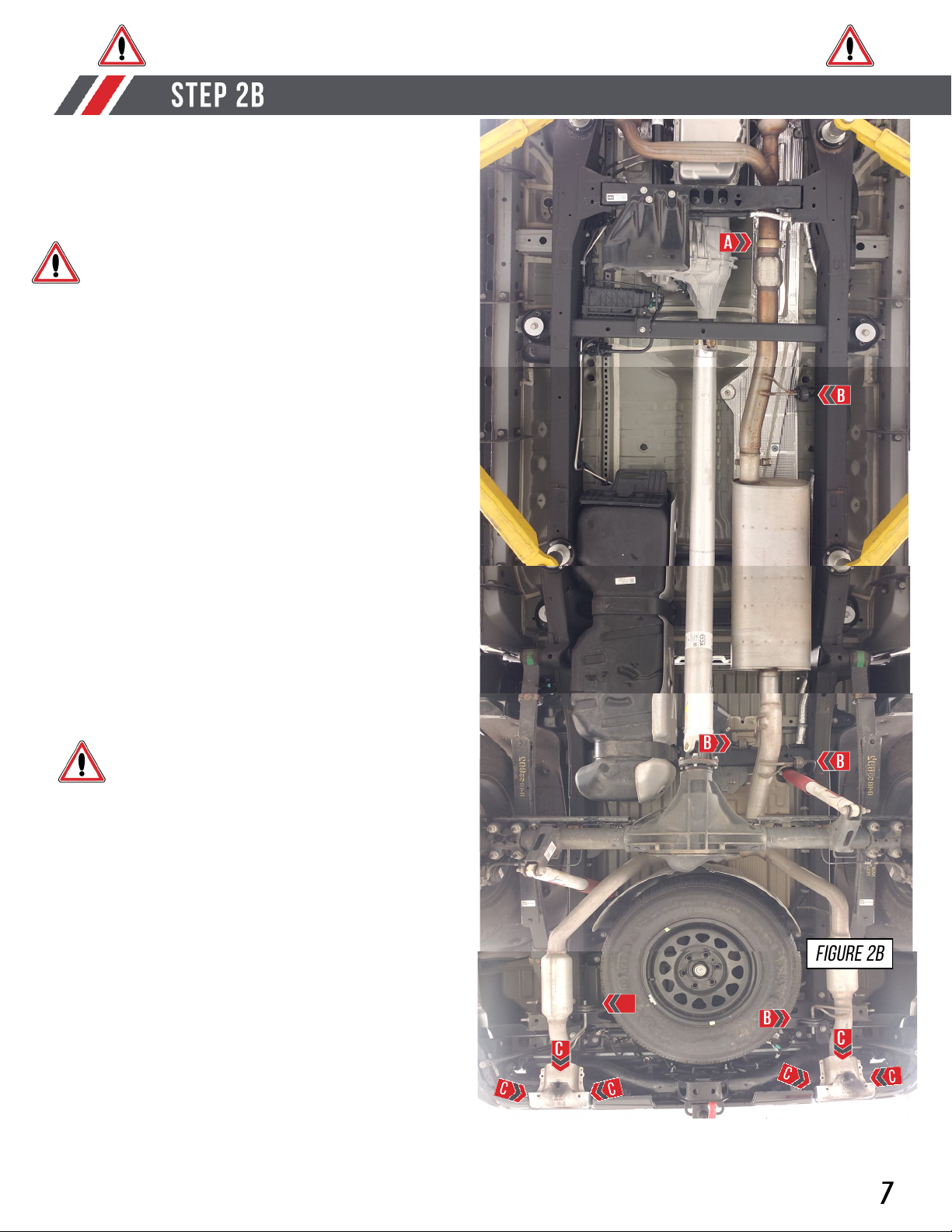
OE DUAL REAR EXIT EXHAUST REMOVAL
1. To begin you will loosen the OE ball socket
clamp, shown at (A), enough to separate the
two components.
2. Remove the 5 OE hangers from the exhaust
shown at (B).
3. With the OE exhaust no longer attached to
the vehicle, remove the complete exhaust.
4. Remove the OE tip bezels by removing the
3 bolts per side marked at (C). On each
bezel, all 3 bolts are located on the top side.
Note: The factory clamp will be used with your
AWE exhaust.
Note: The OE tip bezels will not be reused.
Note: After the OE exhaust is completely
removed, re-install the OE heat shield,
and the spare tire.
Soak all bolts and rubber hangers in
penetrating oil before starting any work.
Start by removing the OE dual exit
exhaust by following the steps, shown in
Figure 2B.
Copyright 2022, AWE. No part of this document may be reused or duplicated without the express permission of AWE. All rights reserved. Rev 1.3
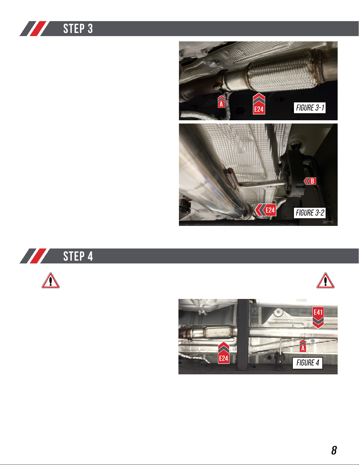
Insert the ball flange on your AWE front section
over the factory flared pipe, as shown at (A) in
Figure 3-1. Slide the OE clamp onto your AWE
inlet section (E24).
Slide the hanger bar into the OE hanger as
shown at (B) in Figure 3-2. Snug the clamp but
do not fully tighten it.
If you have a long wheel base truck install your
AWE long wheel base adapter (E41) after the
AWE inlet section (E24). Slide a provided
clamp on the adapter (E41), as shown at (A) in
Figure 4. Snug the clamp but do not fully
tighten it
STEP 4 IS FOR LONG WHEEL BASE VEHICLES ONLY

Copyright 2022, AWE. No part of this document may be reused or duplicated without the express permission of AWE. All rights reserved. Rev 1.3
Slide one of the provided exhaust clamps onto
the end of the pipe (A). Then install your AWE
HR5 section (E25), as shown in Figure 5.
Note: Snug the clamp but do not fully tighten it
at this point.
Place a provided exhaust clamp over the
expanded end of your AWE overaxle inlet tube
(E26), shown at (A) in Figure 6.
Bottom the slip fit on the HR5 section (E25).
When the tube is bottomed out slide the hanger
bars into the hangers as shown at (B) in
Figure 6.
Note: Snug the clamp down but do not tighten
it fully at this time.
Copyright 2022, AWE. No part of this document may be reused or duplicated without the express permission of AWE. All rights reserved. Rev 1.3
IF INSTALLING THE DUAL EXIT EXHAUST SYSTEM, SKIP TO STEP 14
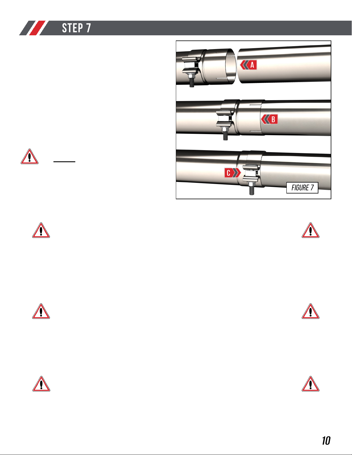
It is crucial to install each section and exhaust
band clamps correctly to prevent loose joints,
exhaust leaks and rattles.
Arrow A shows the expanded pipe and the
preinstalled exhaust clamp being brought up to
the corresponding pipe.
Arrow B shows the overlapping pipe installed
correctly over the corresponding pipe.
Arrow C shows the exhaust band clamp being
brought to the edge of the expanded pipe.
NOTES:
• Do not fully torque any exhaust
clamp until the entire exhaust has
been installed and adjusted.
• Torque specification is a minimum of
60 ft/lbs
IF INSTALLING THE QUAD TIP EXHAUST SYSTEM, SKIP TO STEP 21
IF INSTALLING THE SINGLE EXIT EXHAUST SYSTEM, SKIP TO STEP 8
This manual suits for next models
5
Other AWE Automobile Accessories manuals


Popular Automobile Accessories manuals by other brands


ULTIMATE SPEED
ULTIMATE SPEED 279746 Assembly and Safety Advice

SSV Works
SSV Works DF-F65 manual

ULTIMATE SPEED
ULTIMATE SPEED CARBON Assembly and Safety Advice

Witter
Witter F174 Fitting instructions

WeatherTech
WeatherTech No-Drill installation instructions

TAUBENREUTHER
TAUBENREUTHER 1-336050 Installation instruction