Wynn's Aircomatic III Operating instructions

Repair manual Aircomatic III
Status: Accepted
Revision: 3
Date: 31-8-2011

2
Table of Contents
1. Broken or noisy fan ......................................................................................................................... 3
2. Replacing transducer....................................................................................................................... 5
3. Damaged powercable...................................................................................................................... 6
4. Replacing the filter .......................................................................................................................... 7
5. No ozone production....................................................................................................................... 8
6. Pressure calibration......................................................................................................................... 9
Appendix A. How to open the Aircomatic III......................................................................................... 10
Appendix B. How to close the Aircomatic III ......................................................................................... 12

3
1. Broken or noisy fan
Step 1. Open the Aircomatic III as described in Appendix A.
Step 2. Remove the two cables that are connected via a green connector; and the ozonebox.
Step 3. Remove 3 nuts to remove the board. Be careful that the blue hose remains connected !

4
Step 4. Desolder fan wires
Step 5. Remove nuts from fan
Step 6. Replace fan, and put screws back.
Step 7. Solder wires back, notice + and –
Step 8. Put board back and test the fan.
Step 9. Close the Aircomatic as described in Appendix B.

5
2. Replacing transducer
Step 1. Open the Aircomatic III as described in Appendix A.
Step 2. Remove nuts from transducerholder and remove holder.
Step 3. Before removing the transducer, notice how the rubber ring is placed in the holder. Remove
the transducer by removing the rubber ring.
Step 4. Remove the new transducer from its transducer holder and place it in the holder
Step 5. Put nuts back and fasten them with a force of 2 Newton.
Step 6. Test the device by using 60ml of water and check that it produces mist.
Step 7. Close the Aircomatic as described in Appendix B.
NOTE:
If the amount of mist produced is very low it might be necessary to
adjust the control of the transducer. This is possible by adjusting
the small potentiometer on the board until there is a maximum
amount of mist produced.

6
3. Damaged powercable
Step 1. Open the Aircomatic III as described in Appendix A.
Step 2. Remove powersupply connector from board
Step 3. Remove two nuts and replace board, make sure that there is just enough room to fit the
other shell. Too much room will cause the pressure inside the device drop during operation.
Step 4. Reconnect powersupply board to mainboard and close the Aircomatic III as described in
Appendix B.

7
4. Replacing the filter
Replacing the filter is simple pulling out the old one and replacing it by a new one. A screwdriver can
be helpful in getting the filter out. Please note the way it is inserted.

8
5. No ozone production
If no ozone is produced either the ‘ozonebox’ can be faulty or the board. Start by replacing the
‘ozonebox’, if this does not solve the problem replace the board.
Replacing the board is already described in chapter 1. Please note, when the board is actually
removed the blue hose must NOT be removed from the board, but on the side of the bottle. The
hose is connected to a black hoseconnector, to release the hose connector press on the connector
inwards and gently pull on the blue hose.
Finally make sure you calibrate the Aircomatic III as described in chapter 6.

9
6. Pressure calibration
The level of the liquid is measured by measuring the pressure it causes compared to the to the
outside pressure. The pressure sensor can only operate if it is correctly calibrated. This means it
needs to be zero when the Aircomatic III is not filled with liquid. If there is any liquid in the
measurement tube, the Aircomatic will not read the actual pressure, this can cause it to stop too
early or too late.
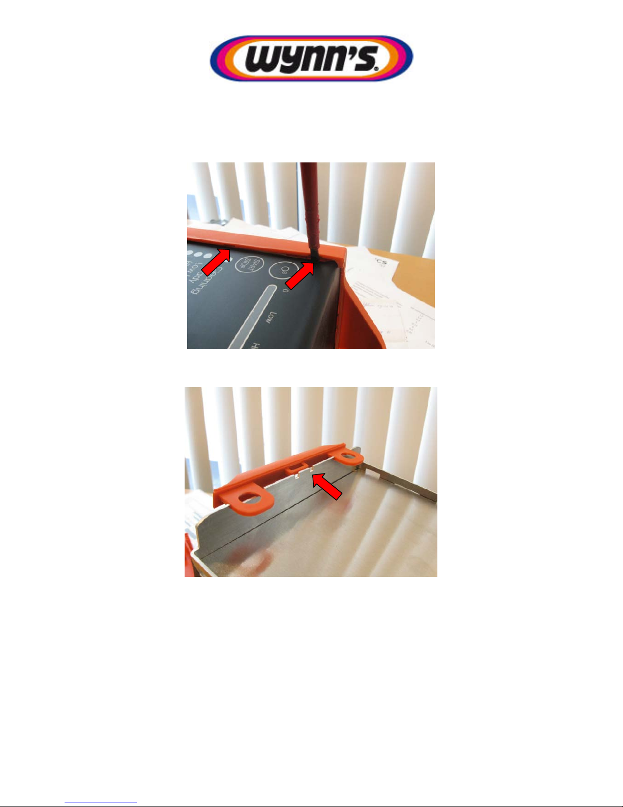
To help check this the blue led bar can be used. To check the level, press-and-release the ‘O3’ button
until the blue bar is half full (this way you see when it displays the pressure). Now press-and-hold the
‘O3’ button for 10-15 seconds. The display will start displaying the measured pressure.
Each LED represents a certain value, with LED 8 indicating positive of negative pressure. The pressure
is acceptable when the following combinations are visible:
LED1 LED2 LED3-7 LED8
OFF OFF OFF Don’t care
ON OFF OFF Don’t care
OFF ON OFF Don’t care
All other values indicate that pressure is too high or too low
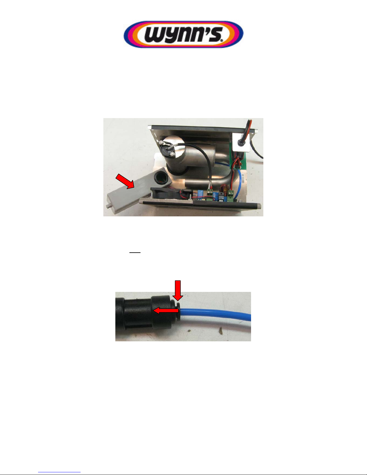
Before zeroing the pressure measurement you need to be sure that no liquid is in the measurement
tube. This can be checked by simply enabling this indication and shaking the product up-and-down,
and even upside down. If any liquid is present in the tube you should see the indication vary.
Once, the reading is stable this can be considered zero. By pressing-and-holding ‘Start/Stop’ button
for around 10 seconds the device is reset. The ‘High’ and ‘Low’ LEDs will blink, when the blue
‘Cleaning’ LED also blinks calibration has been performed successfully.
LED1
LED8

10
Appendix A. How to open the Aircomatic III
Step 1. By using a flat screwdriver carefully pushback the side panel, there are 3 slots on each side.
Step 2. Once one side has been lifted the other side slides off easily.
Step 3. Remove the handle, by lifting the it from it lock-position

11
Step 4. Finally remove the bottom shell by pushing open both back and front panel and pulling the
bottom shell. The inside will now be visible.

12
Appendix B. How to close the Aircomatic III
Step 1. Put back the bottom shell. Do this by first sliding in the part with the cutout into the top shell.
Step 2. Press on the top of the shell to push it into the other shell, please not, make sure that you
align the ozonebox with the hole

13
Step 3. Push-in or pull-out the side panels till they slide into their slots.
Step 4. Put handle back
Step 5. Put side panels back:
1. Centre the side panel with the handle
2. Push on the corners in the designated order.
1
2
3
4
Other manuals for Aircomatic III
1
Table of contents
Popular Automobile Accessories manuals by other brands

DV8 OFFROAD
DV8 OFFROAD MPGX-02 installation manual

Volkswagen
Volkswagen 5G9 061 197 A installation instructions

Stromberg Carlson Products
Stromberg Carlson Products BC-104 manual

Thule
Thule 1612 instructions

Rhino-Rack
Rhino-Rack Rhino Sportz SQRS instruction manual

Mountain Top
Mountain Top CCS FO10 0B01 installation manual