Steiner TR270 TERRA Programming manual
OPERATOR’S & PARTS MANUAL
MAN 4177521
Rev. A 04-2019
75-70681
TR270 TERRA RAKE
(S/N 0000 and higher)

2
TERRA
RAKE
IMPORTANT MESSAGE
Thank you for purchasing this Schiller Grounds Care, Inc. product. You have purchased a world class product,
one of the best designed and built anywhere.
This product comes with an Operator's/Parts Manual. The useful life and good service you receive from this
product depends to a large extent on how well you read and understand this manual. Treat this product
properly and adjust it as instructed, and it will give you many years of reliable service.
See a Schiller Grounds Care, Inc. dealer for any service or parts needed. Schiller Grounds Care, Inc. service
ensures that you continue to receive the best results possible from Schiller Grounds Care, Inc. products. You
can trust Schiller Grounds Care, Inc. replacement parts because they are manufactured with the same high
precision and quality as the original parts.
Schiller Grounds Care, Inc. designs and builds its equipment to serve many years in a safe and productive
manner. For longest life, use this product only as directed in the manual, keep it in good repair and follow
safety warnings and instructions. You'll always be glad you did.
Schiller Grounds Care, Inc.
One Bob Cat Lane
Johnson Creek, WI 53038-0469
CALIFORNIA PROPOSITION 65
WARNING: Cancer and Reproductive Harm - www.P65Warnings.ca.gov.
ADVERTENCIA: Cáncer y Dãno Reproductivo - www.65Warnings.ca.gov.
TABLE OF CONTENTS .................................................FIGURES ......................................................... PAGE
TABLE OF CONTENTS.................................................. ................................................................................ 2
DESCRIPTION / SPECIFICATIONS ................................................................................................................ 3
SAFETY ........................................................................................................................................................4-6
ASSEMBLY / OPERATION............................................................................................................................... 7
OPERATION..................................................................................................................................................... 8
TINE DEPTH / TINE ANGLE ADJUSTMENT ................................................................................................... 9
ROTATION ADJUSTMENT / CASTER ARM PLACEMENT ........................................................................... 10
OPTIONAL 3-POINT HITCH MOUNTING ............................................................................................... 11, 12
MAINTENANCE / STORAGE......................................................................................................................... 13
PARTS SECTION........................................................... .............................................................................. 15
HITCH ASSEMBLY.........................................................FIGURE 1......................................................... 16, 17
MAIN FRAME ASSEMBLY .............................................FIGURE 2......................................................... 18, 19
CASTER WHEEL ASSEMBLY .......................................FIGURE 3......................................................... 20, 21
TINE ASSEMBLY ...........................................................FIGURE 4......................................................... 22, 23
TABLE OF CONTENTS

3
TERRA
RAKE
04-2019
DESCRIPTION / SPECIFICATIONS
DESCRIPTION
The front mounted Steiner landscape rake, the TR270 Terra Rake, effectively rakes soil, landscape debris,
aggregate and other materials. Applications include seed bed preparation, or landscape work such as leveling
dirt or gravel in driveways and parking areas.
From the operator's seat, the accessory controls on the Steiner tractor are used to hydraulically angle the
70" wide rake left or right to direct raked material. A spring-tensioned leveling system in combination with the
independently height adjustable caster wheels provides material leveling independent of the tractor. The Terra
Rake tine angle and tine depth can be easily adjusted from aggressive, to move large amounts of material,
to light, to nely nish the surface with a reduced potential of unwanted throwing of debris. The caster wheels
can be mounted inward to the front when working near structures, outward for greater leveling control, or to
the rear of the rake, giving operators maximum exibility.
The TR270 Terra Rake comes with the Steiner Quick Hitch attachment system for easy installation or removal
in minutes without any tools. The Terra Rake can also be mounted to the rear 3-point hitch with a Steiner
3-Point Quick Hitch.
SPECIFICATIONS
Specications are subject to change without notice.
Overall Length with Wheels in front................................. 65"
Overall Length with Wheels in rear.................................. 48"
Overall Height.................................................................. 30"
Maximum working width .................................................. 70"
Minimum working width (angled)..................................... 65"
Right and left maximum angle......................................... 20°
Number of tines ............................................................... 40
Tine adjustment range..................................................... 4.25" below grade
......................................................................................... 4.50" above grade
Rake angle adjustment.................................................... ±5°
Caster wheel height adjustment ...................................... 4.75"
Weight ............................................................................. 382 lbs.
4
TERRA
RAKE
SAFETY
NOTICE !!!
Unauthorized modications may present extreme
safety hazards to operators and bystanders and
could also result in product damage.
Schiller Grounds Care, Inc., strongly warns against,
rejects and disclaims any modications, add-on
accessories or product alterations that are not
designed, developed, tested and approved by Schiller
Grounds Care, Inc. Engineering Department. Any
Schiller Grounds Care, Inc. product that is altered,
modied or changed in any manner not specically
authorized after original manufacture–including the
addition of “aftermarket” accessories or component
parts not specically approved by Schiller Grounds
Care, Inc.–will result in the Schiller Grounds Care,
Inc. Warranty being voided.
Any and all liability for personal injury and/or property
damage caused by any unauthorized modications,
add-on accessories or products not approved by
Schiller Grounds Care, Inc. will be considered
the responsibility of the individual(s) or company
designing and/or making such changes. Schiller
Grounds Care, Inc. will vigorously pursue full
indemnication and costs from any party responsible
for such unauthorized post-manufacture modications
and/or accessories should personal injury and/or
property damage result.
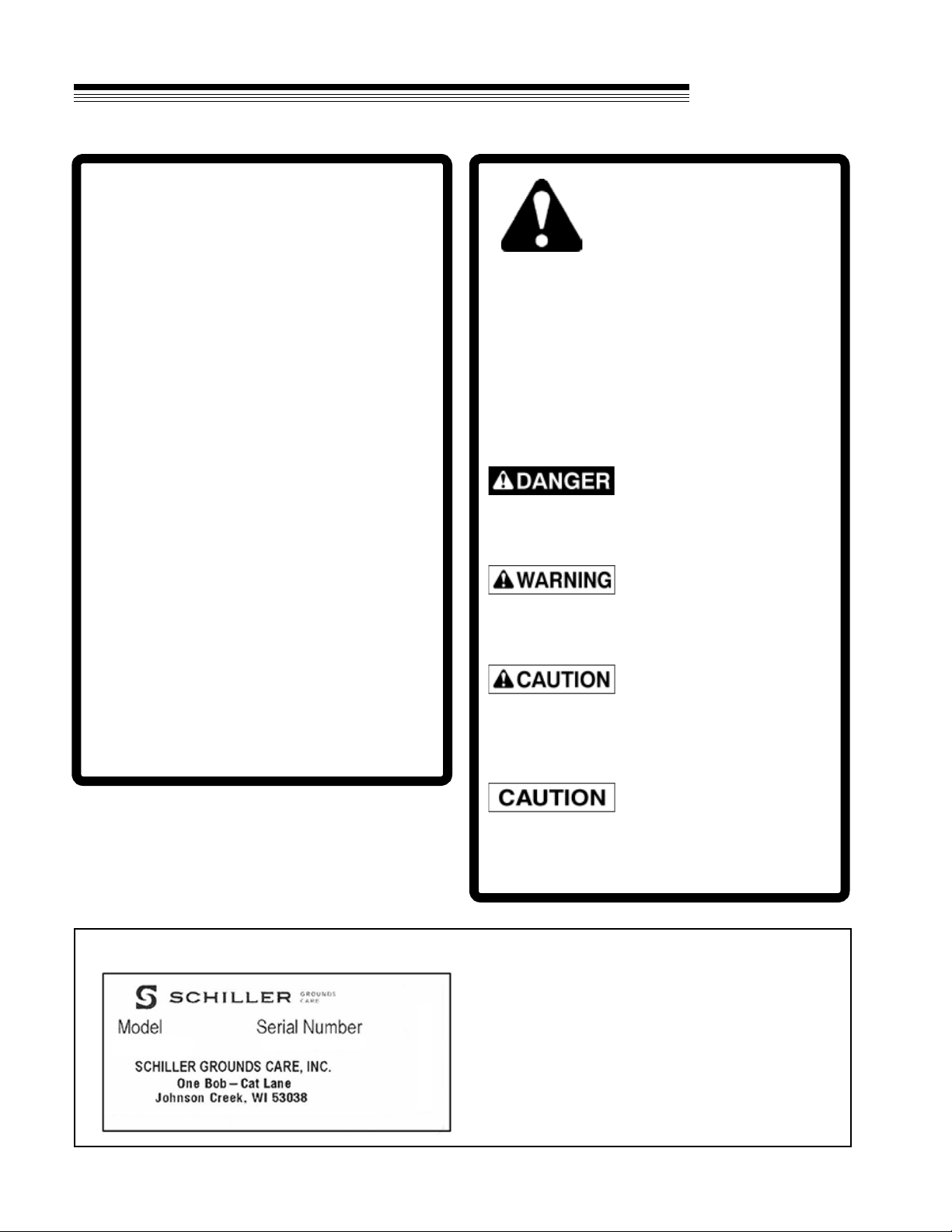
MODEL NUMBER: This number appears on
sales literature, technical manuals and price lists.
SERIAL NUMBER: This number appears only
on your tractor. It contains the model number
followed consecutively by the serial number.
Use this number when ordering parts or seeking
warranty information.
This symbol means:
ATTENTION!
BECOME ALERT!
Your safety and the safety of others is involved.
Signal word denitions:
The signal words below are used to identify levels
of hazard seriousness. These words appear in this
manual and on the safety labels attached to Schiller
Grounds Care, Inc. machines. For your safety and
the safety of others, read and follow the information
given with these signal words and/or the symbol
shown above.
DANGER indicates an imminently hazardous
situation which, if not avoided, WILL result in death
or serious injury.
WARNING indicates a potentially hazardous
situation which, if not avoided, COULD result in
death or serious injury.
CAUTION indicates a potentially hazardous situation
which, if not avoided, MAY result in minor or moderate
injury. It may also be used to alert against unsafe
practices or property damage.
CAUTION used without the safety alert symbol
indicates a potentially hazardous situation which, if
not avoided, MAY result in property damage

5
TERRA
RAKE
SAFETY
GENERAL SAFETY
Read the Operation & Safety Manual
• The owner of this machine is solely responsible for properly training the operators.
• The owner/operator is solely responsible for the operation of this machine and prevention of accidents or
injuries occurring to him/herself, other people, or property.
• Read and understand the operator’s manual, before attempting to operate this machine.
• Operate all controls from the operator’s seat.
• If the operator of the machine cannot understand this manual, then it is the responsibility of this machine’s
owner to fully explain the material within this manual to the operator.
• Learn and understand the use of all controls.
• Know how to stop the power unit and all attachments quickly in the event of an emergency.
• Do not leave machine unattended while it is running. STOP the engine and remove the key, set parking
brake and lower attachment.
• Always park the machine on level ground.
• Do not allow minors, untrained personnel or the inexperienced to operate this machine.
• Children are attracted to machine activity. Be aware of children and do not allow them in the working area.
Turn off the machine if a child enters the work area.
• Do not operate or repair machine if you are not in good physical and mental health, if you will be
distracted by personal devices, or are under the inuence of any substance which might impair deci sion,
dexterity, or judgment.
• Keep people and pets a safe distance away while using this machine. Injury could result from ying
debris. Stop machine if someone enters the work area.
• Wear protective clothing and personal safety devices to protect your head, eyes, ears, hands, and feet.
• Always be alert to what is happening around you, but do not lose focus on the task you are performing.
• Always look in the direction the machine is moving.
• Stop operation immediately at any sign of equipment failure. An unusual noise or vibration can be a
warning of equipment failure or a sign that maintenance is required. Make all necessary repairs before
operating machine again.
• Only operate in well-lit conditions.

6
TERRA
RAKE
SAFETY / SAFETY DECALS
OPERATION SAFETY
• Do not attempt to work on the Terra Rake while the power unit engine is running.
• Inspect machine before operation. Repair or replace any damaged, worn, or missing parts. Be sure
guards and shields are in proper working condition and are secured in place. Make all necessary
adjustments before operating machine.
• Alterations or modications to this machine can reduce safety and could cause damage to the machine.
• Before each use, verify that all controls function properly and inspect all safety devices. Do not operate if
controls or safety devices are not in proper working condition.
• Make sure all hydraulic connections are tight and all hydraulic hoses and tubes are in good condition.
Repair any leaks and replace any damaged or deteriorated hoses or tubes before starting the machine.
• Hydraulic leaks can occur under high pressure. Hydraulic leaks require special care and attention. Use
a piece of cardboard and a magnifying glass to locate suspected hydraulic leaks. Keep body and hands
away from pinhole leaks or nozzles that eject high pressure hydraulic uid. Hydraulic uid escaping
under high pressure can penetrate the skin causing serious injury, leading to severe complications and/
or secondary infections if left untreated. If hydraulic uid is injected into the skin, seek immediate medical
attention
• The Terra Rake hydraulic system may contain stored energy. Before performing maintenance or repairs
on the attachment, lower attachment to the ground, shut off power unit engine, put hydraulic accessory
lever in oat to relieve hydraulic pressure, and disconnect hydraulic hoses from the auxiliary quick
connectors.
• Ensure the Terra Rake is fastened securely to the power unit before operating.
• Never leave the operator’s seat without lowering the attachment to the ground, setting the parking
brake, shutting off the engine, and removing the ignition key. Make sure all moving parts have come to a
complete stop before dismounting.
• Do not attempt to straighten bent tines. Bending a tine may cause it to break.
• Do not use the TR270 for digging or moving large amounts of material. The TR270 is designed for
nishing work. Overly aggressive contact with the ground, aggregate, rocks, and other debris can cause
damage to the Terra Rank including bent or broken tines.
• Know the work area well before operation. Do not operate where traction or stability is questionable.
7
TERRA
RAKE
ASSEMBLY
ASSEMBLY
1. On level ground, remove rake and attaching
parts from shipping crate.
2. Attach Hitch Frame to Main Frame with eight 3/8-
16 X 1 bolts Aand eight 3/8-16 nuts Bas shown.
3. Lower kickstand. Adjust to desired height.
4. Attach caster arms to desired location. See
Caster Arm Placement Section for information
regarding caster arm location.
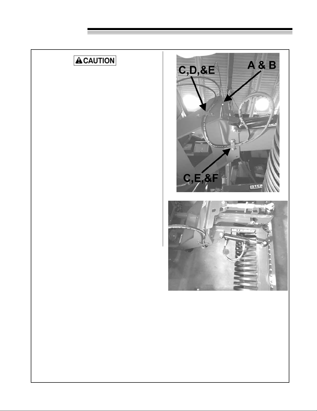
5. Route hoses and install hose clamp Cto main
frame using two 5/16-18x1-1/4 bolts F and two
5/16-18 nuts E. Install hose clamp Cto hitch
frame using two 5/16-18 x 1 bolts Dand two
5/16-18 nuts E.Be sure to provide enough slack
to allow full motion of hitch arms while not pulling
hoses too tight.
6. Grease center ball joint and caster wheels.
Attaching to Tractor
7. Operate latch control lever on tractor to open
hitch latches.
8. Drive tractor into position aligning the quick hitch.
9. Engage both latches and conrm they are in the
locked position.
10. Lower, set parking brake, turn off tractor.
11. Wipe hose ends clean and attach hydraulic
hoses to auxiliary quick connect ports on power
unit.
12. Raise kickstand.
13. Check and tighten all bolts. Grease center ball
joints and caster wheels.
Rear Weight Requirements
• The Steiner 450 tractors requires two 50#
rear weights based upon average raking
conditions and operator’s weight of 150 lbs. The
recommendations may vary with the weight of
the operator, other accessories, and operating
conditions. It is the operator’s responsibility to
determine the correct amount of weight needed
to improve stability. All weights must be removed
when the rake is removed.
• If equipped with a cab, no weights are required.
NOTE: Optional 3-point hitch installation is covered
under it own section. See 3-Point Hitch Installation
Section.

8
TERRA
RAKE
OPERATION
1. Set tine depth and angle for desired surface nish. See Angle Adjustment and Tine Depth Adjustment
Sections.
2. Use hydraulic angle adjustment to rotate rake left or right.
3. Transport with the rake raised to prevent tines from catching on high spots, rocks, debris, or other
obstacles.
4. Operate in "FLOAT" to allow the rake to follow terrain and level independently of tractor.
5. Remove large rocks before raking. DO NOT use the Terra Rake as a bulldozer. If large amounts of
material needs to be leveled, start with a Steiner Slip Scoop or Steiner Power Angle Blade and smooth
out rst. Finish with the Terra Rake.
Detaching from Tractor
1. Park power unit on level surface and set the parking brake.
2. Lower kickstand and lower rake to the ground. Shut off the tractor.
3. Disconnect the hydraulic hoses from the tractor and store with the hose ends on rake. Do not allow hose
ends to lay on the ground.
4. Disengage the front hitch latches.
5. Restart unit, release the parking brake and slowly back away from the rake.
OPERATION
9
TERRA
RAKE
TINE DEPTH AND TINE ANGLE ADJUSTMENT
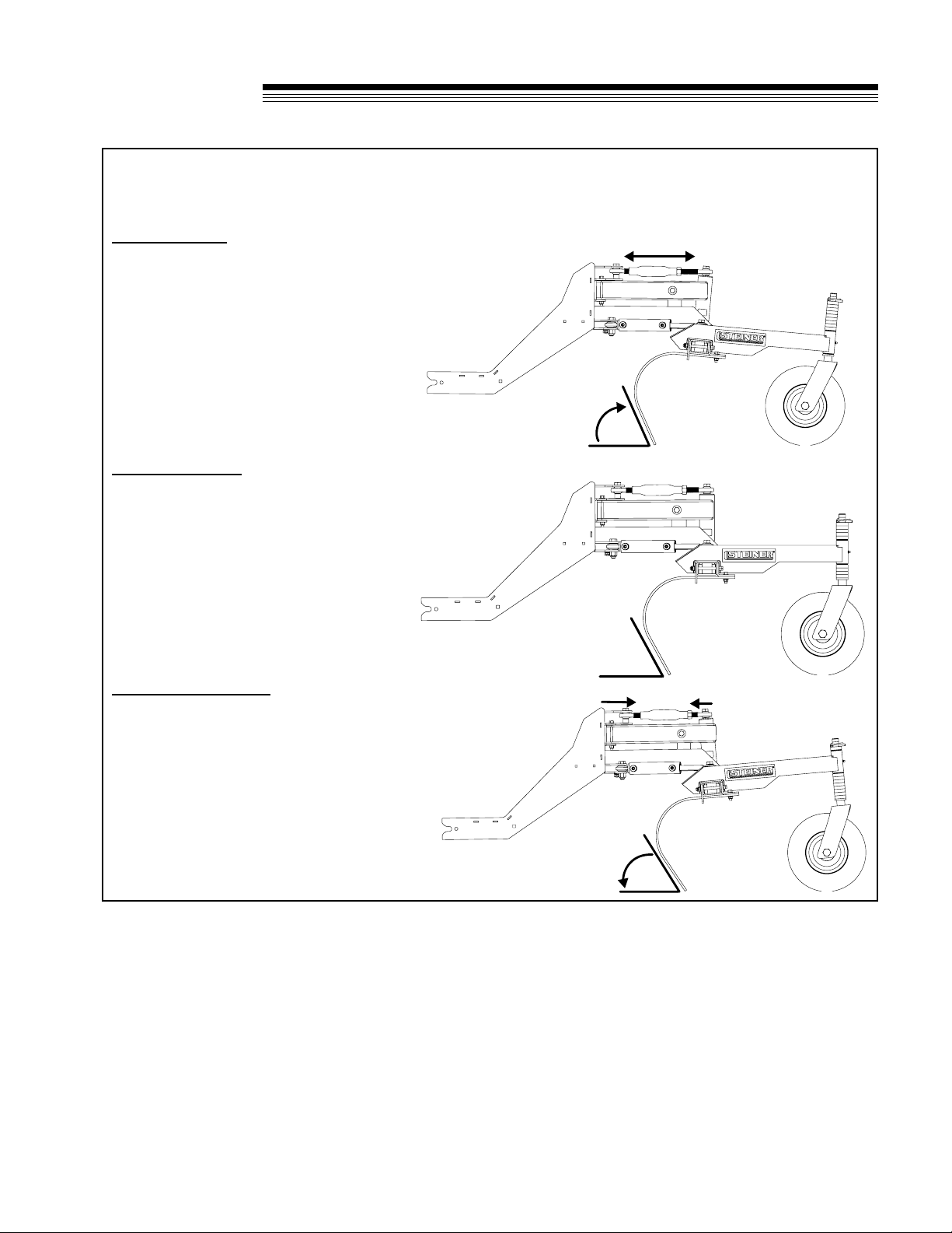
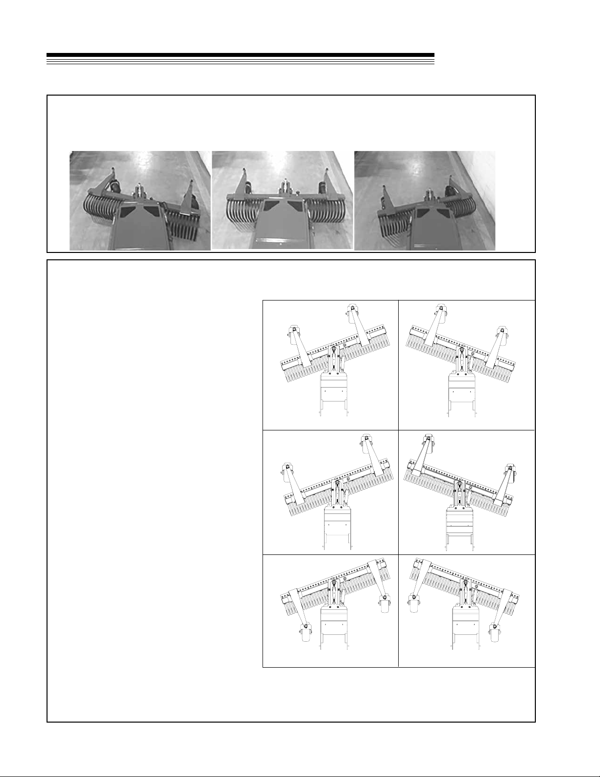
The TR270 tine depth and tine angle can be set to desired depths and angles by adjusting the caster spacer
positions and the top link length. See typical congurations below.
Light Tine Angle
• Light tine angles are useful for lightly
combing loose material to nish, clean or
prep a work site.
• Increasing the length of the top link will
lighten the effectiveness of the tine angle
and also decreases the tine depth.
• To maintain desired tine depth, caster
spacers need to be repositioned from
below the caster arm to above the caster
arm.
Neutral Tine Angle
• Neutral tine angle produces the most
satisfactory results across most working
conditions.
• Neutral tine angle position is achieved by
adjusting the top link until the top of the
caster arms are running parallel with the
ground.
• Caster spacer positions may also need
to be adjusted to achieve a neutral tine
angle at desired depth.
Aggressive Tine Angle
• Aggressive tine angles are useful for
moving large amounts of material and
working heavily compacted materials.
• Decreasing the length of the top link will
increase the aggressiveness of the tine
angle and also increase the tine depth.
• To maintain desired tine depth, caster
spacers need to be repositioned from
above the caster arm to below the caster
arm.
ADJUSTMENTS
10
TERRA
RAKE
CASTER ARM PLACEMENT
• Mounting the caster arms to the inside will
make maneuvering next to barriers easier.
in this position, the footprint is narrower and
the ends may dig in harder when operating
around a mound or ridge.
• Mounting the caster arms to the outside will
assist in creating a more level surface.
• Mounting the caster arms to the rear will
allow the rake to set the grade and follow
the raked surface. The rake will dig in as it
approaches inclines. The caster arms must
be mounted to the outside to prevent hitch
frame contact.
• Removing the caster arms requires tine
depth to be set using the auxiliary controls.
Removing the caster arms may produce a
more uneven surface. Removing caster
arms may be useful for clearing large loose
debris and working in rough areas where
caster arms may be unsuitable.
ROTATION ADJUSTMENT
• Rotate the rake to the right or left to direct material and create windrows of debris.
• If desired, reverse auxiliary hydraulic hoses to reverse control operation.
ADJUSTMENTS
11
TERRA
RAKE
OPTIONAL 3-POINT HITCH MOUNTING
OPTIONAL REAR MOUNT 3-POINT HITCH
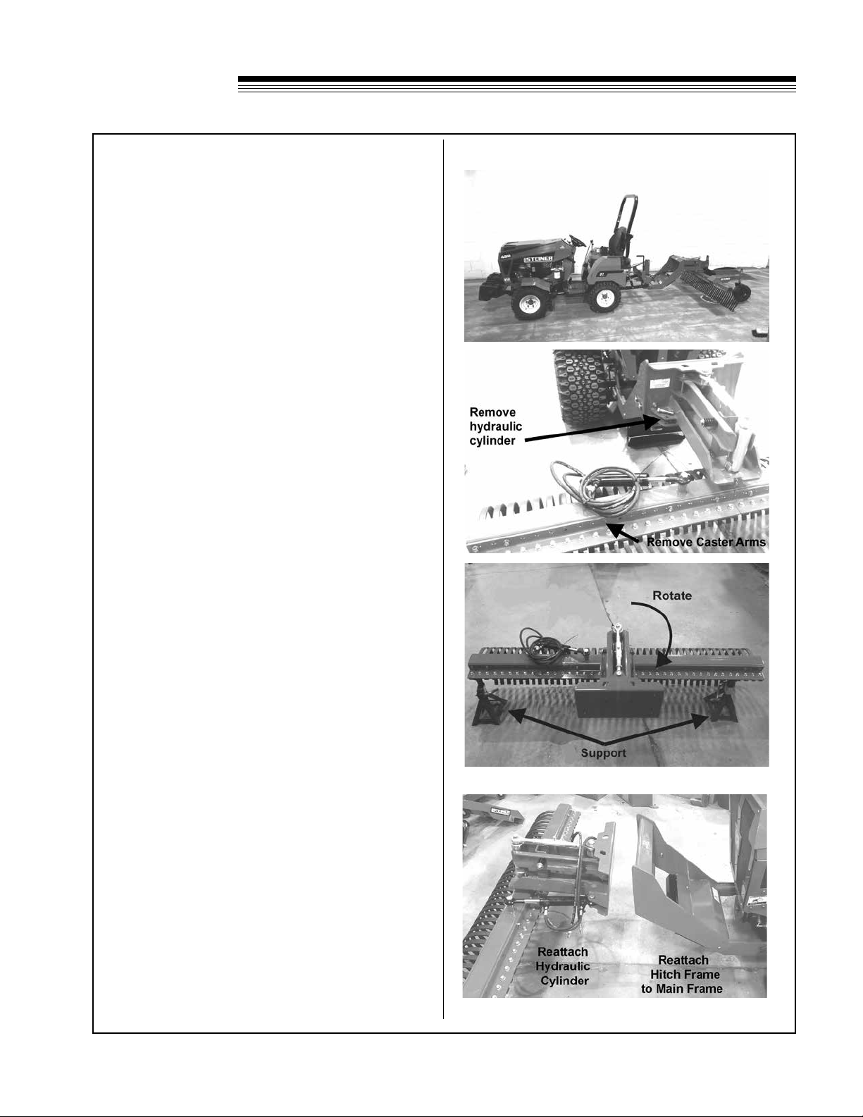
1. To setup the TR270 Terra Rake for use on the
3-Point Quick Hitch QH202, it is recommended to
rst attach the rake to the front of the tractor for
setup.
2. Remove hose clamps on the side of the quick hitch
frame and main frame of the rake.
3. Remove the caster arms.
4. Remove hydraulic cylinder from the main frame,and
secure the hydraulic hoses out of the way.
5. Support the rake so that it will not fall once
unbolted. Unbolt the main frame from the quick
hitch frame.
6. Rotate the main frame 180°.
7. Reattach hydraulic cylinder.
8. With the hitch frame still on tractor, reattach to the
main frame.
9. Place kickstand down and unhook the hitch frame
from the tractor.
12
TERRA
RAKE
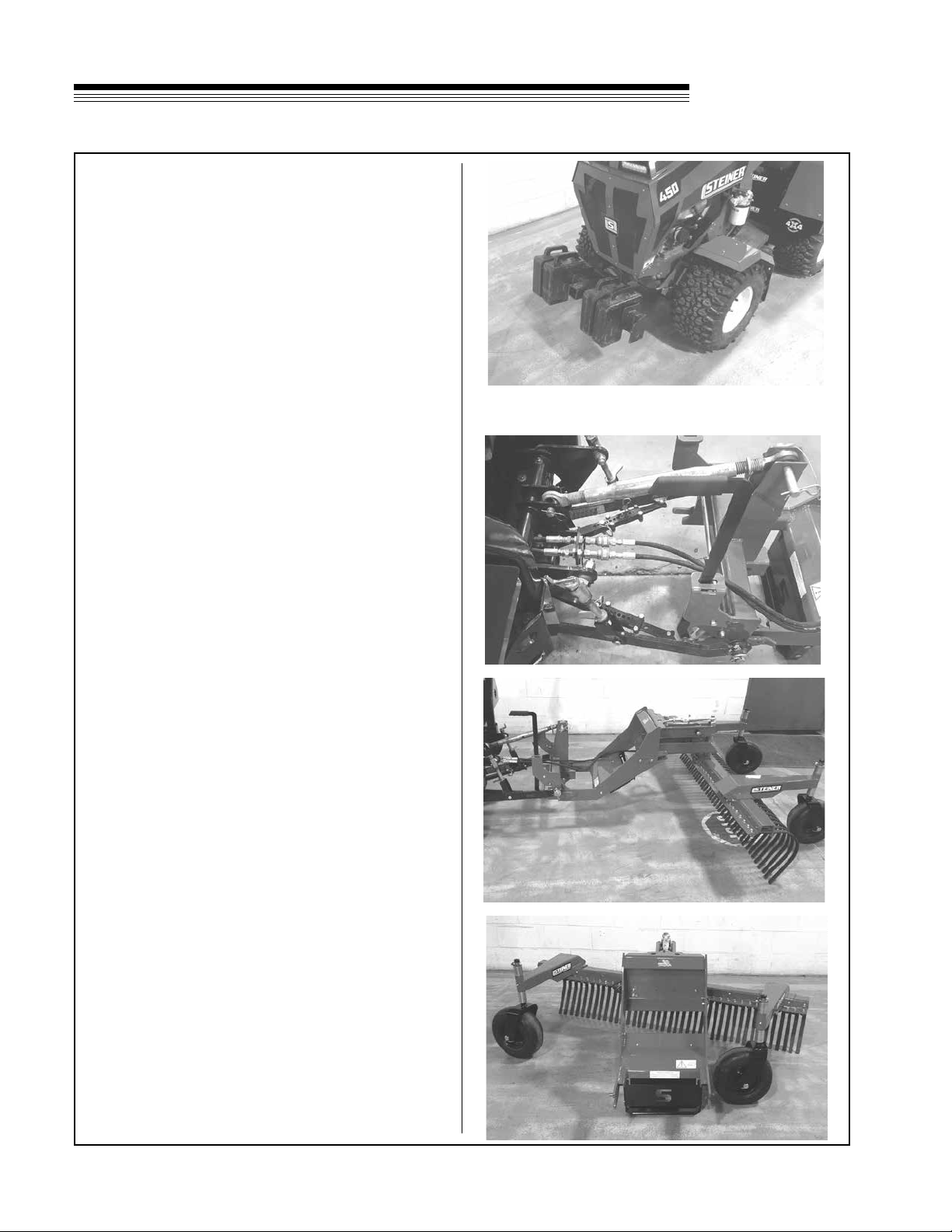
OPTIONAL 3-POINT HITCH MOUNTING
10. For stability, the 75-71203 WB200 Front Weight Bar
Kit and 75-71204 WB201 Weight Kit must be used
if the TR270 is mounted to the 3-point hitch.
11. Attach the terra rake to the 3-point quick hitch.
Reattach hose clamps to main frame and hitch
frame. Ensure hoses are not pinched or pulled too
tight.
12. Plug in hydraulic hoses to rear accessory ports.
13. Reinstall caster arms.
14. When mounted to the 3-point Quick Hitch adapter
and caster arms are mounted towards the tractor,
the caster arms must be mounted to the outside to
prevent contact.
13
TERRA
RAKE
MAINTENANCE / STORAGE
MAINTENANCE
DAILY INSPECTION AND MAINTENANCE
• Visual inspection for loose, missing or worn
components and replace if needed.
• Inspect for bent rake tines and replace as
needed.
• Check tire pressure.
• Inspect and grease pivot ball and caster
bushings as needed.
• Inspect hydraulic hoses and ttings for leaks,
deterioration, or damage.
• Inspect and lightly lube top link as needed.
ANNUAL INSPECTION AND MAINTENANCE
• Visual inspection for loose, missing or worn
components and replace if needed.
• Inspect for bent rake tines and replace as
needed.
• Check tire pressure.
• Inspect and grease pivot ball and caster
bushings as needed.
• Inspect and lubricate rod ends on top link.
• Inspect and lubricate rod ends on hydraulic
cylinder.
• Inspect caster wheel axles and bearings.
• Inspect hydraulic hoses and ttings for leaks,
deterioration, or damage.
TIRE PRESSURE
Tire pressure should be maintained at 40 psi.
WARNING
LUBRICATION LOCATIONS
3 points-Centerlink and wheel casters
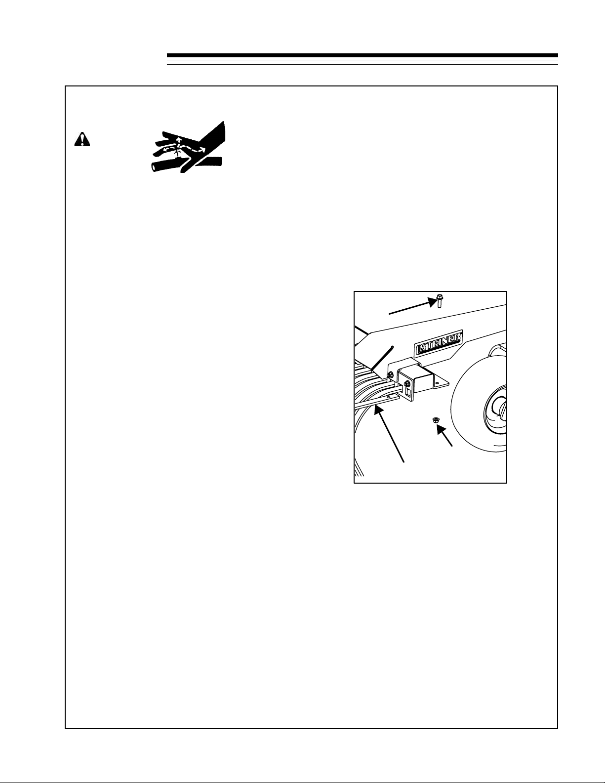
RAKE TINE REPLACEMENT
1. Park power unit on level surface and set the
parking brake.
2. Lower kickstand and lower rake to the ground.
Shut off the tractor.
3. Adjust top link so tines are off the ground.
4. Remove bolt Xand nut Y. Slide out old tine.
5. Insert new rake tine and attach to rake with bolt
Xand nut Y.
X
Y
Z
STORAGE
PLACING RAKE IN STORAGE
1. Clean the rake.
2. Inspect for loose or missing hardware, damaged
or worn parts. Repair or replace any damaged or
worn parts.
3. Apply grease to grease points. Wipe off excess
grease. Inspect and lightly lube top link as
needed.
REMOVING RAKE FROM STORAGE
1. Clean and inspect rake for use.


15
TERRA
RAKE
PARTS
SECTION
16
TERRA
RAKE
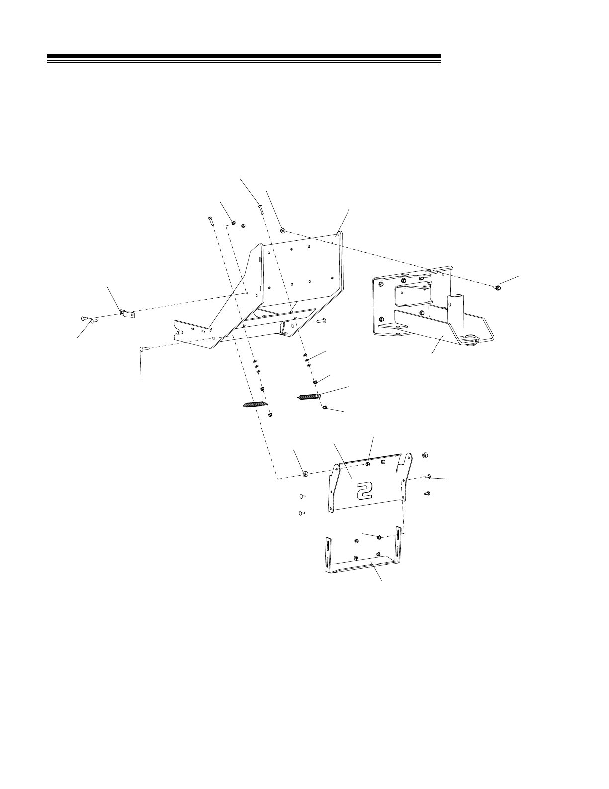
FIGURE 1
HITCH ASSEMBLY
15
11
7
81
6
3
5
2
4
9
19
10
12
14
13
11
11
11

17
ITEM PART NO. DESCRIPTION QTY ITEM PART NO. DESCRIPTION QTY
TERRA
RAKE FIGURE 1
HITCH ASSEMBLY
1 4177225.17 WLDMT-FRAME, MAIN 1
2 64268-03 NUT-FL NYLON LOCK 3/8-16 8
3 64262-011 BLT-FLG HD 3/8-16 X 1 8
4 64018-51 BLT-CRG 5/16-18 X 3/4 SN 4
5 64018-49 BLT-CRG 3/8-16 X 1-1/2 2
6 64018-34 BLT-CRG 5/16-18 X 1-1/2 2
7 4177754.7 BRKT-KICKSTAND LOWER 1
8 64163-02 WSHR .321X.593X11GA 6
9 64229-03 NUT-NYLON LOCK 3/8-16 2
10 4176763.17 CLAMP-HOSE 1
11 64268-02 NUT-FL NYLON LOCK 5/16-18 10
12 4177196.17 WLDMT-HITCH FRAME 1
13 64018-15 BLT-CRG 5/16-18X1 SN 2
14 4174797 SPRING, BBC 2
15 33030-07 IDLER BUSHING 2
16 4177753.7 BRKT-KICKSTAND UPPER 1
18
TERRA
RAKE
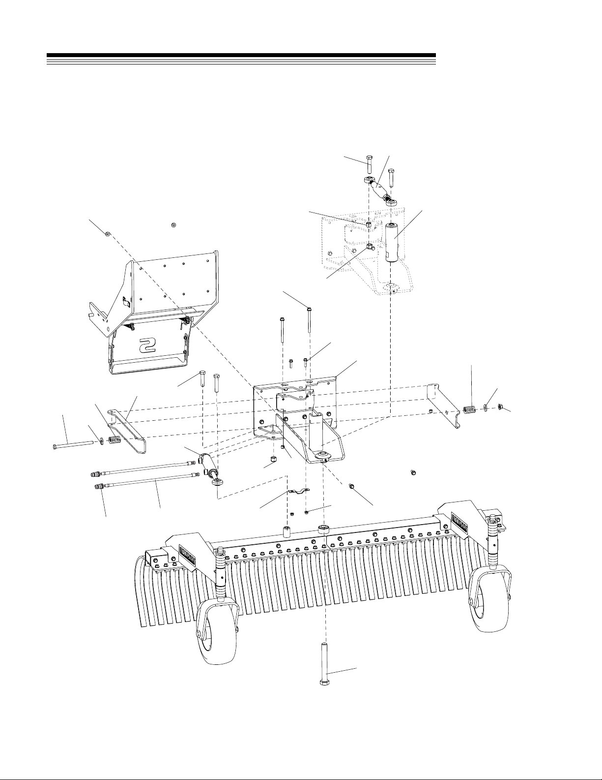
FIGURE 2
MAIN FRAME ASSEMBLY
10
16 9
14
21
12
13
7
1
8
64
3
5
2
18 20
15
19
17
11
13
10
16
22
23

19
ITEM PART NO. DESCRIPTION QTY ITEM PART NO. DESCRIPTION QTY
TERRA
RAKE FIGURE 2
MAIN FRAME ASSEMBLY
1 4177225.17 WLDMT-MAIN FRAME 1
2 4177210 TOP LINK 1
3 23-058 CYLINDER 1-1/2 X 5 DUMP 1
4 4176748 BAR-TINE FRAME CENTERING 1
5 64262-011 BLT-FLG HD 3/8-16 X 1 8
6 64268-03 NUT-FL NYLON LOCK 3/8-16 8
7 64123-342 BLT-HEX 1-14X7-1/2 1
8 64262-040 BLT-FLG HD 3/8-16 X 4-1/2 GR 8 2
9 4176753.17 ARM-CENTERING 2
10 64163-99 WSHR-.510X1.31X.179 2
11 64123-210 BLT-HEX 1/2-13X7-1/2 1
12 64123-325 BLT-HEX,5/8-11 X 3 3
13 64229-06 NUT-NYLON LOCK 5/8-11 2
14 64268-03 NUT-FL NYLON LOCK 3/8-16 2
15 64123-168 BLT-HEX 5/8-11X2-1/2 1
16 4177744 SPRING-COMPRESSION 1.25"X2" 2
17 4130974-01 SPACER-.625/.635x.88x.688 1
18 4176763 CLAMP-HOSE 1
19 64262-008 BLT-FLG HD 5/16-18 X 1-1/4 2
20 64268-02 NUT-FL NYLON LOCK 5/16-18 2
21 64268-05 NUT-FL NYLON LOCK 1/2-13 1
22 4177755-01 HOSE-M 1/4NPFT - M 1/4 NPFT X 75 2
23 23-004 MALE QUICK COUPLER 2
20
TERRA
RAKE
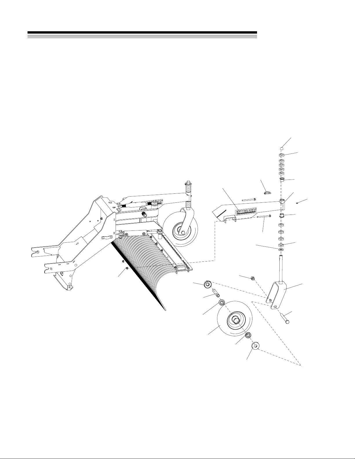
FIGURE 3
CASTER WHEEL ASSEMBLY
8
4
13
6
7
9
3
10
1
2
11
12
16
17
15
14
5
7
10
12
16
Table of contents
Other Steiner Farm Equipment manuals

Popular Farm Equipment manuals by other brands


Oregon
Oregon 480RC Original instruction manual

Wintex Agro
Wintex Agro WINTEX 1000 Workshop manual

Reese
Reese Aitchison Seedmatic 40 D Series manual

Yetter
Yetter 5000-025B owner's manual

FPM Agromehanika
FPM Agromehanika 627 152 ASSEMBLY / OPERATION/ MAINTENANCE, SPARE PARTS LIST

LELY
LELY HIBISCUS 1525 Master Operator's manual


