6
SAFETY RULES
Safety Rules
ATTENTION! Become alert! Your safety is involved!
Safety is a primary concern in the design and manufacture of our products. Unfortunately, our efforts to provide
safe equipment can be wiped out by an operator’s single careless act. In addition to the design and configuration
of equipment, hazard control and accident prevention are dependent upon the awareness, concern, judgment, and
proper training of personnel involved in the operation, transport, maintenance and storage of equipment. It has
been said “The best safety device is an informed, careful operator.” We ask you to be that kind of operator.
Training
• Safety instructions are important! Read all attachment and power unit manuals; follow all safety rules and
safety decal information. (Replacement manuals and safety decals are available from your dealer. To locate
your nearest dealer, check the Dealer Locator at OregonProducts.com, or in the United States and Canada call
1-800-525-8322.) Failure to follow instructions or safety rules can result in serious injury or death.
• If you do not understand any part of this manual and need assistance, see your dealer.
• Know your controls and how to stop engine and attachment quickly in an emergency.
• Operators must be instructed in and be capable of the safe operation of the equipment, its attachments, and all
controls. Do not allow anyone to operate this equipment without proper instructions.
• Never allow children or untrained persons to operate equipment.
Preparation
• Check that all hardware is properly installed. Always tighten to torque chart specifications unless instructed
otherwise in this manual.
• Always wear relatively tight and belted clothing to avoid getting caught in moving parts. Wear sturdy, rough-soled
work shoes and protective equipment for eyes, hair, hands, hearing, and head; and respirator or filter mask where
appropriate.
• Make sure attachment is properly secured, adjusted, and in good operating condition.
• Power unit must be equipped with ROPS or ROPS cab and seat belt. Keep seat belt securely fastened. Falling
off power unit can result in death from being run over or crushed. Keep foldable ROPS systems in “locked up”
position at all times.
• Remove accumulated debris from this equipment, power unit, and engine to avoid fire hazard.
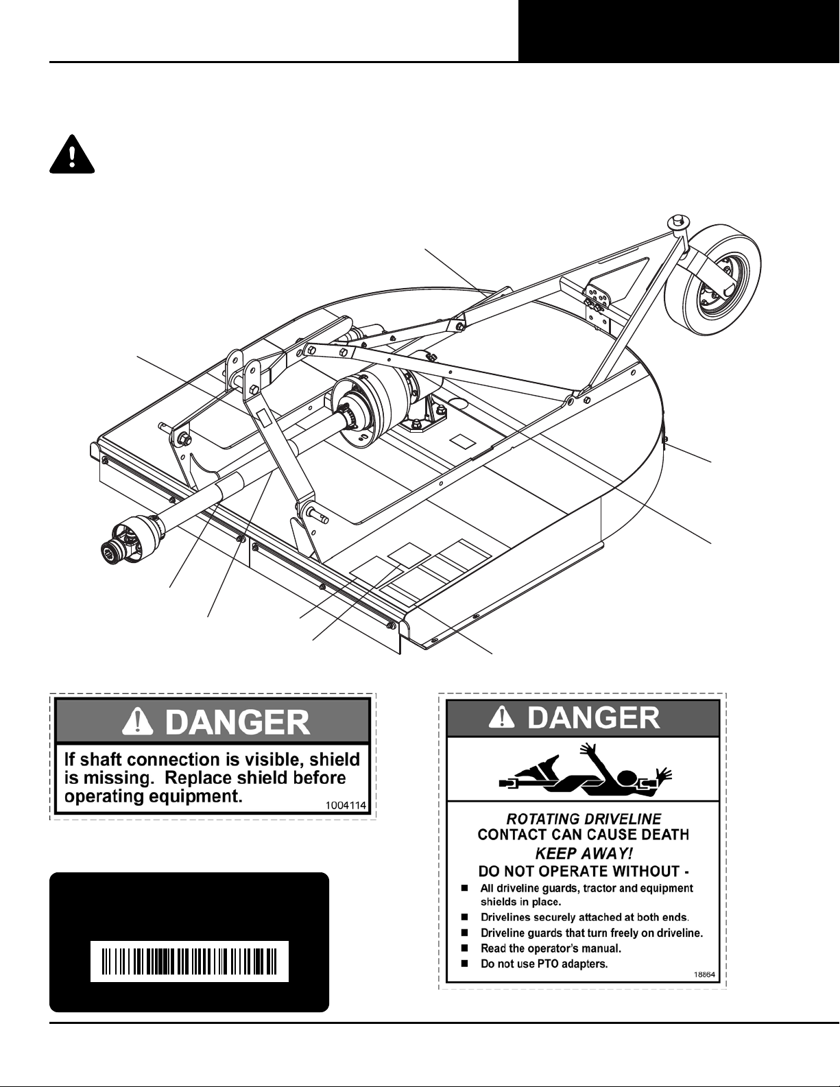
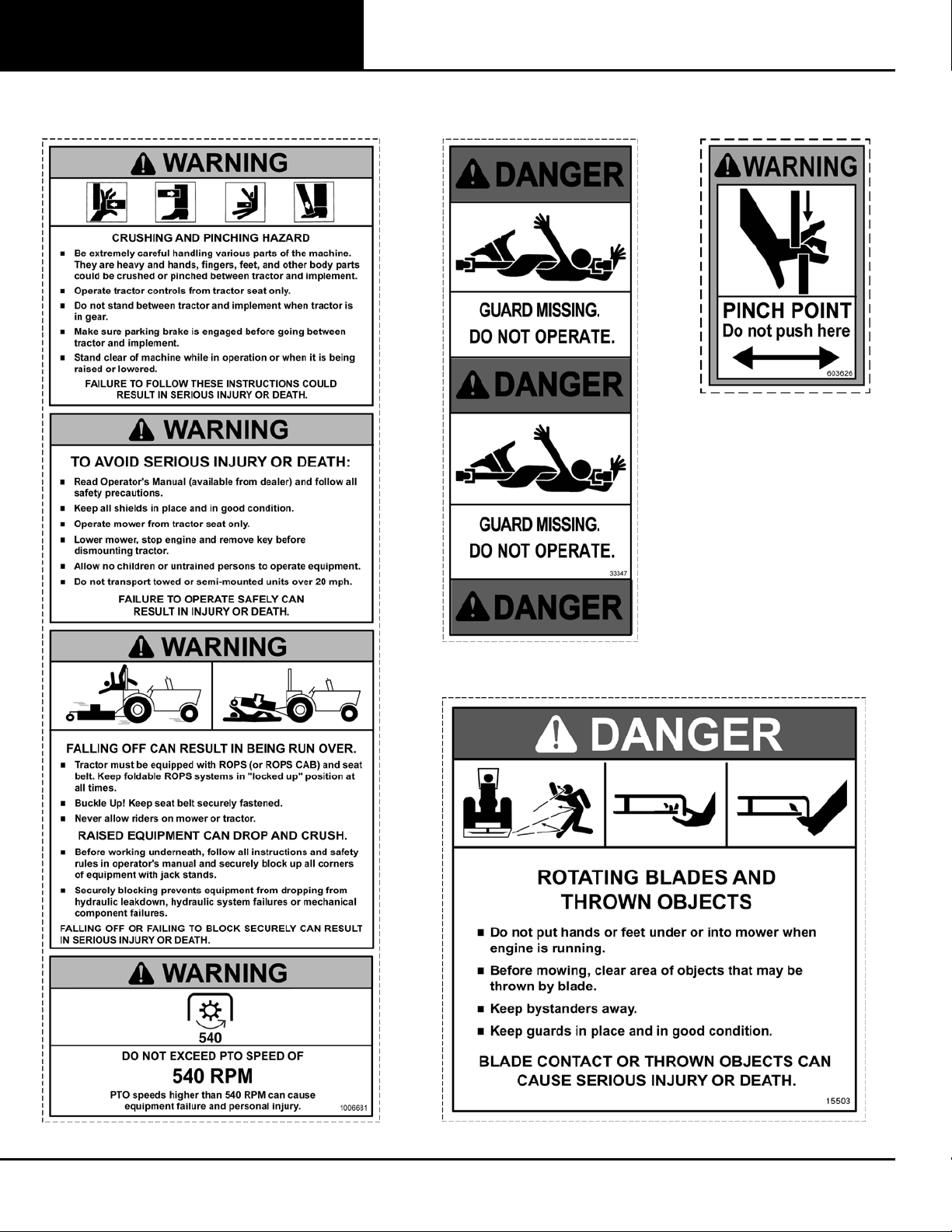
• Make sure all safety decals are installed. Replace if damaged. (See Safety Decals section for location.)
• Make sure shields and guards are properly installed and in good condition. Replace if damaged.
• A minimum 20% of tractor and equipment weight must be on the tractor front wheels when attachments are in
transport position. Without this weight, front tractor wheels could raise up resulting in loss of steering. The weight
may be attained with front wheel weights, ballast in tires, front tractor weights or front loader. Weigh the tractor and
equipment. Do not estimate.
• Inspect and clear area of stones, branches, or other hard objects that might be thrown, causing injury or damage.