Steiner SS244 Setup guide

OP/PARTS MANUAL
MAN 4174944
Rev. A 4-2017
MODELS:
75-70625A
SLIP SCOOP 44”SS244
75-70630A
SLIP SCOOP 48”SS248

CALIFORNIA PROPOSITION 65
WARNING: Cancer and Reproductive Harm - www.P65Warnings.ca.gov.
ADVERTENCIA: Cáncer y Dãno Reproductivo - www.65Warnings.ca.gov.

3
SLIP
SCOOP
IMPORTANT MESSAGE
Thank you for purchasing this Schiller Grounds Care. Inc. product. You have purchased a world class product,
one of the best designed and built anywhere.
This product comes with an Owner/Operator's Manual / Illustrated Parts List. The useful life and good service
you receive from this product depends to a large extent on how well you read and understand this manual. Treat
this product properly and adjust it as instructed, and it will give you many years of reliable service.
See a Schiller Grounds Care. Inc. dealer for any service or parts needed. Schiller Grounds Care. Inc. service
ensures that you continue to receive the best results possible from Schiller Grounds Care. Inc. products. You
can trust Schiller Grounds Care. Inc. replacement parts because they are manufactured with the same high
precision and quality as the original parts.
Schiller Grounds Care. Inc. designs and builds its equipment to serve many years in a safe and productive man-
ner. For longest life, use this product only as directed in the manual, keep it in good repair and follow safety
warnings and instructions. You'll always be glad you did.
Schiller Grounds Care. Inc.
One Bob Cat Lane
Johnson Creek, WI 53038-0469
4-2007
TABLE OF CONTENTS FIGURES PAGE
DESCRIPTION/SPECIFICATIONS .................................................................................................................. 4
SAFETY........................................................................................................................................................5, 6
ASSEMBLY INSTRUCTIONS .......................................................................................................................... 7
INSTALLATION/OPERATION...........................................................................................................................8
PARTS SECTION.............................................................................................................................................9
44" HYDRAULIC SLIP SCOOP PARTS .............. FIGURE 1 ................................................................... 10, 11
48" HYDRAULIC SLIP SCOOP PARTS .............. FIGURE 2 ................................................................... 12, 13
4
SLIP
SCOOP
DESCRIPTION/SPECIFICATIONS
SPECIFICATIONS
Model 75-70625 75-70630
Overall width:............................. 48" ............................................. 52"
Overall height: ........................... 16" ............................................. 16"
Overall length: ........................... 33" ............................................. 33"
Width of bucket:......................... 44" ............................................. 48"
Bucket Capacity:........................ 3.25 cubic ft. .............................. 3.5 cubic ft.
Dumping: ................................... Hydraulic.................................... Hydraulic
Weight ....................................... 135 lbs. ...................................... 170 lbs.
NOTE: Specications are subject to change without notice.
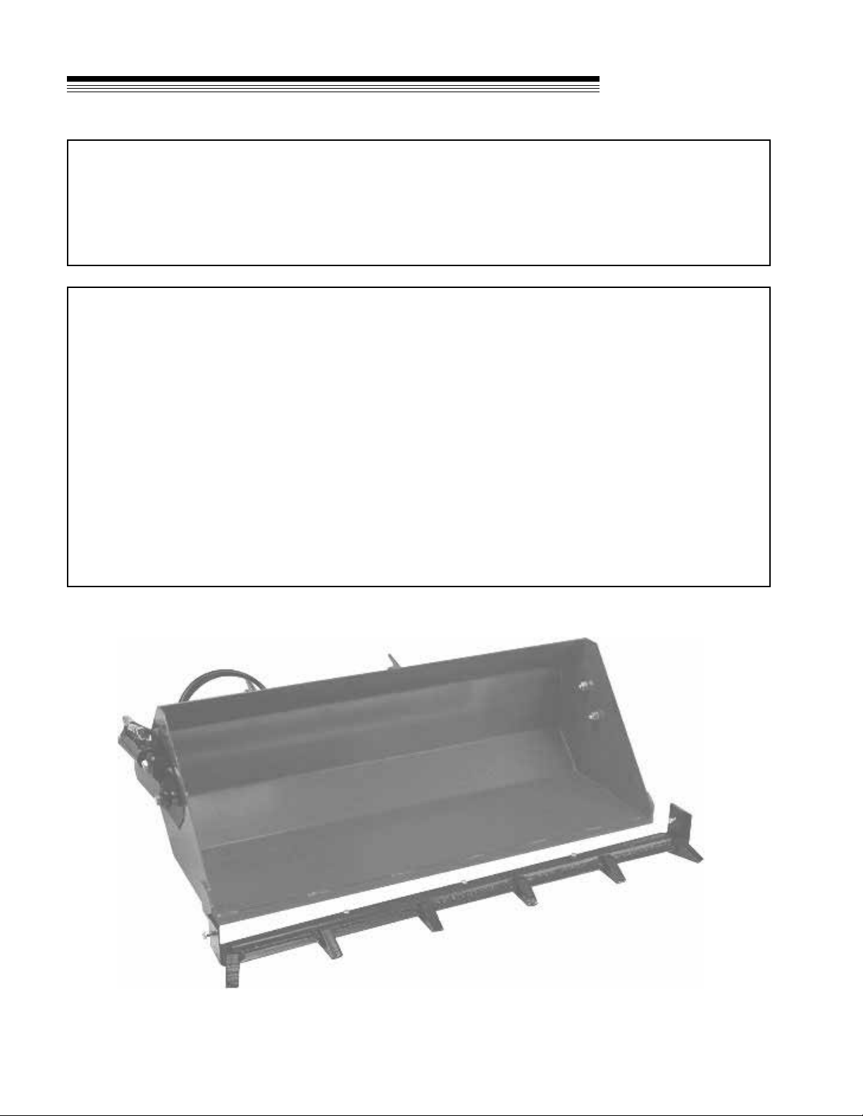
DESCRIPTION
The Slip Scoop attachment mounts on the quick hitch front lift of the power unit. On or off in a
minute or less, it is a quick, inexpensive way to relocate loose materials. Use it for landscaping, light
excavating and many tasks where you would normally use a wheelbarrow. Twin hydraulic cylinders control
the bucket position on hydraulic operated slip scoops.
5
SLIP
SCOOP
SAFETY
NOTICE !!!
Unauthorized modications may present extreme
safety hazards to operators and bystanders and
could also result in product damage.
Schiller Grounds Care. Inc. strongly warns against,
rejects and disclaims any modications, add-on
accessories or product alterations that are not
designed, developed, tested and approved by Schiller
Grounds Care. Inc. Engineering Department. Any
Schiller Grounds Care. Inc. product that is altered,
modied or changed in any manner not specically
authorized after original manufacture–including the
addition of “after-market” accessories or component
parts not specically approved by Schiller Grounds
Care. Inc.–will result in the Schiller Grounds Care.
Inc. Warranty being voided.
Any and all liability for personal injury and/or
property damage caused by any unauthorized
modications, add-on accessories or products not
approved by Schiller Grounds Care. Inc. will be
considered the responsibility of the individual(s) or
company designing and/or making such changes.
Schiller Grounds Care. Inc. will vigorously pursue
full indemnification and costs from any party
responsible for such unauthorized post-manufacture
modications and/or accessories should personal
injury and/or property damage result.
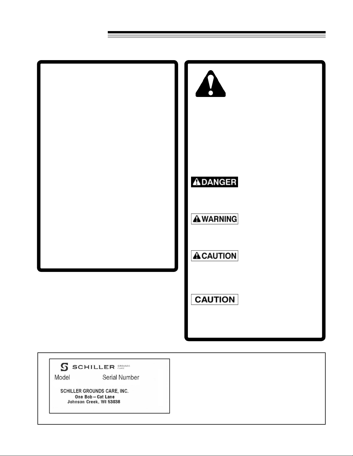
This symbol means:
ATTENTION!
BECOME ALERT!
Your safety and the safety of others is involved.
Signal word denitions:
The signal words below are used to identify levels
of hazard seriousness. These words appear in this
manual and on the safety labels attached to Schiller
Grounds Care. Inc. machines. For your safety and
the safety of others, read and follow the information
given with these signal words and/or the symbol
shown above.
DANGER indicates an imminently hazardous
situation which, if not avoided, WILL result in death
or serious injury.
WARNING indicates a potentially hazardous
situation which, if not avoided, COULD result in
death or serious injury.
CAUTION indicates a potentially hazardous situation
which, if not avoided, MAY result in minor or moderate
injury. It may also be used to alert against unsafe
practices or property damage.
CAUTION used without the safety alert symbol
indicates a potentially hazardous situation which, if
not avoided, MAY result in property damage
MODEL NUMBER: This number appears on
sales literature, technical manuals and price lists.
SERIAL NUMBER: This number appears only
on your unit. It contains the model number fol-
lowed consecutively by the serial number. Use
this number when ordering parts or seeking war-
ranty information.

6
SLIP
SCOOP
SAFETY
1. Read and understand the Owner’s Manual before attempting to operate this machine.
2. Operate all controls from the operator’s seat. NO RIDERS.
3. Keep all shields in place and safety switches adjusted properly.
4. Do not leave equipment unattended. STOP the engine and remove the key.
5. Do not allow minors or the inexperienced to operate this machine.
6. Keep people and pets a safe distance away from machine using power driven attachments. Injury could
result from ying debris.
GENERAL SAFETY
OPERATING SAFETY
1. Do not attempt to work on unit or any
attachments with engine running. STOP
ENGINE!
2. WARNING! The tractor may coast when the
engine stops.
3. Before leaving the tractor seat:
• Set Parking brake.
• Stop Engine.
CARRY LOADS LOW AND AVOID HIGH SPEEDS
OR QUICK, SHARP TURNS. A REAR WEIGHT
BAR SHOULD BE ADDED WITH WEIGHT EQUAL
TO THE SCOOP LOAD.

7
SLIP
SCOOP
ASSEMBLY INSTRUCTIONS
Refer to Pages 10 - 13 for Parts
Identication
Assembly Instructions 75-70625A
(Figure 1)
1. Unfasten the bucket (Fig. 1, Item 16) and the
sub-frame (Fig. 1, Item 15) from the sides of the
crate and remove.
2. Remove the hardware package from the crate
and open.
3. Loosen all ball joints prior to connecting them to
the bucket.
4. Place the bucket between the frame arms so that
the holes at the ends of the arms line up with the
lower set of holes on each side of the bucket.
5. Insert a 5/8 X 2-1/2 bolt (Fig. 1, Item 19) through
the rear end of each arm and place one 5/8 at
washer (Fig. 1, Item 12) and one spacer (Fig. 1
Item 5) on each bolt. Insert the bolts through the
lower holes on each side of the bucket. Place a
5/8 stover locknut (Fig. 1, Item 18) on each bolt
and tighten.
6. Insert a 5/8 X 2-3/4 bolt (Fig. 1, Item 3) through
the rod end of each cylinder (Fig. 1, Item 4) Place
a washer (Fig. 1, Item 12), and two spacers (Fig.
1, Item 5) on each bolt. Insert the bolts through
the upper holes on each side of the bucket.
Place a 5/8 stover locknut (Fig. 1, Item 18) on
each bolt and tighten.
7. If installing on a 430/440 or earlier tractor,
please locate the two loose couple hoses (Fig.
1, Item 7) and ttings (Fig. 1, Item 8) provided.
Remove ttings (Fig. 1, Item 21 & 22) and
existing hoses (Fig. 1, Item 20 & 23) from slip
scoop. Install hoses (Fig. 1, Item 7) and ttings
(Fig. 1, Item 8) the per illustration on page 10.
Insure hoses are clear from the wheels when
the scoop is raised and lowered. Adjust as
necessary.
Assembly Instructions 75-70630A
(Figure 2)
1. Unfasten the bucket (Fig. 2, Item 16) and the
sub-frame (Fig. 2, Item 15) from the sides of the
crate and remove.
2. Remove the hardware package from the crate
and open.
3. Loosen all ball joints prior to connecting them to
the bucket.
4. Place the bucket between the frame arms so that
the holes at the ends of the arms line up with the
lower set of holes on each side of the bucket.
5. Insert a 5/8 X 2-3/4 bolt (Fig. 2, Item 3) through
the lower hole on each side of the bucket.
(Through the outer bracket only.) Insert bolts
through the end of each arm and place one
washer (Fig. 2, Item 12) and two spacers (Fig. 2,
Item 5) on each bolt. Push the bolts through the
bucket. Place a 5/8 stover locknut (Fig. 2, Item
18) on each bolt and tighten.
6. Insert a 5/8 X 2-3/4 bolt (Fig. 2, Item 3) through
the upper hole on each side of the bucket.
(Through the outer bracket only.) Insert bolts
through the rod end of each cylinder
(Fig. 2, Item 4) and place one wahser (Fig. 2,
Item 12) and two spacers (Fig. 2, Item 5) on each
bolt. Push the bolts through the bucket. Place a
5/8 stover locknut (Fig. 2, Item 18) on each bolt
and tighten.
7. If installing on a 430/440 or earlier tractor,
please locate the two loose couple hoses (Fig.
2, Item 7) and ttings (Fig. 2, Item 8) provided.
Remove ttings (Fig. 2, Item 17 & 24) and hoses
( Fig. 2, Item 19 & 25) from slip scoop. Install
hoses (Fig. 1, Item 7) and ttings (Fig. 2, Item 8)
the per illustration on page 12. Insure hoses are
clear from the wheels when the scoop is raised
and lowered. Adjust as necessary.

8
SLIP
SCOOP
INSTALLATION/OPERATION
HYDRAULIC SLIP SCOOP OPERATION
1. Use “Low” (1) range for operating scoop.
2. Level the scoop, for loading materials, by moving the auxiliary hydraulic lever. To dig into the surface, the
front edge of the scoop must be lower than the rear.
3. When the scoop is loaded, move the auxiliary hydraulic lever to roll back the scoop to contain the load.
4. To dump the load, move the auxiliary hydraulic lever.
NOTE: A rear weight bar is recommended to use with the Slip Scoop. Add weights equal to the load carried
in the scoop. Remove weights when the Slip Scoop is removed.
HINTS FOR OPERATION OF HYDRAULIC SLIP SCOOP
A. Use “FLOAT” position for loading loose materials on a rm surface.
B. Use DOWN PRESSURE to dig into rm surfaces.
C. To level loose materials, roll the bucket to the extreme dump position. Lower the scoop and move
backward to get a back blade leveling effect. Use a little down pressure.
HYDRAULIC SLIP SCOOP INSTALLATION
1. Attach the slip scoop to the front lift.
2. Attach the hydraulic hoses to the auxillary couplers. Route the hoses in a place where they will not be
damaged. If the hydraulic lever movement seems backward, reverse the hoses at the quick couplers..

9
SLIP
SCOOP
PARTS SECTION
PARTS
SECTION

10
SLIP
SCOOP
44" HYDRAULIC SLIP SCOOP PARTS
FIGURE 1
430/440
SET UP
450
SET UP
20
23
21
22
21
25
24

11
SLIP
SCOOP
ITEM PART NO. DESCRIPTION QTY ITEM PART NO. DESCRIPTION QTY
44" HYDRAULIC SLIP SCOOP PARTS
FIGURE 1
1 25-2103-4-6 90-M/M 9/16 JIC x 1/8 NPTF 4
2 20-217 HOSE-1/4 X 20 2
3 90-1022 BOLT-5/8 X 2-3/4 4
4 23-058 CYLINDER-1-1/2 X 5 2
21-0A009066 SEAL KIT-CYLINDER 1
5 64163-12 .635/.640X1.0X.25 WASH 10
6 25-033T-6-6 FITTING-TEE 2
7 20-074 HOSE-1/4 X 31 2
(430/440 MODEL ONLY)
8 25-0103-4-6 FITTING 2
(430/440 MODEL ONLY)
9 23-004 QUICK COUPLER-MALE 2
10 20-029 HOSE-1/4 2
11 64229-01 NUT-NYON LOCK 1/4-20 3
12 64163-93 WASHER 6
13 4165751 CLAMP-HOSE 1/2 3
14 64123-07 BLT-HEX 1/4-20 X 1-1/2 3
15 4177009 S-FRAME 1
16 62-735.17 BUCKET 1
17 64-999.7 KICKSTAND 1
18 99-A10 NUT-STOVER LOCK 5/8-11 6
19 90-1020 BOLT-5/8 X 2-1/2 2
20 20-027 HOSE (1/4 X 22) 1
(450 MODEL ONLY)
21 25-3903-6-6 FTG 90 -6 MJIC X -6 F.JIC 2
(450 MODEL ONLY)
22 25-2103-4-6 90-M/M 9/16 JIC x 1/8 NPTF 2
(450 MODEL ONLY)
23 20-006 HOSE 1/4 X 24 100R1 #6 JIC 1
(450 MODEL ONLY)
* 4116761 DECAL-MADE IN THE USA 1
* 4158620 DECAL-STEINER 1
24 43067A COLLAR, SET, PLATE 1
25 02-PP0313 PRESTO PIN-3/32 X 1-5/8 1
*NOT ILLUSTRATED

12
SLIP
SCOOP
430/440
SET UP
450
SET UP
19
25
24
17
24
48" HYDRAULIC SLIP SCOOP PARTS
FIGURE 2

13
SLIP
SCOOP
ITEM PART NO. DESCRIPTION QTY ITEM PART NO. DESCRIPTION QTY
1 25-2103-4-6 90-M/M 9/16 JIC x 1/8 NPTF 4
2 20-027 HOSE (1/4 X 22) 2
3 90-1022 BOLT-5/8 X 2-3/4 6
4 23-058 CYLINDER-1-1/2 X 5 2
21-0A009066 SEAL KIT-CYLINDER 1
5 64163-12 .635/.640X1.0X.25 WASH 12
6 25-033T-6-6 FITTING-TEE 2
7 20-074 HOSE-1/4 X 31 2
(430 / 440 MODELS ONLY)
8 25-0103-4-6 FITTING 2
(430 / 440 MODELS ONLY)
9 23-004 QUICK COUPLER-MALE 2
10 20-022 HOSE-1/4 2
11 64229-01 NUT-NYON LOCK 1/4-20 4
12 64163-93 WASHER 6
13 4165751 CLAMP-HOSE 1/2 4
14 64123-07 BLT-HEX 1/4-20 X 1-1/2 4
15 4177008 S-FRAME 1
16 64-984.17 BUCKET 1
17 25-2103-4-6 90-M/M 9/16 JIC x 1/8 NPTF 2
(450 MODEL ONLY)
18 99-A10 LOCKNUT-5/8 STOVER 6
19 20-027 HOSE (1/4 X 22) 1
(450 MODEL ONLY)
20 43067A COLLAR, SET, PLATE 1
21 02-PP0313 PRESTO PIN-3/32 X 1-5/8 1
22 64-999.7 KICKSTAND 1
23 85010N GREASE FITTING 2
24 25-3903-6-6 FTG 90 -6 MJIC X -6 F.JIC 2
(450 MODEL ONLY)
25 20-006 HOSE 1/4 X 24 100R1 #6 JIC 1
(450 MODEL ONLY)
* 4116761 DECAL-MADE IN THE USA 1
* 4158620 DECAL-STEINER 1
*NOT ILLUSTRATED
48" HYDRAULIC SLIP SCOOP PARTS
FIGURE 2

SCHILLER GROUNDS CARE, INC.
ONE BOB-CAT LANE
P.O. BOX 469
JOHNSON CREEK, WI 53038
920-699-2000
www.schillergc.com ©Schiller Grounds Care, Inc. 2010
Other manuals for SS244
1
This manual suits for next models
3
Table of contents
Other Steiner Farm Equipment manuals


