STELL CITY 30-300 User manual

VER.06.2016R1
Should you require assistance,
please have available your:
Model no.: __________________
Serial no.: __________________
JOINTER 8”
OWNER’S MANUA
30-300

Page 2
TAB E OF CONTENTS
INTRODUCTION
This user manual is intended for use by anyone working with this machine. It should be kept available
for immediate reference so that all operations can be performed with maximum efficiency and safety.
Do not attempt to perform maintenance or operate this machine until you have read and understand
the information contained in this manual.
The drawings, illustrations, photographs, and specifications in this user manual represent your machine
at time of print. However, changes may be made to your machine or this manual at any time with no
obligation to Steel City.
INTRODUCTION ....................................................................................2
TAB E OF CONTENTS..........................................................................2
WARRANTY ...........................................................................................3
FEATURES.............................................................................................4
PRODUCT SPECIFICATIONS ...............................................................4
GENERA SAFETY................................................................................5
PRODUCT SAFETY...............................................................................7
E ECTRICA AND GROUNDING INSTRUCTIONS..............................8
UNPACKING AND INVENTORY ............................................................9
ASSEMB Y...........................................................................................10
ADJUSTMENTS ...................................................................................13
MAINTENANCE ...................................................................................15
ADJUSTMENTS ...................................................................................19
PARTS IST .........................................................................................21

Page 3
WARRANTY
STEEL CITY WARRANTY
The manufacturer warrants its machines to be free from defects in workmanship and materials for a period of
2 years from the date of the original purchase for Steel City shop machines or for a period of 1 year for Titanium
production machines; subject to the following conditions :
A- Warranty applies to the original buyer only and may not be transferred. Original proof of purchase is
required.
B- Warranty is void if repairs or alterations are made to the machine by an unauthorized service center without
the direct consent of the manufacturer or its representative.
C- Warranty does not include defects, failures or breakages directly or indirectly caused by or resulting from
improper use, improper or lack of maintenance, abuse or misuse, negligence, accidents, damages in
handling or transportation, or normal wear and tear of any part or component.
D- Accessories and wear items such as motor, switch, bearings, drive belt or other accessories are covered
for 1 year.
E- Consumables such as blades, knives, bits, sandpaper or others are not covered.
To file a warranty claim, customer may contact his dealer or email [email protected]
The manufacturer or its representative will inspect, repair or replace any part that has proven to be defective in
workmanship or material, provided that the customer sends the product prepaid to a designated authorized
service center and provides reasonable time to proceed.
If judged on warranty, the manufacturer or its representative will return the repaired product prepaid or will replace
it by a new one at its choice. On the contrary, if it is determined that there is no defect or that the problem resulted
from causes not within the scope of the warranty, it will dispose of or return the product at customer’s expenses,
following customer’s instructions.
The manufacturer or its representative shall not be held liable for any special, indirect, incidental, punitive or
consequential damages, including and without limitation loss of profits arising from or related to the warranty,
the breach of any agreement, the operation or the use of its machines.
Note:
The specifications in this manual are provided for informational purposes only and are subject to rectification
without notice. Some measures have been slightly rounded for ease of reading. Unless otherwise noted, they
should be considered for reference only.
Steel City reserves the right to make certain improvements to the design and appearance of its machines,
components, accessories or parts without notice and without the obligation to perform them on existing models.

Page 4
Motor 2 HP
Voltage 220 V only
Amps 8
Hertz 60
Table size 9 ¼’’ x 75 3/16” (234 x 1910 mm)
Table height 32 5/8’’ (830 mm)
Max. cutting width 8’’ (203 mm)
Max. cutting depth ½’’ (13 mm)
Rabbeting capacity ½’’ (13 mm)
Fence size 4’’ x 38’’ (102 x 965 mm)
Cutterhead speed 5500 rpm
Number of knives 3 / 22 (helical)
Base dimensions 28-1/2’’ x 17-5/16’’ (724 x 440 mm)
PRODUCT SPECIFICATIONS
Page 5
TO AVOID serious injury and damage to the machine,
read and follow all Safety and Operating Instructions be-
fore assembling and operating this machine.
All federal and state laws and any regulations having ju-
risdiction covering the safety requirements for use of this
machine take precedence over the statements in this
manual. Users of this machine must adhere to all such
regulations.
Below is a list of symbols that are used to attract your at-
tention to possible dangerous conditions.
This is the safety alert symbol. It is used to alert you to
potential personal injury hazards. Obey all safety mes-
sages that follow this symbol to avoid possible injury or
death.
Indicates an imminently hazardous situation which, if not
avoided, WI result in death or serious injury.
Indicates a potentially hazardous situation which, if not
avoided, COU D result in death or serious injury.
This symbol is used to alert the user to useful information
about proper operation of the machine.
Exposure to the dust created by power sanding, sawing,
grinding, drilling and other construction activities may
cause serious and permanent respiratory or other injury,
including silicosis (a serious lung disease), cancer, and
death. Avoid breathing the dust, and avoid prolonged
contact with dust. The dust may contain chemicals
known to the State of California to cause cancer, birth
defects or other reproductive harm.
Some examples of these chemicals are:
• ead from lead-based paints.
• Crystalline silica from bricks, cement and other
masonry products.
• Arsenic and chromium from chemically-treated
lumber.
Always operate tool in well ventilated area and provide
for proper dust removal. Use a dust collection system
along with an air filtration system whenever possible. Al-
ways use properly fitting NIOSH/OSHA approved respi-
ratory protection appropriate for the dust exposure, and
wash exposed areas with soap and water.
WARNING
!
!
DANGER
!
NOTICE
WARNING
!
WARNING
!
GENERA SAFETY
This manual is not totally comprehensive. It does
not and can not convey every possible safety and
operational problem which may arise while using
this machine. The manual will cover many of the
basic and specific safety procedures needed in an
industrial environment.
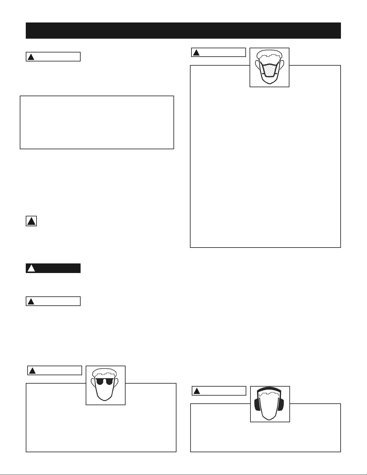
A WAYS wear eye protection. Any machine can throw
debris into the eyes during operations, which could cause
severe and permanent eye damage. Everyday eye-
glasses are NOT safety glasses.
A WAYS wear Safety Goggles (that comply with ANSI
standard Z87.1) when operating power tools.
WARNING
!
A WAYS wear hearing protection. Plain cotton is not an
acceptable protective device. Hearing equipment should
comply with ANSI S3.19 Standards.
1. To avoid serious injury and damage to the machine,
read the entire User Manual before assembly and op-
eration of this machine.
2. Serious personal injury may occur if normal safety
precautions are overlooked or ignored. Accidents are
frequently caused by lack of familiarity or failure to pay
attention. Obtain advice from supervisor, instructor, or
another qualified individual who is familiar with this
machine and its operations.
3, STOP using this machine, if at any time you experience
difficulties in performing any operation. Contact your
supervisor, instructor or machine service center
immediately.
WARNING
!

Page 6
4. Prevent electrical shock. Follow all electrical and
safety codes, including the National Electrical Code
(NEC) and the Occupational Safety and Health Reg-
ulations (OSHA). All electrical connections and wiring
should be made by qualified personnel only.
5. A WAYS be sure that the power switch is in the
“OFF” position and unplug the machine from the elec-
trical receptacle when making adjustments, changing
parts or performing any maintenance.
6. AVOID ACCIDENTA STARTING. Make sure that
the power switch is in the “OFF” position before plug-
ging in the power cord to the electrical receptacle.
7. NEVER leave a machine running, unattended. Turn
the power switch to the OFF position. DO NOT leave
the machine until it has come to a complete stop.
8. THE USE of extension cords is not recommended for
230V equipment. It is better to arrange the place-
ment of your equipment and the installed wiring to
eliminate the need for an extension cord. If an exten-
sion cord is necessary, refer to the chart in the
Grounding Instructions section to determine the min-
imum gauge for the extension cord. The extension
cord must also contain a ground wire and plug pin.
9. DO NOT pull a machine by the power cord. NEVER
allow the power cord to come in contact with sharp
edges, hot surfaces, oil or grease.
10. DO NOT unplug a machine by pulling on the power
cord. A WAYS grasp the plug, not the cord.
11. REP ACE a damaged cord immediately. DO NOT
use a damaged cord or plug. If the machine is not op-
erating properly, or has been damaged, left outdoors
or has been in contact with water.
12. NEVER remove any chips without turning off the
machine and disconnecting the power.
13. NEVER turn on the machine if the workpiece is in
contact with the cutterhead.
14. ENSURE that the machine sits firmly on the floor be-
fore using. If the machine wobbles or is unstable, cor-
rect the problem by using shims or blocks prior to
operation.
WARNING
!
TO REDUCE the risk of electrical shock. DO NOT use
this machine outdoors. DO NOT expose to rain or mois-
ture. Store indoors in a dry area. DO NOT handle the
plug with wet hands.
15. A WAYS keep hands and fingers away from the
blades when operating.
16. DO NOT FORCE the machine to perform an opera-
tion for which it was not designed. It will do a safer
and higher quality job by only performing operations
for which the machine was intended.
17. Every work area is different. Always consider safety
first, as it applies to your work area. Use this machine
with respect and caution. Failure to do so could result
in serious personal injury and damage to the ma-
chine.
18. DO NOT stand on a machine. Serious injury could re-
sult if it tips over or you accidentally contact any mov-
ing part.
19. DO NOT store anything above or near the machine.
20. REMOVE A MAINTENANCE TOO S from the im-
mediate area prior to turning the machine ON.
21. MAINTAIN your balance. DO NOT extend yourself
over the tool. Wear oil resistant rubber soled shoes.
Keep floor clear of debris, grease, and wax.
22. DO NOT operate any machine or tool if under the in-
fluence of drugs, alcohol, or medication.
23. MAINTAIN all machines with care. A WAYS KEEP
machine clean and in good working order. KEEP all
blades and tool bits sharp.
24. EACH AND EVERY time, check for damaged parts
prior to using any machine. Carefully check all guards
to see that they operate properly, are not damaged,
and perform their intended functions. Check for align-
ment, binding or breakage of all moving parts. Any
guard or other part that is damaged should be imme-
diately repaired or replaced. KEEP cutterhead knives
sharp and free of all rusT and pitch.
25. Safety decals are on this machine to warn and direct
you to how to protect yourself or visitors from per-
sonal injury. These decals MUST be maintained so
that they are legible. REP ACE decals that are not
legible.

Page 7
1.USE push blocks to move piece from the infeed table
to the outfeed table.
2. DO NOT use a jointer on pieces less than 10” in
length.
PRODUCT SAFETY
3. NEVER use a jointer with the depth of cut at more than
1⁄8”.
4. MAINTAIN the proper relationship between the infeed
and outfeed tables and the cutterhead knives.
26.KEEPprotective guards in place and in working
order.
27.Check material for loose knots, nails and other de-
fects.
28.AWAYSkeep the work area clean, well lit, and or-
ganized. DO NOTwork in an area that has slippery
floor surfaces from debris, grease, and wax.
29.SECUREall work. When it is possible, use clamps or
jigs to secure the workpiece. This is safer than at-
tempting to hold the workpiece with your hands.
30.STAY AERT, watch what you are doing, and use
common sense when operating any machine. DO
NOToperate any machine tool while tired or under
the influence of drugs, alcohol, or medication. A mo-
ment of inattention while operating power tools may
result in serious personal injury.
31.USE ONYrecommended accessories. Use of incor-
rect or improper accessories could cause serious in-
jury to the operator and cause damage to the
machine. If in doubt, DO NOTuse it.
32. Wear proper clothing, DO NOT wear loose clothing,
gloves, neckties, or jewelry. These items can get
caught in the machine during operations and pull the
operator into the moving parts. Users must wear a
protective cover on their hair, if the hair is long, to pre-
vent it from contacting any moving parts.
33. Keep visitors and children away from any machine.
DO NOT permit people to be in the immediate work
area, especially when the machine is operating.
34. DO NOT use a machine as a toy.
35. DO NOT use electrical tools in the presence of flam-
mable liquids or gasses.
36. A WAYS feed against the rotation of the cutterhead.
Never apply feed pressure with your hands directly
over the cutterhead. Always lift your hands, one at a
time, over the cutterhead as you pass the work along
the jointer bed. Always support the workpiece and
maintain control throughout the operation.
37. SAVE these instructions and refer to them frequently
and use them to instruct other users.
38. Establish a SAFETY ZONE around shop machinery.
A clearly defined “no-go” zone on the floor around
each machine. Take a few moments to either paint
(using non-slip paint) or using tape, define on the floor
the limits or perimeter of each machines safety zone.
WARNING
!
CHI DPROOF THE WORKSHOP AREA by removing
switch keys, unplugging tools from the electrical recep-
tacles, and using padlocks. DO NOT use near or around
children.
Page 8
E ECTRICA AND GROUNDING INSTRUCTIONS
WARNING
!
To reduce the risk of electric shock, follow all electrical
and safety codes, including the National Electric Code
(NEC) and the Occupational Safety and Health Regula-
tions (OSHA). All electrical connections and wiring should
be made by qualified personnel only.
WARNING
!
This machine MUST BE GROUNDED while in use to
protect the operator from electric shock.
In the event of a malfunction or breakdown, GROUND-
ING provides the path of least resistance for electric cur-
rent and reduces the risk of electric shock. The plug
MUST be plugged into a matching electrical receptacle
that is properly installed and grounded in accordance
with A local codes and ordinances.
If a plug is provided with your machine DO NOT modify
the plug. If it will not fit your electrical receptacle, have a
qualified electrician install the proper connections to meet
all electrical codes local and state. All connections must
also adhere to all of OSHA mandates.
IMPROPER E ECTRICA CONNECTION of the equip-
ment-grounding conductor can result in risk of electric
shock. The conductor with the green insulation (with or
without yellow stripes) is the equipment-grounding con-
ductor.
DO NOT connect the equipment-grounding conductor to
a live terminal if repair or replacement of the electric cord
or plug is necessary.
Check with a qualified electrician or service personnel if
you do not completely understand the grounding instruc-
tions, or if you are not sure the tool is properly grounded.
MINIMUM RECOMMENDED GAUGE FOR EXTENSION CORDS (AWG)
115/230 VO T OPERATION ON Y
25’ long 50’ long 100’ long
0 to 6 Amps 18 AWG 16 AWG 16 AWG
6 to 10 Amps 18 AWG 16 AWG 14 AWG
10 to 12 Amps 16 AWG 16 AWG 14 AWG
12 to 15 Amps 14 AWG 12 AWG Not
recommended
WARNING
!
MAKE SURE the circuit breaker does not exceed the rat-
ing of the plug and receptacle.
WARNING
!
To reduce the risk of fire or electrical shock, use the
proper gauge of extension cord. When using an ex-
tension cord, be sure to use one heavy enough to
carry the current your machine will draw.
EXTENSION CORDS
P UGS/RECEPTAC ES
The smaller the gauge-number, the larger the diameter
of the extension cord is. If in doubt of the proper size of
an extension cord, use a shorter and thicker cord. An un-
dersized cord will cause a drop in line voltage resulting
in a loss of power and overheating.
USE ON Y a 3-wire extension cord that has a 3-prong
grounding plug and a 3-pole receptacle that accepts the
machine’s plug.The third prong is used to ground the tool
and provide protection against accidental electric shock.
DO NOT remove the third.
If you are using an extension cord outdoors, be sure it is
marked with the suffix “W-A” (“W” in Canada) to indicate
that it is acceptable for outdoor use.
Make certain the extension cord is properly sized, and in
good electrical condition. Always replace a worn or dam-
aged extension cord immediately or have it repaired by
a qualified person before using it.
Protect your extension cords from children, sharp ob-
jects, excessive heat, and damp or wet areas.
WARNING
!
MAGNETIC SAFETY SWITCH
If the machine is equipped with a magnetic safety switch
you must to reset the overload protection switch after an
overload.
1. Remove the control box cover.
2. Press the reset button.
3. Reinstall the control box cover.
Make certain that the machine is disconnected
from the power source
WARNING
!
Page 9
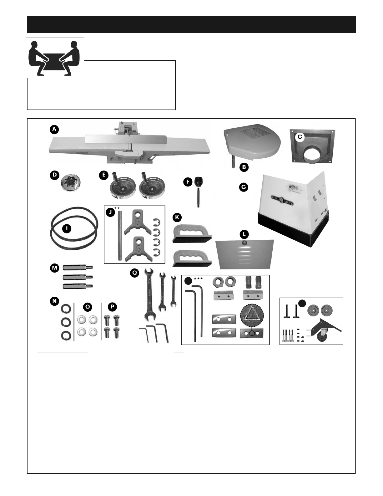
The jointer is very heavy. At least four peoples
will be required to unpack and lift.
Carefully remove the jointer, components and tools from
shipping carton. Check for damaged or missing items as per
list below.
Please report any damaged or missing part to your
Steel City dealer immediately.
IST OF CONTENTS QTY
A- JOINTER ASSEMB Y W/FENCE.................................... 1
B- CUTTER HEAD GUARD................................................. 1
C- DUST PORT..................................................................... 1
D- 4” HAND WHEE ............................................................ 1
E- 6” HAND WHEE ............................................................ 2
F- FENCE TI T EVER ....................................................... 1
G - BASE................................................................................1
I- V BE T............................................................................. 2
J** - KNIFE SETTING GAUGE
Knife setting gauge rod .................................................. 1
Knife setting gauge foot ................................................. 2
E-clip ............................................................................... 4
K- PUSH B OCK ................................................................. 2
- BASE DOOR....................................................................1
M- MOUNTING BO T .......................................................... 3
N- OCK WASHER.............................................................. 3
O- F AT WASHER................................................................. 4
P- PHI IPS HEAD SCREW................................................. 4
Q- TOO S
8-10 mm open end wrench................................................1
11-13 mm open end wrench..............................................1
12-14 mm open end wrench..............................................1
3 mm Allen key ..................................................................1
4 mm Allen key ................................................................ .1
5 mm Allen key ................................................................ .1
R*** -
HE ICA CUTTER HEAD TOO S / REP ACEMENT PARTS
5 mm Allen key .............................................................. .. 2
Nut ................................................................................... 4
Screw ................................................... ........................... 4
Knife-holder / chipbreaker ................................................ 4
Carbide insert (standard) .................................................2
Carbide insert (for rabbeting) ........................................... 1
S- CASTER ASSEMB Y:
OCKING NUT M8*1.25P (13B*9H) .................................2
HEX. BO T M8*1.25P*60 .................................................4
FOOT PAD ........................................................................2
HEX NUT M8*1.25P (13B*6.5H) .......................................4
CASTER ...........................................................................2
IVE CASTER....................................................................1
S
** Not supplied with model 30-300 HS3 / *** Supplied with model 30-300 HS3 only
R
UNPACKING AND INVENTORY

Page 10
ASSEMB Y
CASTERS
1. Place the stand up side down on the
floor and use the cardboard to pro-
tect from scratching.
2.Place a caster in the cen-
ter of a braket and align
both braket caster hole.
3.Put M8 hex screw and fix
the hex nut by using #13
wrench.
4. Repeat the procedures
for the other caster.
5. Place the movable caster in the center of
the stand square tube and align holes.
6.Put M8 hex screws and fix the hex nuts by
usign #13 wrench.
7.Insert hex nuts to foot pad screws.
8. Fix the assembled foot pads to the stand. Don’t tight
them.
9.Turn the stand side up and test if the stand is stable. Ad-
just foot pads if necessary and tight the hex nuts.
Page 11
Note: should you decide to install the caster
assembly , proceed now and follow instructions
in the box.
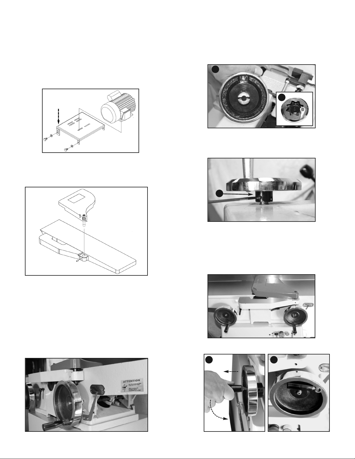
1. Using a hoist or with the help of appropriate number of
people, lift the jointer bed onto the base. Fig. 1
2. Align the 3 bolt holes of the jointer bed with the 3 holes
on the base.
3. Secure the jointer bed to the base, using 3 mounting
bolts with lock washers B from inside the cabinet into
the bottom of the jointer bed. Fig. 2
Note: Only hand-tighten the bolts for now. Final
tightening will be done after the pulley alignment.
Fig. 1
MOUNTING JOINTER TO BASE
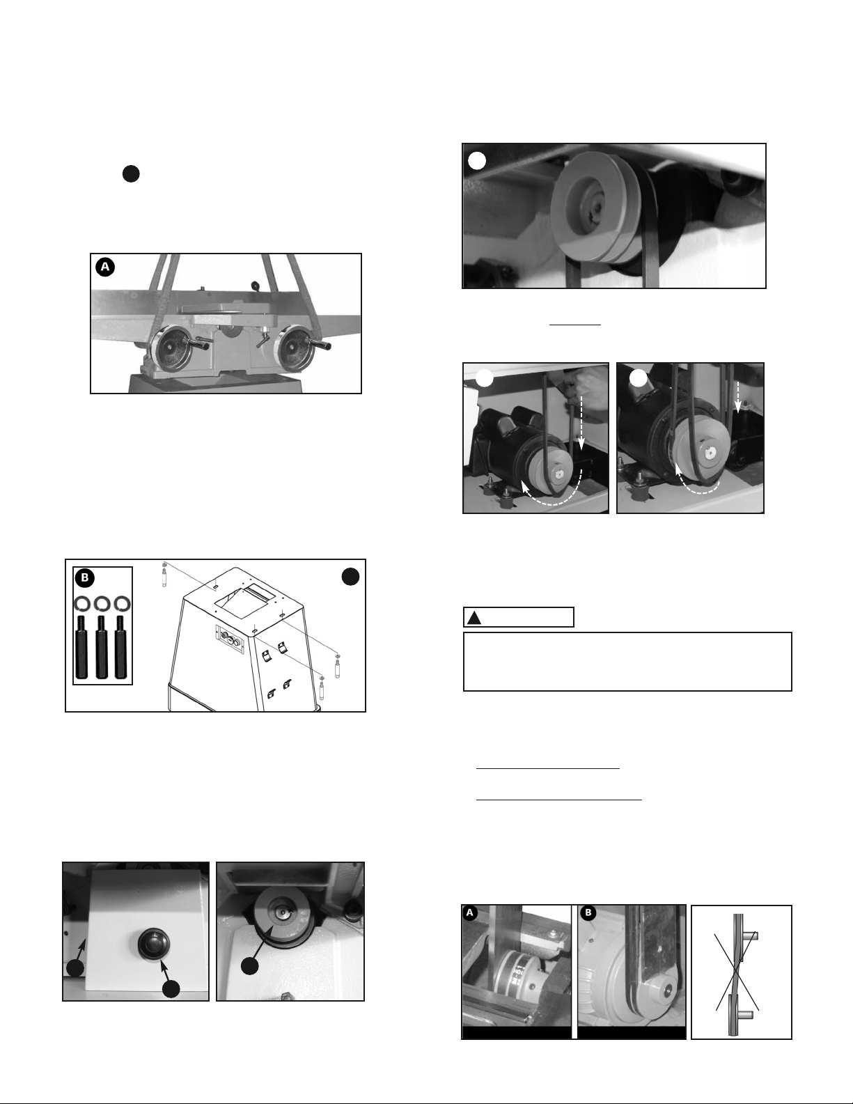
INSTA ING THE V-BE T
1. oosen and remove knob A, then remove the upper
pulley guard Bto get access to the upper pulley C.
Fig. 3
CAUTION
!
2. Install a V-belt in the groove on the cutterhead pulley D.
Fig. 4
3. Fit and hold a portion Eof the opposite end of the
belt into the corresponding groove on the motor
pulley. Fig. 5
4. Using both hands, carefully pull down on the belt to
Rotate the pulleys and allow the belt to sit itself in
the groove.
5. Repeat step 2 to install the second belt F. Fig. 5
Fig. 3
Fig. 2
Fig. 4
Fig. 5
Pull slowly – Keep your lower hand far enough
above the motor pulley to avoid pinching hand
between the belt and the pulley.
PU EY A IGNMENT
1. Hold a straight edge flush to the face of the pulleys
to check pulley parallel alignment. Fig. 6A + 6B
2. If the pulleys are aligned: fully tighten the bolts that
secure the jointer to the base .
3. If the pulleys are not aligned: move the position of the
jointer bed on the base to obtain pulley alignment, then
tighten the 3 mounting bolts.
NOTE: If pulley alignment still cannot be obtained, slide the
motor axially by loosening the motor rubber bushings.
oosen the nuts from under the motor baseplate, move the
motor to align pulleys, then carefully re-tighten the hex nuts.
Fig. 6A Fig. 6B
UPPER PU EY OWER PU EY
C
A
C
B
D
E F
S
Page 12
CHECK BE T TENSION
1. The belt should not deflect more than ½’’ (13 mm)
when squeezed at its midpoint.
2. If needed, tighten the belt by loosening the 4 motor
mounting bolts and applying a downward pressure
on the bracket then re-tighten the bolts. Fig. 7
NOTE: When tightening the belt, pay attention not to
undo the pulley alignment. After re-tightening the
bolts, check the alignment and re-adjust if necessary.
Fig. 7
INSTA CUTTERHEAD GUARD
1. Orient guard in proper position and insert post into
hole in table. Tighten set screw A. Fig. 8
3. Test tension by pulling back on the guard to bring it
away from the table and release.
4. Check that the guard return completely over the
cutterhead and fast enough. If it does not, hold the
tension adjustment knob, remove the guard, add
another ½ turn to knob and re-install the guard.
5. Test the tension again and repeat step 4 until
adequate tension is obtained.
6. To secure the guard in place, tighten the screw
removed in step 1. Fig. 9
INSTA THE FENCE AND TAB E
HEIGHT ADJUSTMENT HANDWHEE S
1. Fit the fence adjustment handwheel (smallest one) A
on the shaft on the rear fence bracket. Align
the slot in the handwheel with the spring pin
on the shaft. Fig. 10
2. Using 3mm Allen key, tighten the set screw on the
shaft Cto secure the handwheel. Fig. 11
3. Repeat above steps with the 2 big handwheels on
the shafts at the front of the jointer. Fig. 12
Note: The table height adjustment handwheels have flip up
handles. This minimizes the obstruction the handwheel
may cause during jointing operations. Fig. 13
Push down while
re-tightening bolts
Fig. 8
Fig. 9
Fig. 10
Fig. 11
Fig. 12
Fig. 13
B
A
C
1 2
Page 13
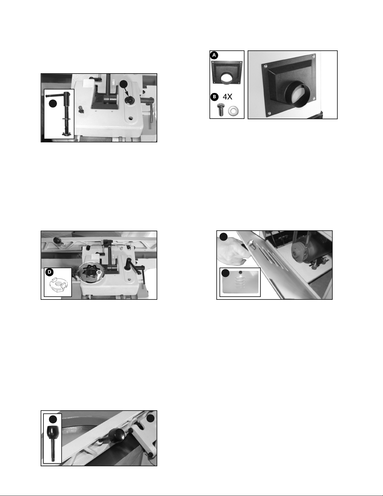
RE-POSITION THE FENCE OCKING
EVER
1. For shipping purposes, the fence locking lever is
installed upside down. Remove the lock nut Aand
the fence locking lever B and the flat washer. Fig. 14
2. Re-install the locking lever with flat washer on top
as shown in Fig. 15 and tighten the lock nut.
The lock nut must be oriented as shown in D.
Fig. 14
Fig. 15
INSTA THE FENCE TI T EVER
1. Thread the knob on the tilt lever A. Fig. 16
2. Screw the tilt fence lever into the threaded hole
in the fence.
Fig. 16
INSTA THE DUST PORT
Install the dust port to the left side of the base using
4 small Phillips screws with small flat washers. Fig. 17
Fig. 17
INSTA THE BASE DOOR
Attach the base door A to the base as shown. Fig. 18
Fig. 18
A
B
B
B
A
A

Page 14
OUTFEED TAB E ADJUSTMENT
The outfeed table must be EXACT Y level with the
knives when they are at their highest point of revolution.
The height of the outfeed table should be checked and
adjusted prior to first use and alsoperiodically to compen-
sate for knife wear and upon knife replacement.
1. Make sure the jointer is disconnected from
the power source.
2. To ease the procedure, you can remove the
cutterhead guard and the fence.
3. Set a straightedge onto the outfeed table so that it sits
over the cutterhead but does not close the gap between
the tables and touch the infeed table. Fig. 23
4. Turn the upper pulley by hand, until any one of
the knives is at it’s highest point.
5. oosen the table locking lever B. Fig. 24
6. Using the handwheel (C), adjust the outfeed table
height so the knife just barely touches the
straightedge.
7. Re-tighten the locking lever Bto secure the
outfeed table in position.
WARNING
!
MAKE CERTAIN THAT THE MACHINE IS
DISCONNECTED FROM THE POWER SOURCE
Fig. 24
INFEED TAB E ADJUSTMENT
The depth of cut is reached by raising or lowering
the infeed table. Fig. 25
1. oosen the table height lock lever (A). Fig. 26
2. Pull and hold back the 1/8’’ depth stop lock pin B.
Fig. 27
3. Using the handwheel (C), adjust the table height
to the desired depth of cut and release the 1/8’’
depth stop lock pin. Re-tighten locking lever (A)
to secure the table in position.
WARNING
!
THE MAXIMUM DEPTH OF CUT FOR ONE PASS
IS 1/8’’ . NEVER ATTEMPT TO REMOVE MORE
MATERIA THAN 1/8’’ IN ANY SING E PASS.
Fig. 25
WORKPIECE
DEPTH OF CUT
Fig. 26
Fig. 27
C
B
A
C
REAR VIEW
IMPORTANT ! Never adjust the table height with the lock-pin
engaged as this will break the pin.
B
Fig. 23
OUT-FEED
(left table)
IN-FEED
(right table)
ADJUSTMENTS

Page 15
ADJUST FENCE AND
POSITIVE STOPS
The fence on this jointer is equipped with positive
stops at specific pre-set angles.
They should be checked periodically and re-set
if necessary.
1. To move the fence front to back, loosen
locking lever (A). Fig. 29
2. Position the fence over the cutterhead as needed.
3. Re-tighten locking lever (A).
4. To tilt the fence, loosen locking lever (B).
5. Set the fence 45° inward or 45° outward.
6. Re-tighten locking lever (B) .
CHECK/ADJUST DEPTH OF CUT
INDICATOR
The depth of cut indicator was set at the factory to read “0” when
the infeed table is exactly at the same height as the outfeed
table. It should be checked prior to first use and from time to time.
1. With a straight edge, adjust the infeed table
at same height as the outfeed table.
2. If needed, loosen the 2 screws Cand adjust the
pointer to the “0” point on the scale D, then
re-tighten the screws. Fig. 28
WARNING
!
MAKE CERTAIN THAT THE MACHINE IS
DISCONNECTED FROM THE POWER SOURCE
Fig. 28
Fig. 30
1. To set the 45° outward fence stop, use a
combination or machinist square and set the
fence to 45° outward. Fig. 31
2. oosen the jam nut (H) on the 45° outward
fence stop bolt.
3. Adjust the 45° outward fence stop bolt (I) until
it makes contact with the back of the fence.
4. Re-tighten the jam nut.
Fig. 31
Fig. 32
1. To set the 90° fence stop, use a combination
or a machinist square (C). Fig. 30
2. Flip the 90° stop into position (D).
3. oosen the jam nut (E) on the 90° fence stop bolt.
4. Adjust the 90° fence stop bolt (F) until it makes
contact with the 90° stop.
5. Re-tighten the jam nut.
Fig. 29
1. To set the 45° inward fence stop, use a 45° combination
or machinist square and set thefence to 45° inward (J).
Fig. 32
2. oosen the jam nut (K).
3. Adjust the 45° inward fence stop nut ( ) until
it makes contact with the 45° inward stop (M).
4. Re-tighten the jam nut.
D
C
A
B
C
E
F
D
G
I
H
J
K
M
Page 16
Turn the power switch “OFF” and unplug the power
cord from its power source prior to any maintenance.
WARNING
!
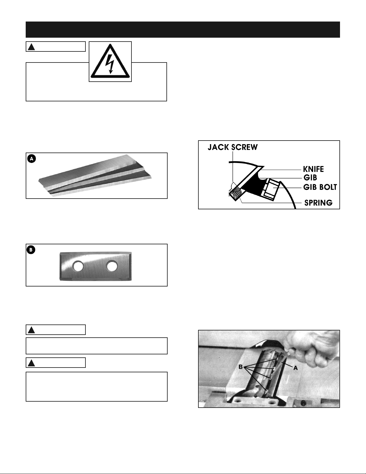
CUTTERHEAD KNIVES
MODE 30-300 S3:
There are 3 knives (A) installed in the cutterhead
at the factory. With usage and time, they will
require replacement. To maintain even knife wear,
replace all 3 knives at the same time.
MODE 30-300H:
There are 16 reversible carbide inserts (B) installed
in the helical cutterhead at the factory. With usage
and time, they will require replacement. To maintain
even insert wear, always reverse or replace all 16
inserts at the same time.
Fig. 29
KNIFE SETTING OR REP ACEMENT
To perform this task correctly, all components
(knives, screws, bars and cutterhead) need to be
thoroughly clean and free of any debris or pitch.
MODE 30-300 S3:
Properly setting all 3 knives is essential to obtain
accurate work results. Knives will also last longer and
will keep their sharpness longer by equally sharing
the cutting workload.
WARNING
!
WARNING
!
MAKE CERTAIN THAT THE MACHINE IS
DISCONNECTED FROM THE POWER SOURCE
BE EXTREME Y CAREFU THAT YOUR HANDS
DO NOT COME IN CONTACT WITH THE KNIVES.
THE KNIVES ARE VERY SHARP. WEAR PROTECTIVE
G OVES WHEN HAND ING THE KNIVES.
To obtain the best adjustment results of the knives, it
is imperative to number the knives and grooves on
the cutterhead. With a permanent felt pen, across the
groove and over the knife, draw 1 line for #1 knife,
2 lines for #2 knife and 3 for the #3 knife. This will
enable you to go back and forth from one knife to the
other to make fine adjustments and be certain that
all knives were tightened properly.
The straight knife cutterhead offers 2 methods
of adjustment: springs and jack screws (Fig. 29).
This provides you with 2 options for setting the knives,
so you can decide which method works best for you.
1. Turn off and disconnect the jointer from power
source.
2. To have full access to the cutterhead and knives,
remove the cutterhead guard.
3. Remove the fence to have access to the upper
pulley, so you can rotate the cutterhead to
access all of the knives.
4. Using a wrench, choose a first knife and loosen
(but do not remove) all the gib bolts B (Fig. 30).
Start in the center and alternate sides. If replacing,
loosen the bolts until the knife can be removed
and install the new knife.
Fig. 30
MAINTENANCE
Page 17
Fig. 31
Fig. 32
Fig. 33
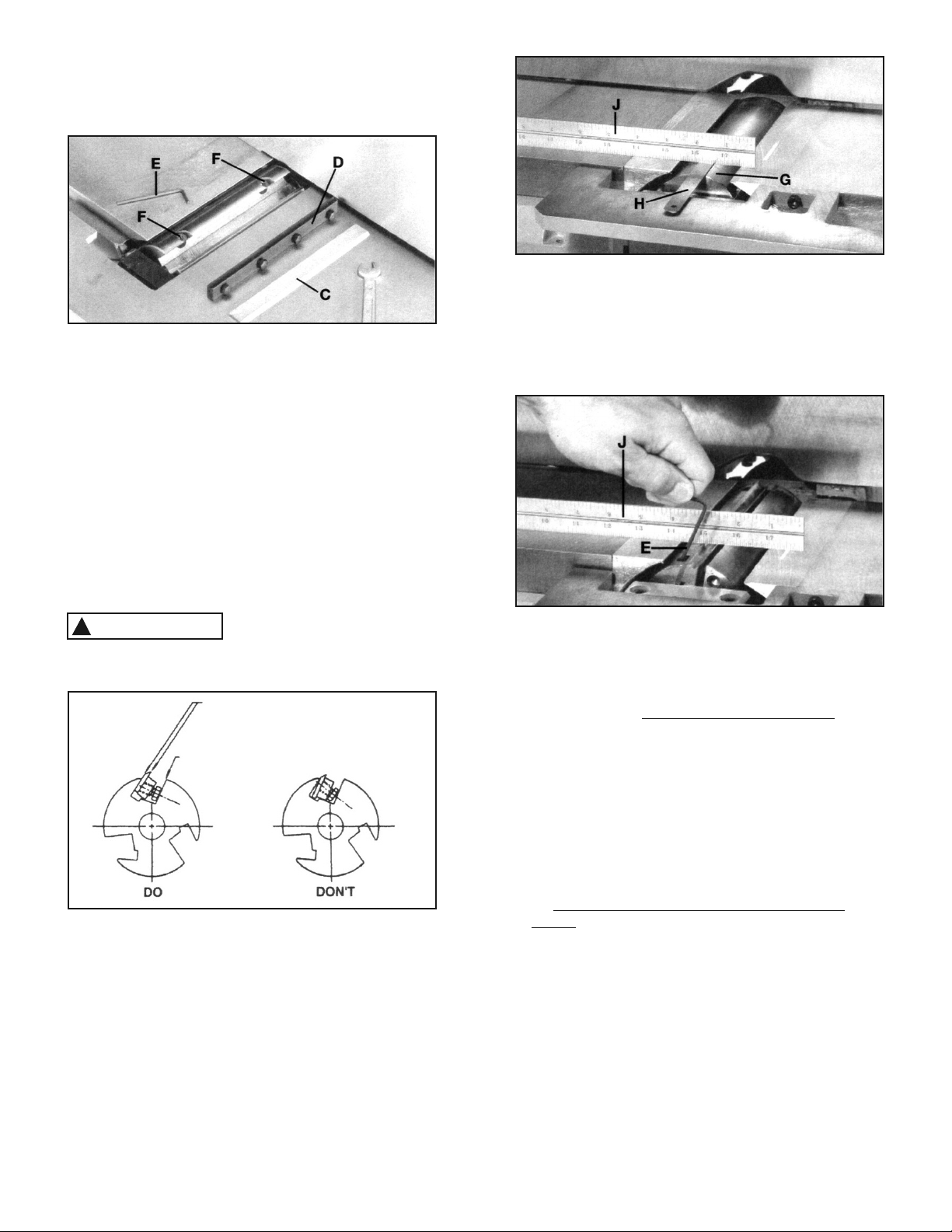
5. Fig. 31 shows the knife C and the knife locking
bar D removed from the cutterhead. Remove
the remaining two knives and locking bars, in the
same manner.
6. Using wrench E Fig. 31, lower the two knife
adjustment blocks to the bottom of the cutterhead
by turning screws Fcounterclockwise in all three
slots of the cutterhead.
7. Before assembling knives, make certain the knives,
the locking bars and the cutterhead are thoroughly
clean and free of gum and pitch.
8. Place the knife locking bars Dand knives C Fig. 31
into each slot in the cutterhead. Turn each screw B
counterclockwise just enough to hold the knife
in position. Replace the remaining two knives in the
same manner. Be careful, knives are very sharp.
WARNING
!
KNIVES MUST BE INSTA ED CORRECT Y AS
SHOWN IN FIG. 32 .
Mating surfaces of cutterhead to blade and blade
to bar to be tight and parallel.
Face of screw and face of cutterhead
to be parallel.
9. The knives are adjusted correctly when the cutting
edge of the knife extends out 0.015’’ from the
cutterhead diameter.
10. Carefully rotate the cutterhead G Fig. 33, until the
round portion of the cutterhead is on top as shown.
11. Place a 0.015’’ feeler gauge H Fig. 33, on the
cutterhead and using a straightedge Jon the outfeed
table, adjust the height of the outfeed table until it is
0.015’’ above the cutterhead diameter, as shown.
12. ock the outfeed table in position and remove the
feeler gauge.
13. ower the infeed table and place a straightedge J
Fig. 34 on the outfeed table, extending over the
cutterhead as shown.
14.a-) If you choose the jack screws to set the knife
height:
Rotate the cutterhead by hand until the knife is at
its highest point at each end of the cutterhead. To
raise the knife, use the wrench E Fig. 34, and turn
jack screw clockwise until the knife just touches the
straightedge J on each end and center of the
cutterhead when the knife is at its highest point.
When you are certain the knife is adjusted properly,
tighten the four locking screws B Fig. 30 by turning
them counterclockwise.
Repeat for the two other knives.
14.b). If you choose the springs to set the knife
height:
Push the knife down so the edge of the knife is
barely touching the straightedge (Fig. 34) . Hold
the knife down and tighten the bolts B Fig. 30
to secure the knife in place, at each end and in
the center of the cutterhead when the knife is
at its highest point.
Repeat for the 2 other knives.
Fig. 34
Page 18
15. Re-check the height setting on all knives and
re-set if necessary.
16. Replace the fence and the cutterhead guard
and set the infeed table height. Do not touch
the outfeed table adjustments.
WARNING
!
MAKE CERTAIN THAT A KNIVES ARE
SECURE Y FASTENED IN THE CUTTERHEAD
BEFORE TURNING ON THE POWER.
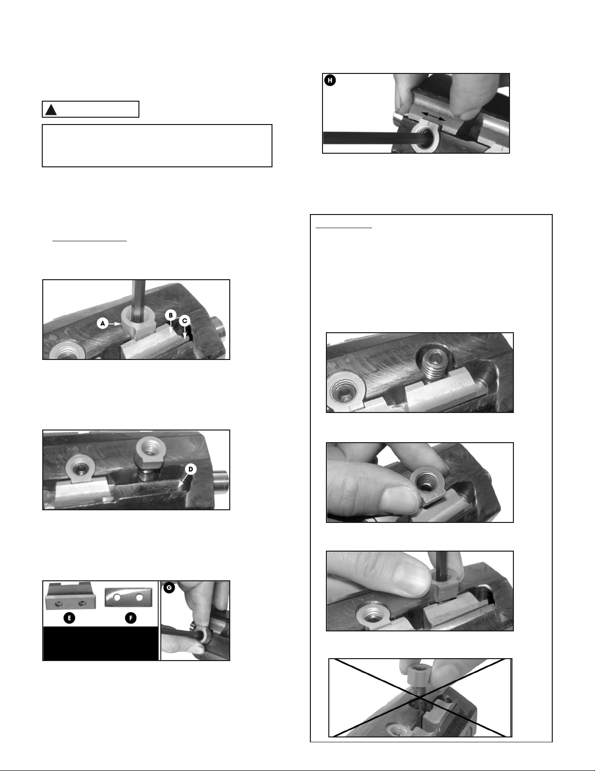
HE ICA CUTTERHEAD INSERT
REVERSA / REP ACEMENT
MODE 30-300 HS3:
1. Using one of the supplied Allen keys, loosen
but do not remove the nut and screw Aand
remove the knife holder/chip breaker Band
the insert C. (Fig. 35)
2. Thouroughly clean the housing Dbefore reinstal-
ling the knife holder/chip breaker and insert.
(Fig. 36)
3. Thouroughly clean the knife holder/chip breakers E
and inserts Fusing a lacquer thinner and a small
brush. (Fig. 37)
4. Reverse or replace the insert and re-install it along
with the knife holder/chip breaker into the slot and
partially retighten the nut and screw G.
Fig. 35
Fig. 36
Fig. 37
Important! To prevent knife height
discrepancies, the knife holders /
chip breakers and inserts must be
clean and free of debris.
5. Center the knife holder/chip breaker with the flat
edge of the nut Hand fully tighten the nut and
screw. (Fig. 38)
6. Repeat with all the other inserts.
Fig. 38
IMPORTANT:
DO NOT REMOVE the nut and screw that secure the
knife holder/chip breaker, ON Y OOSEN. If the nut
and screw have to be replaced or if they have been
removed, follow instructions below to make sure the
knife holder/chip breakers are all secured at the same
height into the cutterhead.
1. Place the screw in the threaded hole but do not start
tightening it yet.
2. Place the nut on top of the screw but do not start
tightening it yet.
3. Hold the nut with your fingers and tighten the screw.
This will tighten both the screw and the nut simultaneously.
Do not thread the nut onto the screw before tightening
the screw into the threaded hole in the cutterhead.

Page 19
To start the jointer, push on the green ‘START’
button B (Fig. 40). Wait for the cutterhead to reach
full speed before starting jointing.
To stop the jointer, push on the red ‘STOP’ button C
and wait for the cutterhead to come to a complete stop.
The red ‘STOP’ button is a mushroom type
pushbutton that locks into position when pressed.
The jointer can only be started by turning the button
D clockwise so it pops out and releases the stop
button.
ADJUSTING THE GIBS
The table gibs allow elimination of excessive play when
raising/lowering the tables. When properly adjusted, this
will allow for a smooth and easy table height adjustment.
Avoid this operation unless critical !
Adjusting gibs on a jointer must only be performed
by a knowledgeable machinery repair technician.
Inadequate adjustment could cause irreversible
damage to your jointer.
We recommend taking an appointment with a certified
repair center to perform this operation.
MAGNETIC SAFETY SWITCH
This jointer is equipped with a magnetic safety
switch for superior user protection. Should
there be a power outage during operation, the
jointer will not start unexpectedly when the power
resumes.
The magnetic switch components are located inside
the base cabinet.
The remote start and stop buttons are conveniently
located within easy reach of the user in front of the
jointer. Fig. 39
CB
Fig. 39
Fig. 40
D
MOTOR
MAGNETIC SWITCH
CONTROL PANEL
BLACK
WHITE
BLACK
WHITE
GREEN
BLACK
WHITE
WHITE
GREEN
BLACK
BLACK
BLACK
WHITE
WHITE
RED
RED
GREEN
GREEN
GREEN
GREEN
GROUND
STOP
13 14 2122 13 14
MODE 30-300E ECTRICA CIRCUIT

Page 20
Motor and Machine Operation
PROB EM IKE Y CAUSE(S) SO UTION
Motor will not start. 1. ow voltage.
2. Open circuit in motor or loose
connections.
1. Check power line for proper voltage.
2. Inspect all lead connections on motor for
loose or open connections.
Fuses or circuit
breakers blow.
1. Short circuit in line cord or plug. 1. Repair or replace cord or plug for
damaged insulation and shorted wires.
Motor fails to develop
full power (output of
motor decreases
in voltage at motor
terminals).
1. Power supply circuit overloaded with lights,
appliances, and other motors.
2. Undersized wires or circuits too long.
1. Reduce load on circuit.
2. Increase wire sizes or reduce length of the
circuit.
Motor overheats. 1. Motor overloaded during operation.
2. Air circulation through the motor restricted.
1. Reduce load on motor; take lighter cuts.
2. Clean out motor to provide normal
air circulation.
Motor stalls or shuts
off during a cut.
1. Motor overloaded during operation.
2. Short circuit in motor or loose connections.
3. Circuit breaker tripped.
1. Reduce load on motor; take lighter cuts.
2. Repair or replace connections on motor for
loose or shorted terminals or worn
insulation.
3. Install correct circuit breaker; reduce
number of machines running on that circuit
(circuit overload).
Blade slows when
cutting or makes a
squealing noise,
especially on start-up.
1. V-belt loose.
2. V-belt worn out.
1. Tighten V-belt.
2. Replace V-belt.
oud, repetitious noise
coming from machine.
1. Pulley setscrews or keys are missing or
loose.
2. Motor fan is hitting the cover.
3. V-belts are damaged.
1. Inspect keys and setscrews. Replace or
tighten if necessary.
2. Adjust fan cover mounting position, tighten
fan, or shim fan cover.
3. Replace V-belts.
Vibration when
running or cutting.
1. oose or damaged knife.
2. Damaged V-belt.
3. Worn cutterhead bearings.
1. Tighten or replace knife.
2. Replace.
3. Check/replace cutterhead bearings.
Table
PROB EM IKE Y CAUSE(S) SO UTION
Tables are hard to adjust. 1. Table lock is engaged or partially engaged. 1. Completely loosen the table lock.
ADJUSTMENTS
This manual suits for next models
3
Table of contents


