stellar labs Model 10628 User manual

!$%%"!($$ '#&!$(#%$
)
Stellar Industries, Inc.
190 State Street
O Box 169
Garner, IA 50438
800-321-3741
Fax: 641-923-2811
www.stellarindustries.com Last Revision: 04/17/13
Subject to Change without Notification.
© 2013 Stellar ndustries, nc.
®
TM

10628 Manual Revisions
Date of Revision
September 15th, 2011
Description of Revision
New Flip Sheave Design mplemented. Updated Extention
Boom, Mast, Cable & Hook Assembly Drawings.
Section Revised
Chapter 2: nstallation
Chapter 3: Assembly
Drawings

For Technical Questions, Information, arts, or Warranty, Call Toll-Free at
800-321-3741
Hours: Monday - Friday, 8:00 a.m. - 5:00 p.m. CST
Or email at the following addresses:
Technical Questions, and Information [email protected]
Warranty Information [email protected]
Table of Contents
Table of Contents
Chapter 1 - Specifications ......................................................................1
Capacity Chart - Decal PN 54496....................................................2
Chapter 2 - Installation ...........................................................................3
nstallation Overview ..........................................................................4
Control Kit - PN 52870 .........................................................................5
Control Kit (Non-Boost) - PN 58291 ...................................................6
Hydraulic Kit - PN 52264 .....................................................................7
Valve Bank - PN 52265........................................................................8
Hydraulic nstallation ..........................................................................9
Winch Case Drain nstallation .........................................................10
Hydraulic System...............................................................................11
Stability Procedure............................................................................12
Decal Kit Placement - PN 54762 .....................................................13
Chapter 3 - Assembly Drawings ..........................................................15
Base Assembly - PN 18027 ...............................................................15
Mast Assembly - PN 52488 ...............................................................16
Main Boom - PN 52869 .....................................................................17
Extension Boom Assembly - PN 61817 ............................................18
Extension Boom Assembly - PN 61817 (Expanded) ......................19
Main Cylinder Assembly - PN 43839 ...............................................20
Extension Cylinder Assembly - PN 28856 ........................................21
Cable & Hook Assembly - PN 55898...............................................22
CDT™ Radio Transmitter Assembly - PN 56647..............................23
Chapter 4 - Replacement arts ...........................................................25

10628 O ner’s Manual

Specifications
Chapter 1 - Specifications
Model 10628 Crane
S ECIFICATION SHEET
Crane Rating: 60,000 ft-lbs (8.29 TM)
Standard Boom Length: 12’ 6” (3.81 m) from CL of Crane
Boom Extension: 1st stage: Hydraulic 96" (243.8 cm)
2nd stage: Hydraulic 96" (243.8 cm)
Maximum Horizontal Reach: 28’ 6” (8.69 m) from CL of Crane
Maximum Vertical Lift: 30’ 4” (9.24 m)
(from crane base)
Boom Elevation: -5 to +80 degrees
Stowed Height: 35” (88.9 cm)
(crane only)
Mounting Space Required: 20” x 21” (50.8 x 53.3 cm)
Approximate Crane Weight: 2900 lbs (1315 kg)
Controls: Radio control standard for all functions.
Winch Specifications
Rope Diameter: 7/16" (1.11 cm)
Line pull speed: 60 ft/min (18.29 m/min)
Max. single part line: 5000 lbs (2268 kg)
Max. double part line: 10,000 lbs (4535 kg)
Rotation: 400 degree power
(worm gear)
Lifting Capacities: 4875 lbs @ 12’ 6” (2210 kg @ 3.81 m)
2950 lbs @ 20’6” (1335 kg @ 6.25 m)
2115 lbs @ 28’ 6” (960 kg @ 8.69 m)
Power Supply Required: PTO & Pump
(8 gpm @ 3000 psi)
(30.3 lpm @ 207 bar)
*Subject to change without notification

10628 O ner’s Manual
Weight of load handling devices are
part of the load lifted and must be
deducted from the capacity.
Maximum 1 - part line capacity is
5000lbs (2270kg). For greater
loads, use 2 - part line.
PN 54496
Reach in Feet/Meters
Capacity in Pounds/Kilograms
15º
30º
80º
75º
60º
45º
10000 lbs
4535 kg
10000 lbs
4535 kg 10000 lbs
4535 kg
10000 lbs
4535 kg
8760 lbs
3975 kg
6735 lbs
3055 kg
7945 lbs
3600 kg
5425 lbs
2460 kg
6400 lbs
2900 kg
4980 lbs
2260 kg
5875 lbs
2660 kg
4875 lbs
2210 kg
5750 lbs
2605 kg
2950 lbs
1335 kg
3480 lbs
1575 kg
2115 lbs
960 kg
2495 lbs
1130 kg
7405 lbs
3355 kg
8735 lbs
3960 kg
4040 lbs
1830 kg
4765 lbs
2160 kg
2970 lbs
1345 kg
3505 lbs
1585 kg
2410 lbs
1095 kg
2840 lbs
1285 kg
2170 lbs
985 kg
2560 lbs
1160 kg
3035 lbs
1375 kg
3580 lbs
1620 kg
3335 lbs
1510 kg
3935 lbs
1780 kg
4120 lbs
1870 kg
4860 lbs
2205 kg
5530 lbs
2505 kg
6525 lbs
2955 kg
9950 lbs
4515kg
10000 lbs
4535 kg
10000 lbs
4535 kg
0'
0 m
3'
.914m
6'
1.83 m
9'
2.74 m
12'6”
3.81 m
28'6”
8.69 m
20'6”
6.25 m
12'
3.66 m
3'
.914
6'
1.83 m
9'
2.74 m
15'
4.57 m
18'
5.49 m
21'
6.40 m
24'
7.01 m
27'
8.23 m
30' 4”
9.25 m
Boost
(If Equipped)
Standard
Capacity Chart - Decal N 54496

Installation
Chapter 2 - Installation
General Installation
This chapter is designed to serve as a
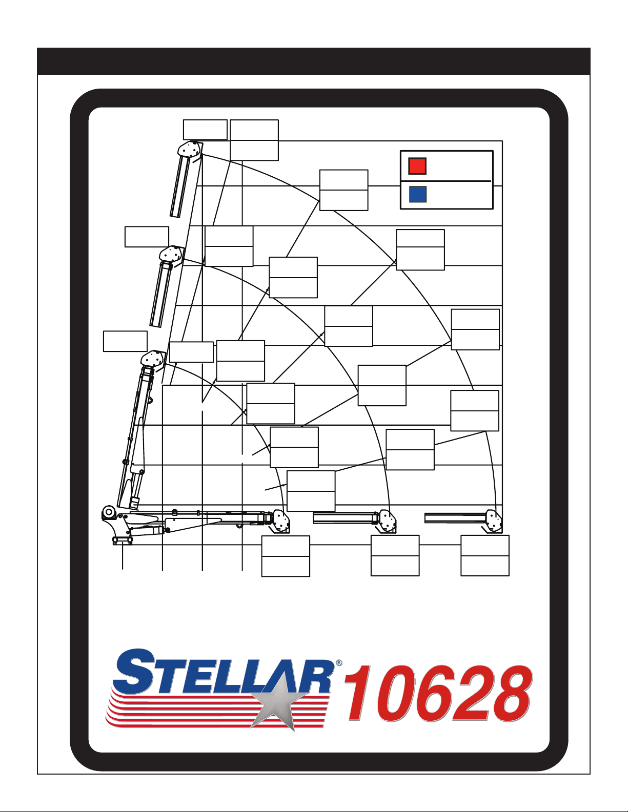
general guide for the installation of a Stellar
10628 Telescopic Crane on a Stellar Service
Body. Each installation is considered unique
so certain portions of this chapter may or
may not apply to your direct application. f
a question should arise during the installation
process, please contact Stellar Customer
Service at (800) 321 3741.
This crane is designed for use with a Stellar
Service Body installed on a vehicle that
meets the minimum chassis requirements of
the crane. t is the installer’s responsibility to
assure that the crane is mounted on a
platform that will support the maximum
crane rating of this crane.
Notice:
PTO and Pump installation instructions are
provided by the corresponding
manufacturers. For more information on
which PTO and Pump fit your application,
please contact your local Stellar Distributor
or Stellar Customer Service.
Installation Notice
According to Federal Law (49 cfr part 571),
each final-stage manufacturer shall
complete the vehicle in such a manner that
it conforms to the standards in effect on the
date of manufacture of the incomplete
vehicle, the date of final completion, or a
date between those two dates. This
requirement shall, however, be superseded
by any conflicting provisions of a standard
that applies by its terms to vehicles
manufactured in two or more stages.
Therefore, the installer of Stellar cranes and
bodies is considered one of the
manufacturers of the vehicle. As such a
manufacturer, the installer is responsible for
compliance with all applicable federal and
state regulations. They are required to
certify that the vehicle is in compliance with
the Federal Motor Vehicle Safety Standards
and other regulations issued under the
National Traffic and Motor Vehicle Safety
Act.
Please reference the Code of Federal
Regulations, title 49 - Transportation, Volume
5 (400-999), for further information, or visit
http://www.gpoaccess.gov/nara/index.html
for the full text of Code of Federal
Regulations.
Notice: Read this age Before Installation of the Crane
Important: When installing welder units to the service
bodies, it is highly recommended that a surge
protector is installed on the chassis batteries to protect
the crane radio receiver, wiring and other electronic
devices from an unexpected electrical spike or surge.
Failure to do so could result in extensive damage to
the service body and crane electrical circuit.

10628 O ner’s Manual
1
2
NOTE:
STABILITY DECAL P/N 16881
IS PART OF THIS KIT
2.38
6.88
7.38
7.38
6.00
.YTQNOITPIRCSEDTRAPMETI
1 5199 CAP SCR 1.00X8X3.00 HHGR8 ZY6
2 6538 WASHER 1.00 SAE FLAT YELLOW GR86
Front Motor
14.75
PN 13539
13.75
14.75
1.063
6 Places
WARNING!
The use of this crane on a
body not capable of handling
the loads imposed on it may
result in serious injury or
death.
Installation Overview
1. Determine that the mounting location for the 10628 crane is at least 20” x 21” (50.8 x 50.8 cm).
2. Use the detail below to drill 1.06” diameter holes into the mounting plate. Run tap on the threads of the
base to be sure they are clean.
3. Use a crane or lifting device capable of lifting the weight of the Stellar crane. The Stellar 10628 weighs
approximately 2900 lbs (1315 kg). Note: cranes are shipped with rotation positioned at 200 degrees of 400
degree system. This will allow for easy installation of the crane and permanent connection of all hydraulic
and electrical components prior to repositioning into the crane saddle.
4. Connect straps or chain from the lifting device to the lifting rings on the Stellar 10628.
5. Use six (6) 3” x 1” #8 bolts and six (6) #8 flat washers.
6. nstall a washer on each bolt.
7. Apply Loctite Thread locker #277 to the bolts.
8. Using the lifting device, lower the Stellar 10628 just above the crane compartment and start the bolts.
Have someone assist in leveling the crane. Note: the rotation motor should be to the door side of crane
compartment and the boom should be extended back over the rear bumper.
9. Secure the crane using the mounting hardware provided. Note: longer or shorter cap screws may be
required – recommended thread engagement into crane base is 1.75” – use grade 8, zinc plated cap
screws only.
10. Torque the cap screws to 680 ft-lbs.
11. Remove supporting crane.
12. Hook-up hydraulics and electrical using the schematics provided in this chapter. Note: If questions
should arise during any portion of this installation, please contact Stellar Customer Service at (800) 321-
3741.

Installation
PN 52870
FB
D
ECA
PD1
PD2
ROT
ROT
PROPORTIONAL
CW CCW
VALVE
MAIN
DOWN
EXTENSION
RETRACT
MAIN
UP
EXTENSION
EXTEND
WINCH
DOWN
WINCH
UP
AB
5
MAIN CYL
MANIFOLD
PD1
PD2
POWER
PWR UNIT SIGNAL
GROUND
ENG START
ENG STOP
CPRSR ON/OFF
BASE END
ROD END
B
AB
AB
AB
AB
A
ABABA B AB
INCLINOMETER
4
2
3
A2B
SWITCH
SPEED CTRL OUTPUT 1
PWR ON DEMAND MODE
SPEED CTRL OUTPUT 2
ON / OFF MODE
67
5 6 7
CORD REEL
*WIRING OPTIONS FOR REMOTE CONTROL OF ENGINE SPEED:
1. POWER ON DEMAND (POD) MODE- ALLOWS AUTOMATIC
SWITCHING OF HIGH IDLE BASED ON CRANE OPERATION.
- OR -
2. ON/OFF MODE - ALLOWS MANUAL SELECTION OF HIGH IDLE.
Control Kit - N 52870

10628 O ner’s Manual
PN 58291
FB
D
ECA
PD1
PD2
ROT
ROT
PROPORTIONAL
CW CCW
VALVE
MAIN
DOWN
EXTENSION
RETRACT
MAIN
UP
EXTENSION
EXTEND
WINCH
DOWN
WINCH
UP
AB
5
MAIN CYL
MANIFOLD
PD1
PD2
POWER
PWR UNIT SIGNAL
GROUND
ENG START
ENG STOP
CPRSR ON/OFF
BASE END
ROD END
B
AB
AB
AB
AB
A
ABA B ABAB
INCLINOMETER
4
2
3
A2B
SWITCH
SPEED CTRL OUTPUT 1
PWR ON DEMAND MODE
SPEED CTRL OUTPUT 2
ON / OFF MODE
67
5 6 7
CORD REEL
* WIRING OPTIONS FOR REMOTE CONTROL OF ENGINE SPEED:
1. POWER ON DEMAND (POD) MODE- ALLOWS AUTOMATIC
SWITCHING OF HIGH IDLE BASED ON CRANE OPERATION.
- OR -
2. ON/OFF MODE - ALLOWS MANUAL SELECTION OF HIGH IDLE.
Control Kit (Non-Boost) - N 58291

Installation
NOTE: USE 32" OF HOSE PROTECTOR
P/N 17288 OVER THE ROTATION HOSES
NOTE: USE 12" OF HOSE PROTECTOR
P/N 17288 OVER THE 3 WINCH HOSES
PN 52264
Hydraulic Kit - N 52264

10628 O ner’s Manual
HYDRAULIC SCHEMATIC 4
3
1
4
3
4
3
2
PN 52265
YTQNOITPIRCSEDTRAPMETI
1 25367 RELIEF VALVE 24685/24690 1
25368 SEAL KIT 25367
2 24960 VALVE FLW CTRL PRP/JP04C3150N 0-8 1
25369 SEAL KIT 24960/25381
3 25371 VALVE SOLND 3 POS 4 WAY TAND G04571 4
25373 SEAL KIT 25371/25372
4 44532 COIL 12VDC DUETSCH CAP012H 9
Valve Bank - N 52265

Installation
Hydraulic Installation
1. After mounting, locate the pressure and return
lines. Note: Pressure line is 3/8” hose; Winch
Case Drain Line is 3/8” hose; Return line is 1/2”
hose. Hoses are terminated using swivel fittings.
2. Install hydraulic lines per diagram below. See
next page for Case Drain Installation. Note:
Stabilizer valve supplies oil to crane using the
Power Beyond feature.
3. Install hydraulic reservoir with return filter. Attach
pump pressure line to valve, return link to tank.
4. Fill system with hydraulic oil (See Stellar®
Lubrication Recommendations for fluid details).
(Blue)
Stabilizer Functions
Typical Stabilizer Valve
with Power Beyond Capabilities

10628 O ner’s Manual
Winch Case Drain Installation
Installing the winch case drain
1. The winch case drain must run directly to the reservoir to ensure no back pressure in the line.
2. Use 3/8” hydraulic hose and fittings rated for a minimum of 300 psi.
3.
4. Attach one end of the winch case drain to 3/8 swivel fitting located in step 3.
5. Route the winch case drain hose directly to the reservoir.
6. Connect the second end of the winch case drain to unshared fitting on the top of the reservoir as
shown in Fig 2.
Fig.1 Fig.2
Locate the winch case drain line at the bottom of the crane base as shown in Fig. 1 (Blue Hose).
Note: Both the main pressure and winch case drane line use a 3/8” swivel fitting. Verify the winch
case drain is attached to the hose that is connected to the winch motor.
(Blue)

Installation
Hydraulic System

10628 O ner’s Manual
Definition of Stability for the Stellar Telescopic Crane
roducts:
A truck is stable until the load cannot be lifted off
the ground with the winch, without tipping over the
truck. Every Stellar crane installed must be tested for
stability to determine the actual load capacity of
the final truck package. The actual test data must
be recorded and supplied with the truck at the time
of in-service and should be kept with the truck at all
times. The following procedure will test the truck
package for stability and will provide a stability
capacity chart. The load limit information shown on
the stability capacity chart is formulated on 85%
tipping.
Set Up:
1. Locate the truck on a test course in position for
loading and engage travel brakes.
2. Set stabilizers so that they make contact with firm,
level footing.
3. Operate the crane under partial load to assure
operator proficiency and proper machine
function.
4. Put the radio into Stability Test Mode:
A. Push the bottom four switches up and hold until
all lights come on (approximately 5 seconds.)
B. At this point ,the crane will have enough
capacity to handle the weight for the stability
test.
C. The radio will timeout of stability mode after 30
minutes or when the E-Stop button is pushed.
Note: The radio can only be put into stability mode
five times. After that, the radio would have to be
returned to Stellar to be reprogrammed to allow
additional stability testing. All other radio functions
will work properly even if stability mode is not avail-
able.
Test rocedure
1. Rotate the crane into Zone 1 position.
2. With the crane fully retracted and the boom
horizontal, winch the test weight off the ground.
Note: Keep weight within six inches of the ground
at all times.
3. Extend the boom outward until full extension has
been reached or until the truck becomes unstable
(Again, use the winch to keep the weight within six
inches of the ground.)
4. f the boom goes full extension without becoming
unstable, the crane is termed stable for this zone
and 100% can be written in the Zone 1 data box.
5. f the truck becomes unstable prior to going full
extension, retract the boom until the truck
becomes stable and measure the horizontal
reach in this position (center of rotation to boom
tip). This is the stable horizontal reach for this zone.
Stable horizontal reach divided by Maximum
horizontal reach multiplied by 100 equals the
percentage of rated capacity for this zone. Use
the following formula to determine the
percentage of rated capacity:
6. Record this number in the data box for Zone 1.
This is the revised capacity due to stability for this
zone.
7. Repeat this procedure for each zone until the
worksheet is completed.
8. This is the revised capacity based on stability of
this package.
10628 Stability Data
Max Horizontal Reach: 342” (From the center of
rotation to boom tip)
Boost Stability Test Weight: 2945 lbs.
Non-Boost Stability Test Weight: 2495 lbs.
Stability rocedure

Installation
Decal Kit lacement - N 54762
PN 54762 *USE THESE DECALS WITH BODY PACKAGE
**THESE DECALS NOT INCLUDED WITH THE DECAL KIT
1
2
®®
10628
ITEM
01
*04
02
*03
*05
*06
09
*07
*08
*10
*11
*12
*13
15
14
DECAL HOISTING PERSONNEL
DECAL STELLAR LOGO 6.5 x 18
DESCRIPTION
PART No.
52681
PART No.ITEM
QTY
*16
2
12451
DESCRIPTION QTY
1
DECAL ASME/ANSI B30.22/B30.5
DECAL GREASE WORM DRIVE BEARINGS
DECAL-ROTATION ALIGNMENT
C4545 DECAL-ELECTROCUTION 5x13
DECAL CAPACITY
DECAL 10628 IDENTIFICATION52687
54496
DECAL-DANGER
DECAL-DANGERC4540
C4544
DECAL MANUAL EXT12452
4
*19
*17
2
C5910
*18
2
C5911
DECAL-STELLAR 4x9.5
DECAL-STELLAR 2x4.5
C0568
1
*20
*21
1
4214
DECAL-DIESEL
DECAL-SERVICE
9188 DECAL-ROTATE/ GR EA SE
DECAL-DANGER
DECAL-ELECTROCUTION 2x2.754186
4189
DECAL-DANGER
DECAL-DANGER O.R.
4190
C4795
4188
1
24
22
1
12300
*23
1
C4541
DECAL-TWO BLOCKING
DECAL-CRANE STOWING
15171
1
25
26
2
15172
1
1
3
2
1
1
1
1
1
1
DECAL VB CONTROL MECH CRANE
DECAL STELLAR MADE IN THE USA
DECAL SNATCH BLOCK CAP 7 TON
DECAL WARNING OVERLOAD DEVICE
DECAL CAUTION STOW HOOK
52270
31
DECAL-ELECTROCUTION 4.5x7.5
DECAL-DANGER MOVING O.R.C5918
C1179
DECAL-ANGLE INDICATOR SS
DECAL ANGLE INDICATOR CS
D1197
D1196
27
2
24712
28
2
28256
35234
30**
1
29
1
56405
1
1
1
1
1
32 25159 DECAL WARNING MANUAL OVERRIDES 1
3
26
14,15
27
22
29
28
30
25
9
60
50
0
20
30
10
40
Angle Indicator
80
70
33
33 54588 DECAL CDT 2.00X2.00 2

10628 O ner’s Manual

Assembly Dra ings
10
8
7
1
6
2
3
4
9
GASKET SHOWN AS REFERENCE
14
12
10
11
5
.YTQNOITPIRCSEDTRAPMETI
1 11453 BEARING SWING DRIVE CAST BASE 66201
1EDILS0040283POTS245112
3C6069 MOTOR HYD ROSS MK080613AAAB1
4D1307 CAP SCR 0.50-13X1.25 SH2
5 44551PC GUARD TTB 6620 CRANE LZR1
6 13959 CAP SCR 1.00-8 X .63 PLASTIC2
2TALF52.0REHSAW04307
8 0479 CAP SCR 0.25-20X0.75 HHGR52
9 21151GASKETMOTOR 008-10056-11
10 D1345 FTG CPRSN 0.12NPT/0.25 TUBE2
11 D1810 TBE AIR SAEJ844 TYPE A .25 (RM)1
131.0EPIPRELPUOCGTF6522C21
28RGTALF05.0REHSAW0970D31
14 56589 ZERK 1/8 NPT STRAIGHT LONG THREAD 1
PN 18027
Base Assembly - N 18027
Chapter 3 - Assembly Drawings

10628 O ner’s Manual
.YTQNOITPIRCSEDTRAPMETI
112621/12601TSAM384341
227813 COLLAR 0.38X0.75X0.38 UHMW2
3C5902 WASHER 0.63 SAE FLAT YELLOW GR818
4D1034 CAP SCR 0.63-11X3.00 HHGR8 RED PATCH14
5 0343 WASHER 0.31 USS FLAT ZINC4
6C0933 CAP SCR 0.31-18X4.50 HHGR52
7 0342 NUT 0.31-18 HHGR5 NYLOC 2
844533BUSHING HSG3235012S 2.00X0.75 4
9 11693 CAP SCR 0.63-11X1.75 HHGR8 4
10 52490 CAP SCR 6MMX30MM HH 8.8(GR5)4
11 57917 WINCH 5000 TH2CC00243 W/100 FT ROPE 1
12 52265 VB 4 SECT W/PROP STER8GPM DEUTSCH1
PN 52488
DO NOT GREASE
THESE BUSHINGS
12
1
3
4
11
3
9
75
2
5
6
8
10
Mast Assembly - N 52488
Table of contents
Popular Toy manuals by other brands

PIKO
PIKO H0 SmartMeasure Car instruction manual

Mega Bloks
Mega Bloks HELLO KITTY 10931 manual

Wen Sheng
Wen Sheng WS-B005 instruction manual

CNC Workshop
CNC Workshop MINIATURE SCENERY Shipping Container1 instructions

LGB Lehmann
LGB Lehmann 55016p instructions

Hobby-Lobby
Hobby-Lobby ESM1100 instruction manual

AeroWorks
AeroWorks 30cc BRAVATA ARF-QB Assembly manual

Bandits and Angels
Bandits and Angels TWT8376 Assembly instructions

LEGO
LEGO STAR WARS 9516 Building instructions

Faller
Faller SWEETS STALL AND BALLOON ARTIST manual

Spirit Halloween
Spirit Halloween Limb Ripper Easy-to-follow Instructions

Lionel
Lionel F3 A-B-A Diesel owner's manual