Steltronic API A065 Series User manual

API A065 series
Interfacing
Via Bowling/Switch pinsetters
(Wins/Focus Scoring Syste )
Steltronic S.p.A.
Via Artigianale 34, 25082 Botticino Sera Brescia - Italy
Tel: +39 030 2190811 ax: +39 030 2190798
http://www.steltronic.com
Worldwide Service: + 39 030 2190830
Email: servic[email protected]
US Steltronic: +1 (909) 287-0712
service.usa@steltronic.com

API A065 series Inter acing Via bowling (MC2)/Switch pinsetters
2
Index
General about A.P.I. A065 series pg. 03
Long cable installation pg. 04
A.P.I. A065 boards layout pg. 07
Connecting Bumpers, Glow, Bar- Maintenance call light pg. 09
Inter acing Via Bowling Pinsetters pg. 12
Switch pinsetter chassis Inter acing pg. 13
A.P.I. so tware settings (WINS SCORING) pg. 16
WINS Advanced Settings or Bumpers pg. 18
A.P.I. So tware update (WINS SCORING) pg. 19
A.P.I. So tware settings (FOCUS SCORING) pg. 20
A.P.I. Advanced Database Setting (FOCUS SCORING) pg. 22
A.P.I. So tware update (FOCUS SCORING) pg. 26

API A065 series Inter acing Via bowling (MC2)/Switch pinsetters
3
General about A.P.I. A065 Series
The A.P.I [Advanced Pinsetter Inter ace] is the latest Steltronic designed pinsetter inter ace; it has
two boards, which are contained in one box. One A.P.I. controls one or two pinsetters (one pair o
lane).
The CPU board is the “ logic “ part o the inter ace, it communicates with the lane computer via a
serial connection. The inter ace so tware is installed onto local EEPROM ( lash memory), this can be
updated via so tware rom the Front Desk. The pinsetter selection is made using dipswitches as well
as through so tware.
The I/O board constitutes the “physical inter ace” which changes depending on the type o pinsetter;
the model A065 series is a standard or vary pinsetter, included Via Bowling (MC2) and Switch
pinsetters
As all models o A.P.I. the A.p.i. modle A065 use the CAB-Y-CA0092 cable to inter ace and receive
power rom the lane computer.
General installation notes
• Position the A.P.I. inter ace near the pinsetter (example, on the curtain wall), keeping the
connectors on the way to acilitate the installation.
• Optional: Position a plastic conduit near the API, (about 4 x 2 cm or 1½ x 1 inches in size) to
run all cables through.
Max distance rom
A.P.I. to pinsetter
Score Input
connectors= 4,5
meters.

API A065 series Inter acing Via bowling (MC2)/Switch pinsetters
4
Long Cable installation
Installation method [1]: lane computer installed near the monitors, CA0092 cable pass in a conduit
trough the ceiling, bowler’s console cable in a conduit across the ball return channel
Installation method [2]: lane computer installed near the monitors, CA0092 cable and bowler’s
console cable pass in a conduit across the ball return channel

API A065 series Inter acing Via bowling (MC2)/Switch pinsetters
5
Installation method [3]: lane computer installed near the A.P.I., long cables pass in a conduit trough
the ball return channel, a long video cable is necessary
CA0092 CABLE: RS232 + DC cable or communication between lane computer and pinsetter
inter ace. The model o the cable and the length depends by choose o Lane computer installation
method. This cable is reversible, same connector in each side. This cable requires min. 4cm-2”
Conduit or Low Voltage cable.
For installation method [1] and [2] the available choose are:
- Standard CA0092A length 33 meters
- Extended CA0092B, length 40 meters
For installation method [3] the available cable is = CA0092C,length 1 meter.
BOWLER’S CONSOLE CABLE: RS 232 + DC cable or communication between Bowler’s Console
A.P.I. This cable is not necessary or installation with wireless or Touch Screen Bowler’s Console. The
length and the cable model depends by kind o Bowler’s Console. both cable models require min.
4cm-2” Conduit or Low Voltage cable.
NEW LOOK – WINVISION JOYSTICK/KEYPAD/ABC KEYBOARD: use CAB-FSAS9A Cable. The
length is 33 meters, cable is reversible, same connector in each side.
UFO JOYSTICK/QWERTY: use CAB-FSAS9A Cable. The length is 33 meters, cable is reversible,
same connector in each side.

API A065 series Inter acing Via bowling (MC2)/Switch pinsetters
6
CAB-Y-CA0092A
CAB-Y-CA0092A view

API A065 series Inter acing Via bowling (MC2)/Switch pinsetters
7
A.P.I. A065 boards layout
API A065 series layout
LED INDICATION
D1 ODD FOUL [IN] D2 ODD SPEED [IN] D3 ODD TRIGGER [IN]
D4 ODD 2
ND
BALL [IN] D5 ODD CYCLE [OUT] D6 ODD CHANGE BALL [OUT]
D7 ODD STRIKE [OUT] D8 ODD GUTTER [OUT] D9 ODD FOUL [OUT]
D10 ODD MGR ON [OUT] D11 ODD MGR PRACTICE [OUT] D12
ODD BUMPER [OUT]
D13 INSTANT GLOW [OUT] D14 ODD MAINT. CALL [OUT] D15
EVEN FOUL [IN]
D16 EVEN SPEED [IN] D17 EVEN TRIGGER [IN] D18
EVEN 2
ND
BALL [IN]
D19 EVEN CYCLE [OUT] D20 EVEN CHANGE BALL [OUT] D21
EVEN STRIKE [OUT]
D22 EVEN GUTTER [OUT] D23 EVEN FOUL [OUT] D24
EVEN MGR ON [OUT]
D25 EVEN MGR PRACTICE [OUT] D26 EVEN BUMPER [OUT] D27
BAR CALL [OUT]
D28 EVEN MAINT. CALL [OUT]
Ju pers Settings
API A065 series Inter acing Via bowling (MC2)/Switch pinsetters
8
PIN IN/OUT CONNECTORS DESCRIPTION
CN1 (rs232 for Lane
co puter)
CN2 (rs232 for BOWLER’S CONSOLE)
2 Rx 10-11 Vdd (+12)
3 Tx 14-15 Rx1
5 Gnd 18-19 Tx1
13-24-25 Gnd
CN3 (MAIN Sciba ) CN11 (AUX Sciba ) CN12
1 Vdd (+12) 1 Vdd (+12) 1 Vdd (+12)
2 Odd Speed in 2 - 2 Odd Shoes In
3 Gnd 3 Gnd 3 Even shoes In
4 Odd trigger in 4 - 4 Gnd
5 Even trigger in 5 Even trigger in
6 Even speed in 6 Even speed in
7 RXD (rs232 line 1) 7 RXD (rs232 line 2)
8 TXD (rs232 line 2) 8 TXD (rs232 line 2)
9 Gnd 9 Gnd
1 Instant glow OUTPUT N.O. relays contact CN5
2 Instant glow OUTPUT N.O. relays contact
1 Foul signal INPUT (parallel to oul light) 12-24 AC/DC
2 Foul signal INPUT (parallel to oul light) 12-24 AC/DC
3 2
nd
ball signal INPUT (parallel to 2
nd
ball light) 12-24 AC/DC
CN6
(EVEN/ODD)
4 2
nd
ball signal INPUT (parallel to 2
nd
ball light) 12-24 AC/DC
1 Pinsetter ON (parallel to MGR switch) N.O. relays contact
2 Pinsetter ON (parallel to MGR switch) N.O. relays contact
3 Pinsetter practice (GND to pinsetter) GND to pinsetters
4 Pinsetter CYCLE (parallel to 10
th
rame switch) N.O. relays contact
CN7
(EVEN/ODD)
5 Pinsetter CYCLE (parallel to 10
th
rame switch) N.O. relays contact
1 - APS code
2 - APS code
3 - APS code
CN8
(EVEN/ODD)
4 - APS code
1 Bumper OUTPUT N.O. relays contact CN9
(EVEN/ODD) 2 Bumper OUTPUT N.O. relays contact
1 Maintenance OUTPUT N.O. relays contact CN10
(EVEN/ODD) 2 Maintenance OUTPUT N.O. relays contact
1 Odd BAR CALL OUTPUT N.O. relays contact
2 Odd BAR CALL OUTPUT N.O. relays contact
3 ODD STRIKE OUT N.O. relays contact
4 ODD STRIKE OUT N.O. relays contact
5 ODD GUTTER OUT N.O. relays contact
CN13
(ODD)
6 ODD GUTTER OUT N.O. relays contact
1 Even BAR CALL OUTPUT N.O. relays contact
2 Even BAR CALL OUTPUT N.O. relays contact
3 EVEN STRIKE OUT N.O. relays contact
4 EVEN STRIKE OUT N.O. relays contact
5 EVEN GUTTER OUT N.O. relays contact
CN13
(EVEN)
6 EVEN GUTTER OUT N.O. relays contact
1 - N.O. relays contact CN14
(EVEN/ODD) 2 - N.O. relays contact
1 Bar Call OUTPUT N.O. relays contact
CN15 2 Bar Call OUTPUT N.O. relays contact
API A065 series Inter acing Via bowling (MC2)/Switch pinsetters
9
Connecting Bu pers, Glow,
Bar- Maintenance call light
Note:
Steltronic supply only the Phoenix connectors or connecting the outputs. Installer must
provide Cables, ties and other accessories.
Warning! The A.P.I. provide a N.O. LOW VOLTAGE DRY CONTACT RELAY, do not
connect directly to high voltage to do not da age the interface.
Please order an Steltronic H.V.B. or refer to the High voltage diagra
connection for high voltage devices connection.
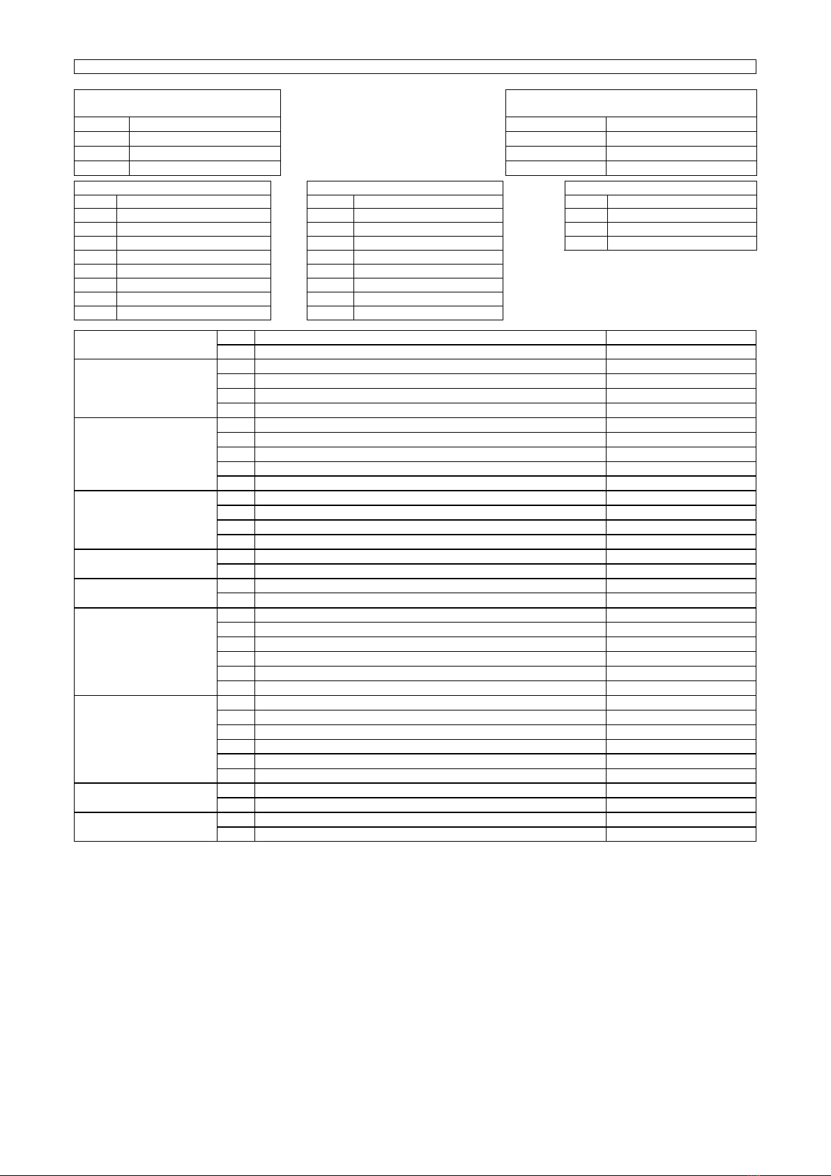
BUMPER INTERFACING (LOW VOLTAGE CONNECTION)
Generally there are 3 model o Bumpers:
• Si ple Toggle bu pers – this bumpers require a contact close when bumper Up or a pulse
or UP/Down the bumper
• Bu per Toggle + UP SWITCH – this bumper require a pulse or UP/Down the bumper and
2 or 1 switch or control the bumpers position.
• Bu per Toggle + UP/DOWN SWITCH – this kind o bumpers has 2 di erent motors and it
required the Steltronic H.V.B. or drive it.
Note: A.P.I. Bumpers output is always an N.O. Dry contact relays,
working mode is selectable by Front Desk so tware settings.
Simple toggle Bumpers connections
Auxiliary connection or toggle Bumpers + UP Switch connections
API A065 series Inter acing Via bowling (MC2)/Switch pinsetters
10
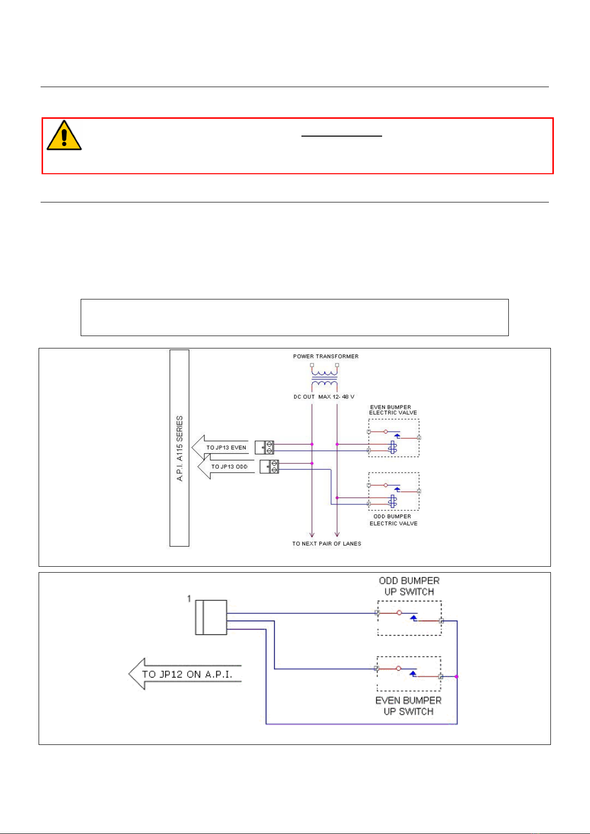
STELTRONIC HIGH VOLTAGE BOX [H.V.B]
The Bumpers with Toggle + UP/DOWN Switch need a High Voltage box to be drive by Scoring.
Steltronic developed an High voltage box (H.V.B.) ready to be used or bumpers, Glow light,
Maintenance call. Max current or external devices: 10 A. The HVB must be speci ically ordered or
the right AC input: 110/220/240 VAC. VDE plug or cable are not included and need to be ordered
separately.
Steltronic HVB
HVB connection for Bu pers with UP –DOWN Switch
Connect the UP and DOWN motor and the Up and down Switch.
HVB connection for driving White and glow pinsetter light
Short the Up switch (pin 6 and 5) .
Short the Down switch (pin 4 and 3).
Connect the AC power to the pinsetter using the pinsetter AC output or standard white light.
Connect the GLOW light to UP MOTOR output.
Connect the WHITE light to the DOWN MOTOR output.
HVB for driving Bar Call, echanic calls AC high voltage la ps
Short the Up switch (pin 6 and 5) .
Short the Down switch (pin 4 and 3).
Connect the AC power to the standard plug.
Connect the LAMP using the UP MOTOR output.
API A065 series Inter acing Via bowling (MC2)/Switch pinsetters
11
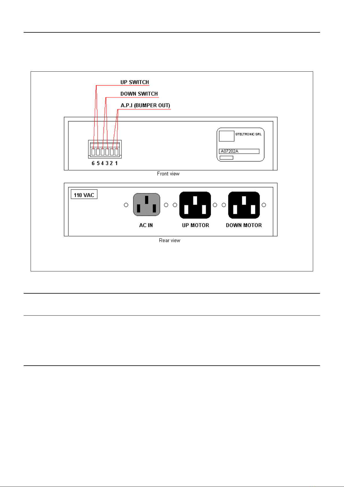
SAMPLE DIAGRAM FOR MECHANIC AND BAR CALL LIGHT CONNECTION
Example o High voltage connection
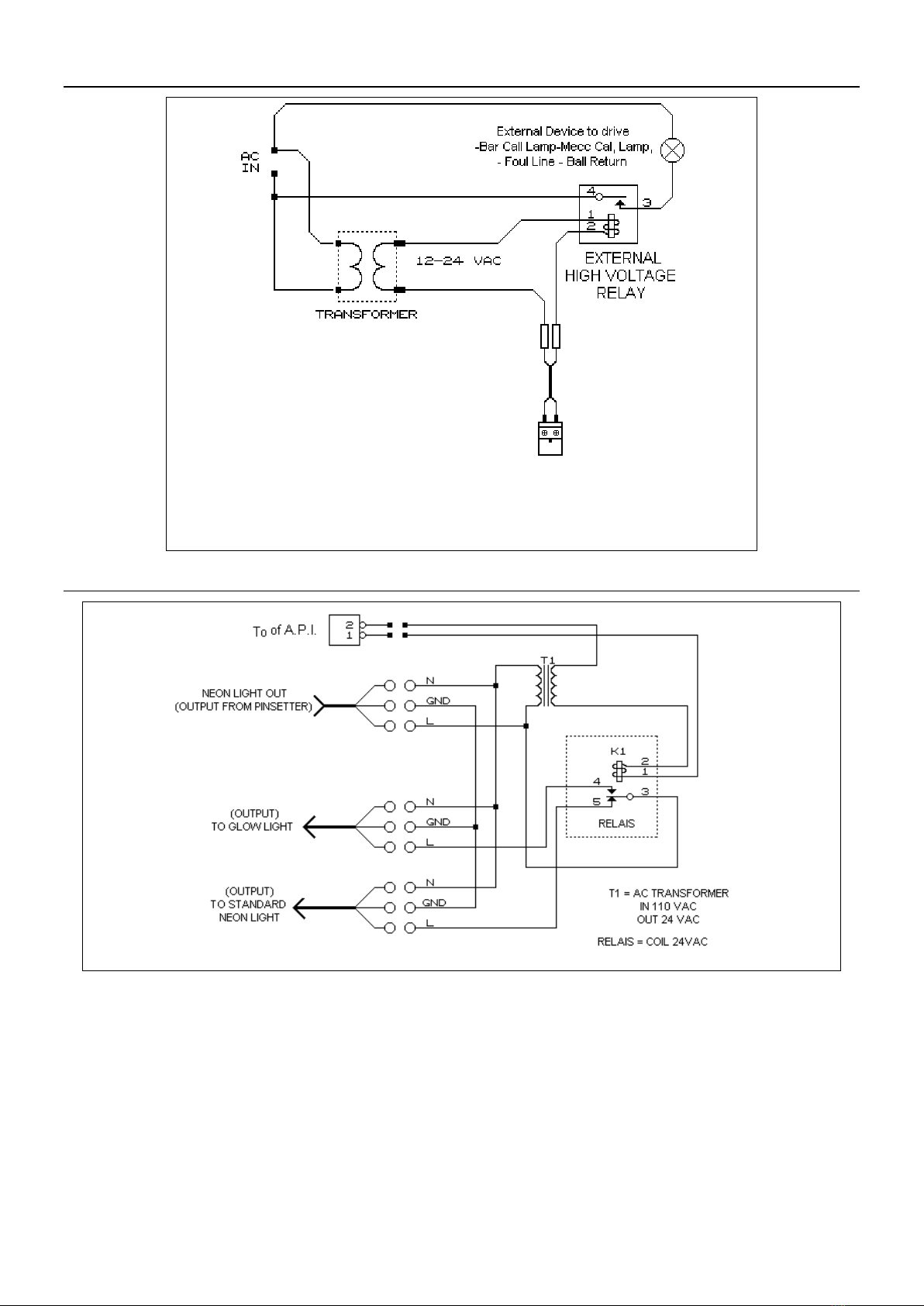
SAMPLE DIAGRAM FOR INSTANT GLOW CONNECTION

API A065 series Inter acing Via bowling (MC2)/Switch pinsetters
12
VIA Bowling (MC2) pinsetter Interfacing
A = A.P.I. A065 series
B = CAB-Y-CA0232A
Scoring signal cable (ODD pinsetter)
C = CAB-Y-CA0232B
Scoring signal cable (EVEN pinsetter)
D = VIA MC2 Scoring inter ace board
Via MC2 Scoring inter ace board
1 = Scoring interface connector
• Set the A.P.I. input jumpers or 24V input (2
nd
ball and oul).
• Open each pinsetter ront channel and look or MC2 Scoring inter ace board.
• Lay the cable CA0232A rom A.P.I. to ODD MC2 Scoring inter ace board.
• Lay the cable CA0232B rom A.P.I. to EVEN MC2 Scoring inter ace board.
• Place the Sciba like the standard installation.

API A065 series Inter acing Via bowling (MC2)/Switch pinsetters
13
Switch pinsetter chassis Interfacing
A = A.P.I. A065 series
B = CAB-Y-CA0232A
Scoring signal cable (ODD pinsetter)
C = CAB-Y-CA0232B
Scoring signal cable (EVEN pinsetter)
Switch pinsetter Chassis
(1 chassis control one lane pair)
Switch chassis rear view
• Set the A.P.I. input jumpers or 24V input (2
nd
ball and oul).
• Open each pinsetter ront channel and look or MC2 Scoring inter ace board.
• Lay the cable CA0232A* rom A.P.I. to the chassis, connecting the DB15 on ODD score input
connector.
• Lay the cable CA0232B* rom A.P.I. to the chassis, connecting the DB15 on EVEN score
input connector.
• Place the Sciba like the standard installation.
*NOTE: remove the oul input wires rom CA0232A and CA0232B cable i the chassis make
continues the oul cycle
Odd Score input
Even Score input

API A065 series Inter acing Via bowling (MC2)/Switch pinsetters
14
A.P.I. VIA Bowling\Switch pinsetter inter acing
API A065 series Inter acing Via bowling (MC2)/Switch pinsetters
15
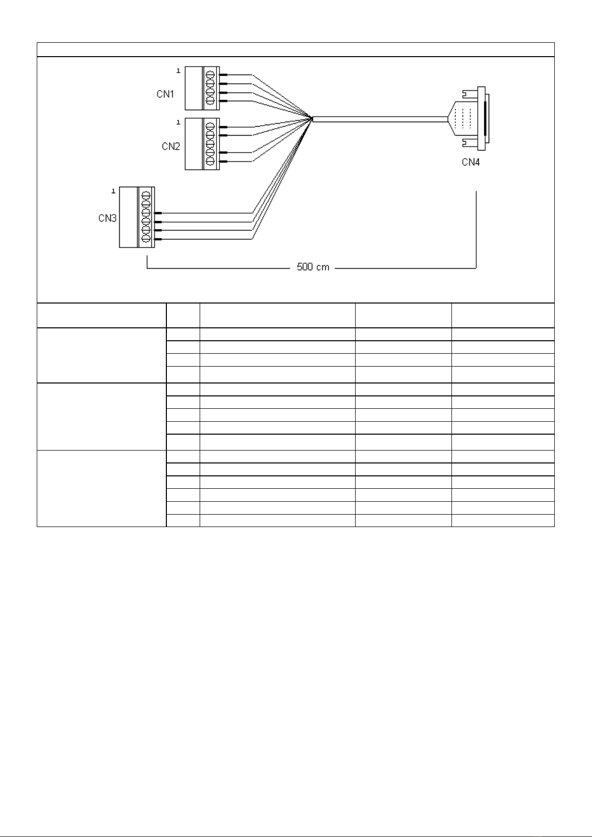
CAB-Y-CA0232A – CAB-Y-CA232B cables
Phoenix
Connector
PIN
SIGNAL
WIRE COLOUR 15 DB
ale connector
1 Foul input Yellow 6
2 Foul input Green 15
3 2
nd
ball input Brown 7
CN1
(Phoenix Combicon
Female
4pin p. 5.08
4 2
nd
ball input White 14
1 Pinsetter ON Output Grey 2
2 Pinsetter ON Output Pink 11
3 - -
4 Pinsetter CYCLE Output Blue 1
CN2
(Phoenix Combicon
Female
5 pin p. 5.08
5 Pinsetter CYCLE Output Red 10
1 - - -
2 - - -
3 Strike Output Black 3
4 Strike Output Purple 9
5 Gutter Output Grey/Pink 4
CN3
(Phoenix Combicon
Female
6 pin p. 5.08
6 Gutter Output Red/Blue 12
API A065 series Inter acing Via bowling (MC2)/Switch pinsetters
16
A.P.I. Software settings (Wins)
The ollowing operation must be per ormed rom WINS Front DESK, lane by lane or using the
multiple commands or A.P.I. LOGIN AS SERVICE BEFORE BEGIN.
MANDATORY
Via bowling MC2 pinsetter/switch chassis need at least FF version as A.P.I. so tware.
I the A.P.I. so tware is previous o FF version, proceed with A.P.I. Firmware upgrade.
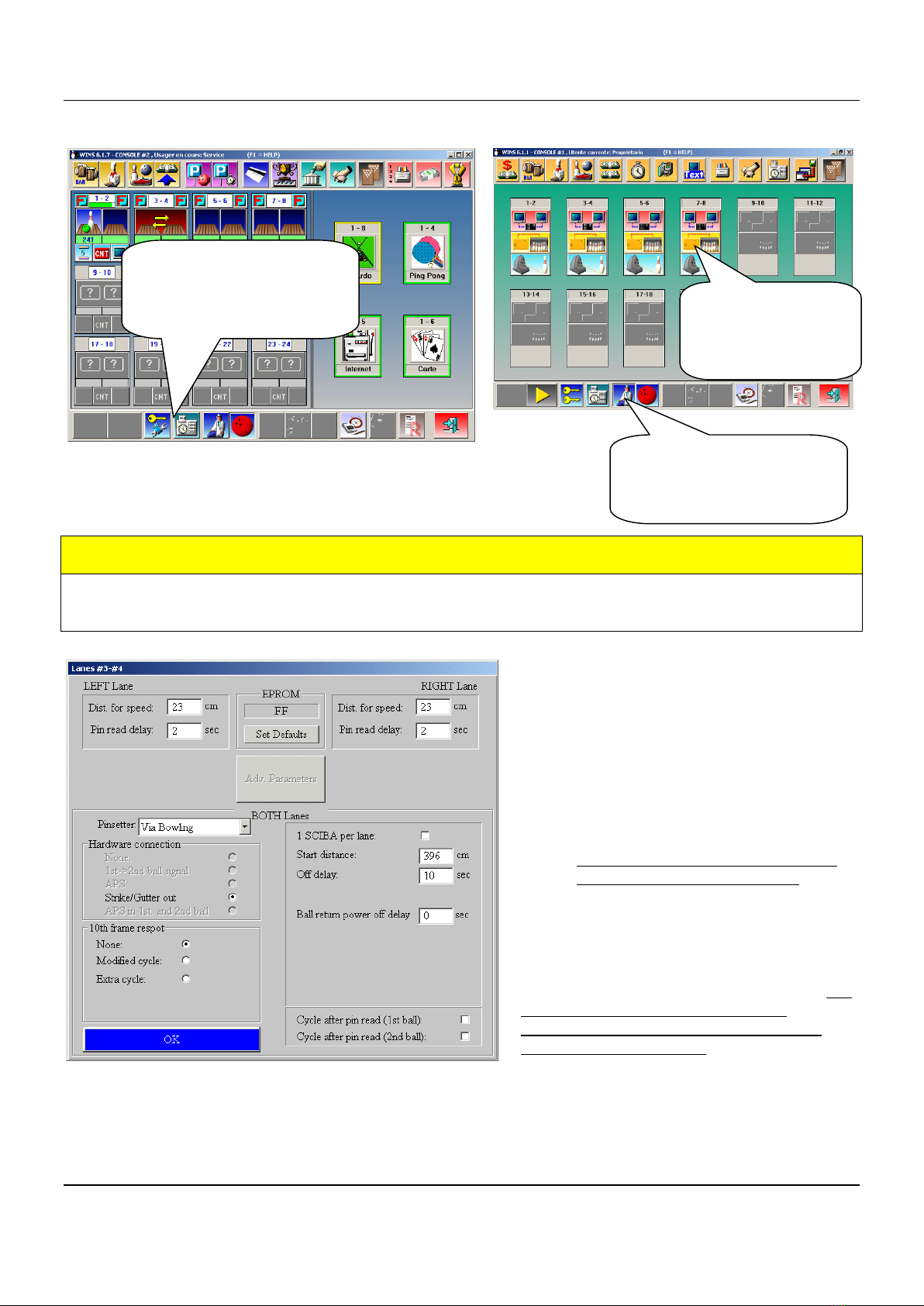
The irst MANDATORY operation is set the
Pinsetter model (VIA BOWLING) rom the
available list, than click on SET DEFAULT.
Note: choose VIA Bowling as pinsetter
setting even i is installed Switch pinsetter
chassis.
1. Select VIA BOWLING rom
Pinsetter list.
2. Click on SET DEFAULT button to
load the de ault parameters.
3. Veri y that Hardware connection is
Strike/Gutter out and 10
th
Frame
Respot is Modified cycle.
Adjust the Pin read delay i necessary, but
do not exceed 2.8 seconds or the
pinsetter will not execute correctly the
Strike and Gutter cycle.
The most standard parameters will be selected automatically, like the pins read delay, distance or
speed etc. Vary the parameter only when needed.
Following: list o the editable parameters
Open Wins Main Desk
program and identi y
yoursel as SERVICE
(password required)
Click on the DOCTOR
icon to access the SET
UP MENU SCREEN
Click on each
A.P.I. icon to
access the A.P.I.
menu.

API A065 series Inter acing Via bowling (MC2)/Switch pinsetters
17
DISTANCE FOR SPEED [LEFT - RIGHT LANE]
Clearance in centimeters between Speed and Start photocell. De ault value 23 CM.
PIN READ DELAY [LEFT-RIGHT LANE]
Delay or scan the pins a ter ball passes trough the start photocell. Time is in seconds; do not
exceed 2.8 seconds or the pinsetter will not execute correctly the Strike and Gutter cycle
Note: The PIN READ DELAY could be adjusted as need, it’s important scan the pins when they are
standing correctly on deck, be ore pinsetter table run.
START DISTANCE
Clearance, in centimeters, between Steltronic trigger sensor and last row o pins. The de ault value
is 396. Change this parameter (increasing the value) when the Sciba is installed with the extra
support or rise the Bumpers because photocells will see only a “cord” when the ball pass trough.
OFF DELAY
Timeout in second or switch o the pinsetter a ter the end o the game.
NOTAP+10FRAME RESPOT
For automatic 10
th
rame reset: the selection is MODIFIED CYCLE: pinsetter will receive a ake ast
strike pulse.
1 CAMERA PER LANE
Selection or ODD or Multiple Sciba. Tag the checkbox only i necessary. When a single camera or 2
camera or 2 lanes are installed, tag the checkbox 1 CAMERA PER LANE and set the selection
re erring to the next samples:
ODD LANE EVEN LANE
LEFT SCIBA = STANDARD
RIGHT SCIBA = STANDARD
ODD LANE EVEN LANE
LEFT SCIBA = CROSSED
RIGHT SCIBA = STANDARD
ODD LANE EVEN LANE
LEFT SCIBA = STANDARD
RIGHT SCIBA = CROSSED
ODD LANE EVEN LANE
LEFT SCIBA = CROSSED
RIGHT SCIBA = CROSSED
LEFT SCIBA = STANDARD
RIGHT SCIBA = NONE
LEFT SCIBA = CROSSED
RIGHT SCIBA = NONE

API A065 series Inter acing Via bowling (MC2)/Switch pinsetters
18
Wins Advanced A.P.I. settings for Bu pers
WARNING: Vary the suggested para eters only; do not edit the other fields
WAIT until the window dialogue is open, than
click on ADV Para eters button to load the
Advanced Parameters.
SETTINGS BUMPERS MODE
PARAMETER_15H = 0
[Bumper ON/OFF] – de ault -
Bumper out ALWAYS CLOSE until the next player begin
PARAMETER_15H = 1 to ..
[Bumper Toggle]
One pulse= Bump UP, next pulse = Bump Down
Value indicate length o close pulse (1 unit= 100 ms)
PARAMETER_15H = 1 to ..
[Bumper Toggle + UP SWITCH]
Value indicate length o close pulse (1 unit= 100 ms)
For UP switch detection mandatory set the 16H parameter
PARAMETER_16H = ..
Indicate the timeout or UP Switch detect.
Time starts a ter parameter 15H, i a UP/DOWN switch is not
detected be ore 16H time expires, score give another pulse or
bumper. Unit in 100 ms.
• At the end o modi ication, con irm with OK, save and exit.
Open Wins Main Desk
program and identi y
yoursel as SERVICE
(password required)
Click on the DOCTOR
icon to access the SET
UP MENU SCREEN
Click on each
A.P.I. icon to
access the A.P.I.
menu.

API A065 series Inter acing Via bowling (MC2)/Switch pinsetters
19
A.P.I. Software Update (WINS Scoring)
Contact Steltronic Customer Service (+39 030 2190830 or service@steltronic.com) requiring the last
API So tware update compatible with your pinsetter. The Steltronic customer service will send a
zipped ile contained the BIN ile or update.
Copy the ile onto Main Desk C drive and explode into a temporary directory
WARNING
Wins program must run be ore to proceed with next steps
Open the olders PROGRAMS / STELTRONIC and launch the API FIRMWARE UPGRADE application.
Select the destination lanes rom
LANE LIST window
Browse the olders to ind the
irmware ile (bin ile) (use the
button to browse the C drive), then
click on GO button.
A warning window will remind the ollowing
operations: lanes need to reboot be ore to begin
the update.
THE LANES REBOOTING IS AUTOMATICALLY.
At the next start, the lane computer will load the new ile and start the procedure to update the
A.P.I. On lane monitor, the procedure is displayed on blue screen.
The lane computer must trans ers 9 blocks on A.P.I., the operation require several minutes.
At the end o the loading, the lane monitors will display the message “ALL OK, IN 20 SECONDS
THE LANE WILL START” and the lane computer will restart by itsel . The update operations are
inished, now it’ s possible to use the score.

API A065 series Inter acing Via bowling (MC2)/Switch pinsetters
20
A.P.I. Software settings (FOCUS Scoring)
BASIC PINSETTER SETTINGS
PINSETTER CONTROL
As de ault suggest status choose AUTO; the pinsetter will switch and stay ON when the lane is in
use by bowlers; pinsetter will be turned and kept OFF a ter the Game/Time is over.
PINSETTER ON WHEN PRACTICE
Forces the pinsetter to normal on status when in practice
TEN PINS IN PRACTICE MODE
During practice mode, the score sends a ake strike pulse to the pinsetter that will replace a new set
o pins a ter every shot.
PINSETTER PHASE WITH SCORE
when enabled, the score checks the 2
nd
Ball signal be ore detecting the second shot o the rame.
KEEP ENABLE: disable this tag only i pinsetter is damage and can’t provide the 2
nd
ball in ormation
to the score.
(1) Start the
Focus program
and login as
authorized user
(2) Fast multiple
lane selection: click
on Action then on
Pinsetters
Click on
“Send to lane and
close” to save and
exit.


