Porter 330150 Instruction Manual

ASSEMBLY,INSTALLATION &USAGE MANUAL
B
ATTING
C
AGES
No. 330150 - 50' Long
No. 330170 - 70' Long
INST00333078
¤2017 PORTER ATHLETIC, INC. ALL RIGHTS RESERVED. 6-13-2017
Upon completion of the assembly/installation of this kit, make sure this
instruction sheet is in the possession of the owner or facility manager, to
save for future reference, and to order replacement parts.
No. 330150
BATTING CAGE - 50' Long No. 330170
BATTING CAGE - 70' Long

2
No. 330150 – Batting Cage – 50' Long
No. 330170 – Batting Cage – 70' Long
INSTALLATION INSTRUCTIONS
WARNING
xREAD ALL CAUTIONS AND WARNINGS THOROUGHLY BEFORE USING THIS EQUIPMENT.
xFAILURE TO COMPLY WITH THE FOLLOWING INSTRUCTIONS, CAUTIONS AND WARNINGS MAY RESULT IN
SERIOUS INJURIES AND/OR PROPERTY DAMAGE.
xTHE No. 330150 AND 330170 BATTING CAGES ARE DESIGNED TO PROVIDE LIMITED PROTECTION FOR
SPECTATORS. HOWEVER, STRICT SAFETY PRECAUTIONS AND ADULT SUPERVISION MUST BE OBSERVED
AT ALL TIMES TO MINIMIZE THE POSSIBILITY OF ACCIDENTAL INJURIES.
xSPECTATORS MUST BE INSTRUCTED TO STAND A SAFE DISTANCE FROM THE NETTING WHEN THE
BATTING CAGE IS IN USE, TO AVOID THE POSSIBILITY OF BODILY CONTACT WITH BALLS, BATS OR
OTHER EQUIPMENT.
xTHE OWNER OF THIS EQUIPMENT IS RESPONSIBLE TO ENSURE THAT ALL INDIVIDUALS FOLLOW THESE
SAFETY AND OPERATING INSTRUCTIONS TO AVOID INJURIES OR PROPERTY DAMAGE. PROPER USE AND
SUPERVISION OF THIS EQUIPMENT IS ESSENTIAL TO HELP REDUCE THE POSSIBILITY OF ACCIDENTS OR
INJURIES.
WARNING
READ ALL INSTRUCTIONS THOROUGHLY BEFORE ATTEMPTING TO ASSEMBLE THIS EQUIPMENT. ASSEMBLY
OF THIS EQUIPMENT MUST BE DONE BY PHYSICALLY CAPABLE ADULTS ONLY.
PARTS LIST
Item No. Part No. 330150 330170 Description
Quantity Quantity
1 UPRT 00326 100 8 10 Batting Cage Upright
2 PCAP 00061 002 8 10 End Cap
3 ROPE 00103 002 8 10 Hoist Rope Assembly
4 PULY 00015 0G0 8 10 Pulley
5 HDWE 58026 0E0 8 10 S-Hook
6 HDWE 07023 0E0 8 10 Eye-Bolt
7 HDWE 03013 0E0 8 10 5/16" Lock Nut
8 ROPE 00008 0G0 8 10 Rope Cleat
9 HDWE 06009 0E0 16 20 1/4" x 1-1/2" Lg. Flat Head Machine Screw
10 00330059 1 Batting Cage Net – 50' Long
10 00330079 1 Batting Cage Net – 70' Long
11 00418080 2 3 Net Tie-Down Stakes (Set of Eight)

3
8
1/4" tapped holes
for rope cleats
9
1
3
45
67
2
6
7
Detail "A"
1. Check all parts against Parts List on Page 2 to make sure all have been included.
2. Begin by assembling uprights. At top end, insert eye-bolt (6) into hole thru upright
(1). Secure with 5/16" locknut (7). Note - the eye must be in the horizontal position.
Tighten the locknut after rotating the eye-bolt. See Detail “A”.
3. Assemble pulley (4) and s-hook (5) to eye-bolt assembly (6) from Step No. 2.
Crimp both ends of s-hook completely closed, to prevent removal of pulley. See
Detail “A”.
4. Install end cap (2) onto top end of upright (1). See Detail “A”.
5. Each upright (1) has one set of tapped holes on one side of the upright. A rope cleat
(7) is assembled to each upright at these tapped holes, with 1/4" x 1-1/2" lg. flat head
machine screws (9). See Detail “A”.
If batting cage uprights are being used with outdoor ground sleeves or indoor floor
sleeves, follow the installation instructions provided with the sleeves. If batting
cage uprights are being installed permanently into concrete footings, proceed to
Step No. 6 below.
6. Locate and dig footings for each upright. CAUTION – Contact your local utility
companies to locate buried electrical, gas and water lines before digging holes for
footings. Also, check for overhead utilities. See Detail “B” for footing details, and
Detail “D” for footing locations.
TOP OF FOOTING AT POLE
MUST BE AT LEAST 12"
ABOVE PLAYING SURFACE
FOR PROPER DRAINAGE
CAUTION - CHECK
FOR LOCATIONS OF
BURIED POWER
CABLES, DRAIN
TILES, WATER LINES,
ETC. BEFORE
DIGGING HOLES FOR
FOOTINGS
SLOPE TOP OF
CONCRETE FOOTING
APPROXIMATELY 3"
BELOW GRADE FOR
PROPER DRAINAGE
FOOTING
DETAIL
1'-6"
DIA.
2'-6"
12"
3"
Detail "B"
2'-0"
The footer size is to be determined by the
architect/engineer and is based on local
codes and soil conditions.

4
Detail "C"
Knot plain end of hoist
rope assembly to rope
cleat for permanent
installation
11
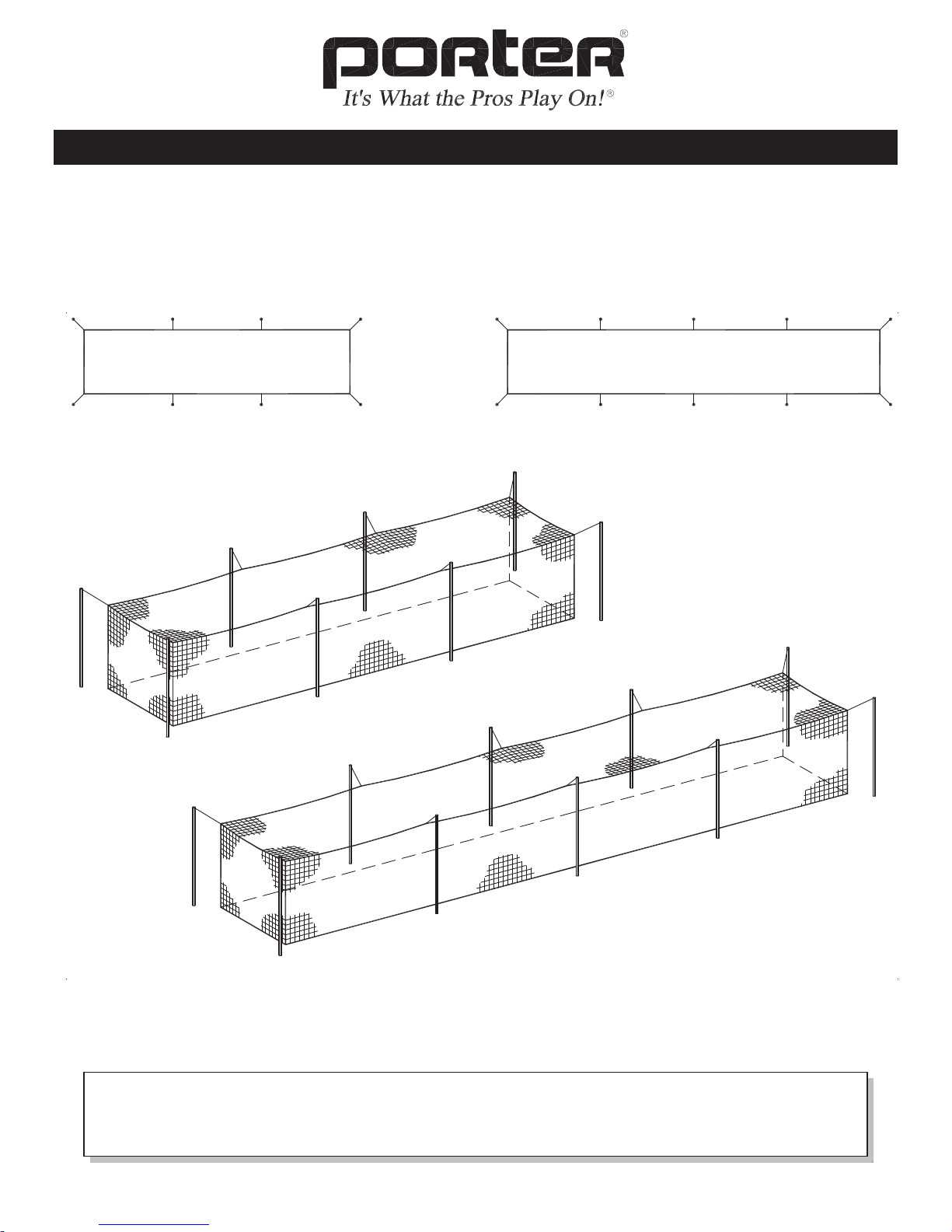
COMPLETED INSTALLATION
(SHOWN IN CONCRETE FOOTING)
3
2'-0" 11'-8"
7. Raise the assembled batting cage uprights into position in their holes, according to
the dimensions shown in Detail “D”. The four corner uprights are positioned at a
45qangle, with the rope cleats and pulleys pointed toward the batting cage. All
intermediate upright assemblies are rotated square with the cage, pointing toward
each other. Support each upright assembly at the proper location and height in the
hole, by clamping 2x4’s, etc. to the uprights. The bottom 2’-0" of each upright will
be below grade, with the top of the upright approximately 11'-8" above grade. See
Detail “C”.
8. Check once more the position, rotation and height of each upright, and check that the
upright is plumb. After doing so, pour the concrete footings.
9. Allow the concrete footings to cure for a minimum of three days before assembling
the hoist rope assemblies (3) to the uprights.
10. Feed the plain end of the hoist rope assembly (3) thru the pulley assembly on the
upright. See Detail “C”. The lower end of the hoist rope assembly should be
knotted to the rope cleat on the upright assembly, for a permanent installation.
Repeat for all batting cage upright assemblies.
11. Assembly of the batting cage uprights is now complete
12. Secure the batting cage net to the batting cage uprights. Prior to doing this step,
consult with the customer as to where the Velcro access opening should be located.
See Detail “D” for alternate locations for Velcro access opening.
13. Extend each hoist rope assembly (3) and attach to the batting cage net by hooking
the quick-links thru the grommets or loops on the net. Be sure to close each quick-
link. Pull down on each rope until the bottom of the net is just touching the ground,
and wrap the rope around the rope cleat until it is secure. See Detail “C”. Pull
evenly on all hoist rope assemblies, so that the net remains in the center of the cage.
14. Secure the bottom of the net to the ground, with the tie-down stakes supplied (11).
THIS WARNING IS GIVEN IN COMPLIANCE
WITH CALIFORNIA’S PROPOSITION 65:
WARNING
This product contains chemicals known to the
State of California to cause cancer, birth defects
or other reproductive harm.
WARNING: Cancer and Reproductive Harm –
For more information go to www.p65warnings.ca.gov
F

5
Porter Athletic, Inc.
601 Mercury Drive, Champaign, IL U.S.A., 61820
Toll Free: (888) 277-7778 xPhone: (217) 367-8438 xFax: (217) 239-2255
www.porterathletic.com
SAVE THESE INSTRUCTIONS FOR FUTURE USE
This manual suits for next models
1
Table of contents
Other Porter Accessories manuals
Popular Accessories manuals by other brands

Powerfix Profi
Powerfix Profi PMT 1.1 A1 translation of original operation manual

S+S Regeltechnik
S+S Regeltechnik HYGRASGARD AFF Series Operating Instructions, Mounting & Installation

Danfoss
Danfoss 176F3737 installation instructions

Siren Marine
Siren Marine SM-WLS3-BATT Guide

Emos
Emos P5734T Replacement

Audiovox
Audiovox 1070610 instruction manual