1
Copyright
©
2009
ILLUMRA.
All
rights
reserved.
Contact ILLUMRA: T: (801) 349-1200 | F: (801) 653-4257 | [email protected] | www.ILLUMRA.com AHD0193BInstallation
To mount the Self-powered Wireless Occupancy Sensor, choose one of the following mounting options below. For receiver installation
instructions, see appropriate installation guide.
OPTION A:
Ceiling Tile Mounting
Step 1: Read all mounting steps for this option before taking any action to mount the occupancy sensor.
Step 2: Remove ceiling tile from location in ceiling.
Step 3: Drill one 11/16” hole in ceiling tile. Position hole at least 3” from walls or other obstacles.
Step 4: Insert mounting bolt (B) through hole in ceiling tile.
Step 5: On hidden side of ceiling tile place large mounting washer (C) onto mounting bolt (B) and secure the washer by threading
mounting nut (C) onto mounting bolt.
Step 6: Return ceiling tile to proper location in ceiling.
Step 7: Place occupancy sensor (A) over visible portion of mounting bolt (B). Rotate occupancy sensor 90 degrees; the occupancy
sensor should snap rmly into position.
OPTION B:
Drywall Mounting
Step 1: Read all mounting steps for this option before taking any action to mount the occupancy sensor.
Step 2: Drill 2 5/16” holes in drywall or stud leaving 1 3/4” of space between the holes.
Step 3: If holes were drilled in drywall, insert plastic wall anchors (not included) into holes. If holes were drilled in stud, anchors
are not required.
Step 4: Insert suitable screws into anchors or holes in stud. Leave about 1/8” of screw protruding from ceiling (in addition to head
of screw).
Step 5: Place occupancy sensor (A), solar cells face down, over screw heads protruding from ceiling. Screw heads will insert into
cutouts in top of occupancy sensor. Slide occupancy sensor about 1/2”; the sensor should snap into place.
Programming
Step 1: Read all programming steps before associating this transmitter with a receiver.
Step 2: Use this transmitter with a compatible receiver. See list: “Compatible ILLUMRA Devices”.
Step 3: Follow programming instructions found in the installation guide for the appropriate ILLUMRA receiver.
Step 4: At the point in the receiver programming instructions where a radio signal must be transmitted from the occupancy sensor
to the receiver, use the tip of a pencil to press the “LEARN” button on the occupancy sensor. (Found under front plastic
tab; use slotted screwdriver to pry tab open. See image below.)
Step 5: Upon completing the receiver programming instructions, replace front plastic tab on occupancy sensor. (Insert non-slotted
end rst. Next, snap in slotted end.)
Installation Guide
E3T-M04-SB24 (450 sq. ft.)
E3T-M15-SB24 (1500 sq. ft.)
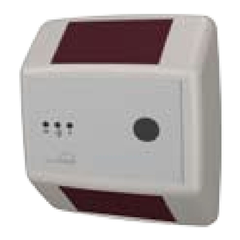
Self-powered Wireless
Occupancy Sensor
Overview
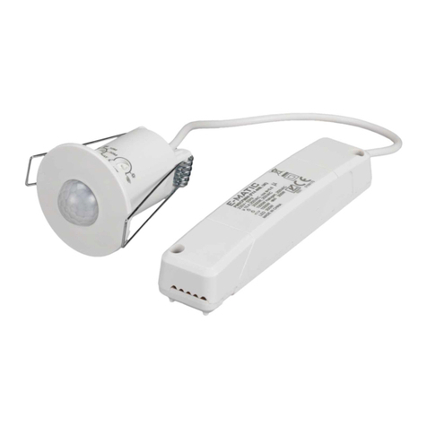
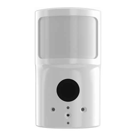
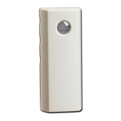
The ILLUMRA Self-powered Wireless Occupancy Sensor provides fast and simple installation of automatic OFF controls. Such
controls ensure lights and devices are turned off in unoccupied areas of a building, decreasing electricity consumption. The occupancy
sensor is intended to be mounted on ceiling tiles, but may also be mounted on drywall ceilings. This device is powered by ambient light
available in a room and may optionally be powered using 3 AAA batteries.
Compatible Devices
E3R-R12-3HOBP; 120V 3-wire Relay Receiver
E3R-R24-3HOBP; 240V 3-wire Relay Receiver
E3R-R27-3HOBP; 277V 3-wire Relay Receiver
E3R-R12-5IBBP; 120V 5-wire Relay Receiver
E3R-R24-5IBBP; 240V 5-wire Relay Receiver
E3R-R27-5IBBP; 277V 5-wire Relay Receiver
E3X-R12-5IBBP; 120V 5-wire Relay Receiver + Repeater
E3X-R24-5IBBP; 240V 5-wire Relay Receiver + Repeater
E3X-R27-5IBBP; 277V 5-wire Relay Receiver + Repeater
E3R-D12GP; Plug-in Dimmer/Relay Receiver
E3X-MRCFP-04; Room Controller (0 input, 4 outputs)
E3X-MRCFP-13; Room Controller (1 input, 3 outputs)
E3X-MRCFP-22; Room Controller (2 inputs, 2 outputs)
E3X-D01FP; 0-10V LED Dimmer
E3X-D02FP; 24VDC LED Dimmer
Components Included
The following items are included with this product:
A -- (1) ILLUMRA Self-powered Wireless Occupancy Sensor
B -- (1) mounting bolt
C -- (1) large mounting washer
D -- (1) mounting nut
Tools Needed for Installation
Phillips screwdriver
Drill
11/16” drill bit
Pencil
Ruler
5/16” drill bit (for drywall mounting)
(2) Plastic wall anchors (for drywall mounting)
(2) Suitable screws (for drywall mounting)
■
■
■
■
■
■
■
■
■
■
■
■
■
■
■
■
■
■
■
■
■
■
■
■
■
■
■
