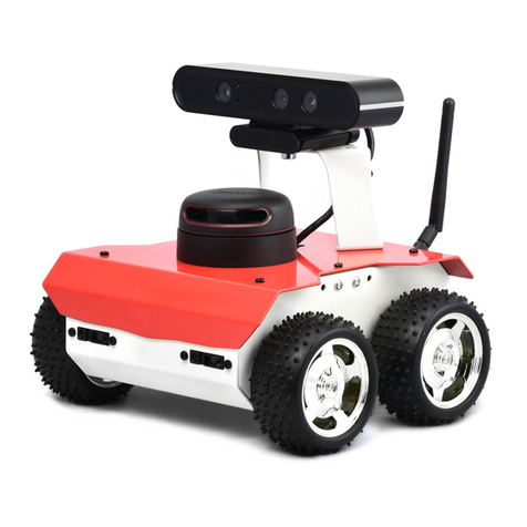
Stensat Sten-Bot Robot Kit User manual

Sten-Bot Robot Kit
Stensat Group LLC, Copyright 2013

Legal Stuff
●Stensat Group LLC assumes no responsibility an /or liability for the
use of the kit an ocumentation.
●There is a 90 ay warranty for the Sten-Bot kit against component
efects. Damage cause by the user or owner is not covere .
●Warranty oes not cover such things as over tightening nuts on
stan offs to the point of breaking off the stan off threa s, breaking wires
off the motors, causing shorts to amage components, powering the
motor river backwar s, plugging the power input into an AC outlet,
applying more than 12 volts to the power input, ropping the kit, kicking
the kit, throwing the kit in fits of rage, unforseen amage cause by the
user/owner or any other metho of estruction.
●If you o cause amage, we can sell you replacement parts or you
can get most replacement parts from online har ware istributors.
●If you nee to contact us, go to www.stensat.org an click on contact
us.

3
Program Overview
●Assemble Kit
●Motor assembly
●Base plate assembly
●Electronics plate assembly
●Programming
●Calibration
●Running the Maze

4
Parts List
●4 – 3/16” 4-40 screws
●8 – 1/4” 4-40 screws
●8 – 1/2” 4-40 screws
●4 – 1” 4-40 screws
●24 – 4-30 Kep nuts
●2 – 1/4” stan offs
●4 – 1.5” stan offs
●4 – right angle brackets
●1 – metal base plate
●2 – motor plates
●2 – geare motors
●2 – wheels
●1 – castor
●1 – battery hol er
●1 – processor boar
●1 – sol erless brea boar
●10 – jumpers
●1 – ultrasonic range sensor
●1 – LED
●1 – 270 ohm resistor
●1 – Photoresistor
●1 – 4.7K ohm resistor
●1 – micro-switch plus har ware
●1 – USB cable
●1 – CD

5
Tools Nee e
●Philips screw river
●1/4 inch nut river
●Jeweler bla e screw river

6
How the Robot Works
●4 AA Batteries power the robot.
●The processor boar executes a
program to control the motors an
operate the ultrasonic sensor.
●The motor controller supports two
motors.
●Two control signals are use to
control the irection an operation
of each motor.
●A control signal causes the ultrasonic
range sensor to sen out a 'ping'. A
signal goes back to the processor when
the echo is etecte . The processor
times how long it takes to receive the
echo to figure out istance.
Battery
Battery
Processor
Boar
Processor
Boar
Motor
Controller
Motor
Controller
Left
Motor
Left
Motor
Right
Motor
Right
Motor
Ultra-
Sonic
Ranger
Ultra-
Sonic
Ranger

7
Motor Assembly
●The two wheels nee to be mounte to
the base plate. A motor mount a apter
nee s to be assemble .
●Notice that one si e of the motor has a
circular plastic shape sticking out. Insert
¼ inch screw as shown an secure the
¼ inch stan off. Tighten with the screw.
Make sure the orientation is as in the
picture. The stan off threa s nee to
point away from the motor.
1/4 inch

8
Motor Assembly
●Align the motor mount a apter plate to the si e of the motor. Secure the
back en with 1 inch long screws
●Secure the top screw with a nut. For the bottom screw, install a right angle
bracket. Use the larger hole that is not threa e . Secure with a nut.
●Secure the stan off with a nut.
●Install a secon bracket with a ¼ inch screw an nut. Use the hole that is not
threa e .
1 inch screws
1/4 inch screw

9
Motor Assembly
●Assemble the secon motor in the mirror image of the first.
●The two motors shoul look like below.
¼” 4-40 ¼” 4-40
1” x 2
1” x 2
¼“ stan offs

10
Mounting the Motors
●Align the brackets to the holes shown in
the picture.
●Secure with two 3/16 inch screws from
the bottom si e.
●You may nee to loosen the screws on
the motor mount brackets to align the
brackets.
●Re-tighten all screws.
3/16”

11
Robot Plate Assembly
●With the motors installe , mount the caster at the rear using the two holes
an the screws from the caster parts.
●Secure the caster hol er with the two screws an nuts.

12
Electronics Base Plate
●Base plate is for mounting
sol erless brea boar an
processor boar
●Sol erless brea boar is to be
mounte in the marke rectangular
area .
●Use the 1/2 inch screws an
nuts to secure as shown in the
next page.
●Insert the screws from the top
through the sol erless brea
boar an secure with nuts on
the back si e.
●Make sure the sol erless brea
boar is oriente as shown in
the picture on the next page.
Sol erless
Brea Boar
Holes

13
Processor Boar Mount
●The process boar is mounte
ifferently.
●Insert screws from the back si e
an install a nut on each screw. The
nuts will serve as stan offs for the
processor boar .

14
Electronics Base Plate Assembly
●Place the processor boar
on top of the nuts.
●Insert another set of four
nuts to secure the processor
boar .

15
Mounting Electronics Plate
●Install four 1.5 inch long stan offs with the threa e en inserte into the
plate.
●Secure with nuts from the bottom si e of the plate.
1.5 inch
Stan offs
1.5 inch
Stan offs

16
Mounting the Electronics Plate
●Secure the electronics plate on top of the stan offs using 4-40 1/4 inch
screws.
¼ inch
Screws
¼ inch
Screws

17
Installing the Battery Hol er
●To install the battery hol er, take two pieces of ouble si e tape an stick
them to the un ersi e of the battery hol er.
●Peel the other si e an stick it to the base plate as shown.
●Using a small bla e screw river, secure the battery hol er wires to the
processor boar .
Re wire to + Si e
Closest to switch Black wire to
right of Re

18
Installing the Wheels
●The wheels are installe by pressing them onto the geare
motor shaft. The shaft is keye . Press fit the wheel onto the
shaft.

19
Processor Specifications
●Compatible to 8MHz ATMEGA168 ar uino boar s
●8MHz operating spee
●16KB Program memory
●1KB Ram
●512 Byte EEPROM
●6 Digital IO ports
●Can be configure as input, output, Servo, PWM
●6 Analog ports
●0-5 volt range
●I2C Interface
●Built in pull up resistors
●Supports 100 KHz an 400 KHz spee s
●UART Interface
●Up to 57600 bau
●Share with USB port
●USB an External power up to 12 V
●500 ma max current

20
Processor Boar Pinout
●Digital Pins
●D3, D5, D6, D9, D10, D11
●Can be configure as
●INPUT
●OUTPUT
●Servo
●PWM
●Each igital pin has 5V an GND in a
row.
●Allows servos to be connecte
irectly
●500ma total for all igital ports
●Digital 5V requires external power
source
●Separate from USB power to
protect PC
●Analog Pins
●0,1,2,3,6,7 available
●5V always available
●0 to 5 volt input range
●Higher voltages will cause amage
Digital Pins
Analog Pins
Table of contents
Other Stensat Robotics manuals
