Steril-Aire SE Series Manual

CAUTION 1: TURN ALL POWER OFF. NEVER EXPOSE EYES OR SKIN TO UVC LIGHT FROM ANY SOURCE - WEAR GLOVES,
FACE SHIELD AND COVER ALL EXPOSED SKIN. DO NOT TOUCH EMITTERTMGLASS WITHOUT GLOVES.
CAUTION 2: INSTALL EMITTER TUBE BEFORE APPLYING POWER. FAILURE TO DO SO WILL TRIGGER THE "END-OF-LAMP-
LIFE CIRCUIT" AND THE EMITTER WILL FAIL TO LIGHT! IF THIS HAPPENS SHUT OFF POWER FOR 10 SECONDS, REINSTALL /
INSTALL EMITTER AND TURN POWER BACK ON. EMITTER WILL LIGHT.
NOTE: Read this entire instruction sheet before starting the installation. Made in USA
pWARNING
!
Before installing fixture or performing maintenance or service on
fixture, turn off main power switch to unit. Electrical shock can cause
injury or death. There may be more than one disconnect switch.
pCAUTION
!
Never expose eyes or skin to ultraviolet light from any source. After
installation, provide an interlock to turn offgermicidal lamps when
access door is opened. Lamp must be off before entering HVAC unit
to perform maintenance or service. Personal injury may result.
pCAUTION
!
Do not touch lamp glass without gloves. Damage to Emitter™ may
result. Oil from fingerprints will permanently etch glass of lamp and
weaken structure. Clean lamp after handling.
pCAUTION
!
Use only specified high-output, low temperature lamp with this
fixture. Use of a lower wattage or incorrect lamp can result in
damage to accessory or Emitter.
Safety Considerations. . . . . . . . . . . . . . . . . . . . . . . . . . . . . . . . . . . . . . . . . . . . . . . 1.0
General . . . . . . . . . . . . . . . . . . . . . . . . . . . . . . . . . . . . . . . . . . . . . . . . . . . . . . . . . . 2.0
Installation. . . . . . . . . . . . . . . . . . . . . . . . . . . . . . . . . . . . . . . . . . . . . . . . . . . . . . . . 3.0
Operation & Maintenance . . . . . . . . . . . . . . . . . . . . . . . . . . . . . . . . . . . . . . . . . . . . 4.0
Trouble Shooting . . . . . . . . . . . . . . . . . . . . . . . . . . . . . . . . . . . . . . . . . . . . . . . . . . . 5.0
Illustrations . . . . . . . . . . . . . . . . . . . . . . . . . . . . . . . . . . . . . . . . . . . . . . . . . . . . . . . 6.0
Spare or Replacement Parts . . . . . . . . . . . . . . . . . . . . . . . . . . . . . . . . . . . . . . . . . 7.0
1.0 SAFETY CONSIDERATIONS
TABLE OF CONTENTS
MODEL
SE SERIES
120-277 Vac.
Patents 5,334,347; 5,817,276; 5,866,076; 6,245,293; 6,267,924;
6,280,686; 6,313,470; 6,372,186; 6,423,882; 6,500,267; 6,589,476; 6,627,000
INSTALLATION, OPERATION AND MAINTENANCE INSTRUCTIONS
Improper installation, adjustment, alteration, service,
maintenance, or use can cause fire, electrical shock, or
other conditions which may cause personal injury or
property damage. Consult a qualified installer, service
agency, or your supplier for information or assistance.
The qualified installer or agency must use factory kits or
accessories when installing this product. Refer to the
individual instructions packaged with kits or accessories
when installing them.
Follow all safety codes, wear safety glasses and work
gloves. Read all instructions thoroughly and follow any
warnings or cautions attached to any accessed area.
Consult local building codes and the National Electrical
Code (NEC) for special requirements.
Understand the signal words DANGER, WARNING or
CAUTION. These words are universally used for overall
safety. DANGER identifies the most serious hazards,
which will result in severe personal injury or death.
WARNING signifies hazards, which could result in
personal injury or death. CAUTION is used to identify
unsafepractices, which would result in minor personal
injury or product and property damage.
pCAUTION
!
Lamp contains a small quantity of mercury.If an lamp breaks, clean
and dispose of with care.

2.0 GENERAL
3.0 INSTALLATION
4.0 OPERATION & MAINTENANCE
pCAUTION
!
Other voltages will void the warranty and do permanent damage to
the entire unit. Fixtures should be operated continuously to preclude
the development of mold and bacteria.
2
pCAUTION
!
Install Emitter tube before applying power. Failure to do so will
trigger the "end-of-lamp-life circuit" and the Emitter will fail to light!
If this happens, shut off power for 10 seconds, reinstall/install
Emitter and reapply power. Emitter will light.
2.1 Emitters™ (lamps) may be installed anywhere to
bathe an air stream or surfaces with germicidal UVC
enegy. It is best that they be located at known growth
areas such as downstream of the cooling coil and over the
drain pan or where best accommodates the system. They
may also be placed in a return air duct, supply duct, mixed
air plenum, point of delivery or any combination thereof to
suit the application.
2.2 When choosing the site, make sure that it can be
supplied with the necessary power requirements, and
suitable physical access for service.
2.3 Reflecting UVC energy is recommended as it
enhances irradiance. Lining the UVC cavity with aluminum
allows photons to bounce reducing possible shadow areas
thus increasing efficacy.
2.4 Permanently installed radiometers are the
recommended choice for monitoring the relative output of
asensitive or large system for lamp changeout. In general,
UVC installations are sized to allow for an approximate
50% drop in total UVC output for mold control. Consult
factory specifications for infectious disease control.
3.1 Consult all applicable codes before installing.
Checkfixture label(s) for the correct power requirements
and supply the correct voltage from a suitable, protected
(fused), and grounded power source.
3.2 The lamp access door or panel should be
interlocked with the power source to turn lamp(s) off when
the system is opened. It should have signs (provided) in
appropriate languages alerting maintenance personnel to
the possible hazard of looking at or exposing skin to UVC
energy. Service accesses may be equipped with a glass or
Lexan®window to view Emitters. UVC energy does not
penetrate common glass or Lexan®.
3.3 UVC energy may damage some plastics except
for UV rated and HVAC style drain pans. Wrap suspect
items with aluminum tape; use metallic conduit or use
other appropriate shielding where these items may be in
"line of sight" of UVC.
3.4 Determine the most desirable location for the
intended use and install reflecting material. CAUTION: Do
not drill into coil, Freon lines or other mechanical
equipment.
3.5 Using the fixture base as a template, scribe and
then create one insertion hole, 1" diameter on the
mounting surface for the Emitter. Drill suitable holes for
each fastener (unless using self-taping screws). Using the
proper #10 fastener for your application, install fixture(s)
and wire in accordance with the applicable code.
3.6 Locate Emitter without touching glass with bare
hands and clean using a Steril-Aire Cleaning kit. Make
sure the "O" ring is toward and pushed onto the white
ceramic base of the Emitter. Release the holding spring on
the fixture base, lift it up and install the Emitter by grasping
the white base. Carefully push the lamp through the fixture
into the plenum until seated. Hold in and lock in place by
affixing the spring wire fastener to its lances. Push on the
power plug while noting the rectangle orientation of the
pins. Do not force. If the plug does not easily engage the
pins,rotate it 90 degrees.
3.7 Test all circuits and turn system on. A "blue hue"
will glow from each Emitter indicating that each fixture is
working. Caution: View onlywith all skin
covered and use a full face mask.
3.8 Affix the included "WARNING LABEL" in plain
sight to the A/C unit. Protect labels against poor
conditions if necessary and replace when worn.
3.9 Emitters must be changed annually or sooner to
maintain design output. The interval depends on the
application, on/off switches per dayand/or hours used. A
Steril-Aire UV Radiometer Kit can monitor UVC output to
determine lamp change-out.
3.91 Affix the included label for changing the emitter to
the outside of the housing.
4.1 Emitters should operate all the time. It is not
recommended to cycle the Emitters by time clock or fan
operation.
4.2 Emitters need periodic replacement to maintain
design output. The changeout basis depends on the
application, number of times switched per day and/or
hours of operation. Replace Emitter tubes when output
falls to 50% of initial output (or as specified) by actual
radiometer measurements.
4.3 If a radiometer is not available,Emitter(s) should
be replaced after 9,000 hours or in accordance with an
infectious disease application specification.
5.0 TROUBLESHOOTING
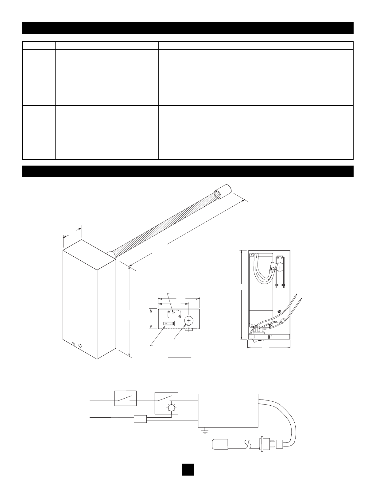
6.0 ILLUSTRATIONS
3
ITEM
5.1
SYMPTOM
Emitter™ Does Not Light
RECOMMENDED ACTION (in order of priority)
1. Ensure that fixture cover is affixed to base and that it trips the interlock switch.
2. Ensure that on/off switch is set to on.
3. Turn off power for 10 seconds, and then turn power back on.
4. Replace Emitter with known working Emitter. Normal replacements recommended
once per year.
5. Check line voltage.
6. Check wiring to Emitter.
7. Replace power supply.
5.2 Low Output (Radiometer Reading)
or Visibly Weak Light
1. Replace Emitter with known working Emitter.
2. Check line voltage.
3. Check wiring to Emitter.
5.3 Red/Orange Light 1. Check ambient temperature. If the temperature is at or below 35°F, Emitter is too
cold to operate properly.
2. If ambient temperature is in excess of 35°F, follow actions for the
Low Output symptom.
2"
9.00
9"
16", 20", 24", 30", 36", 42"
1/2" CONDUIT INLET
4.3
END VIEW
OFF/ON SWITCH
BLACK
WHITE
INTERLOCK SWITCH
3.1
2.0
4.3
BLACK
WHITE
INTERLOCK
SWITCH
LIGHTED ON/OFF
SWITCH ELECTRONIC BALLAST
BLUE END
120 THRU 277 V
50 / 60 HZ
EMITTER
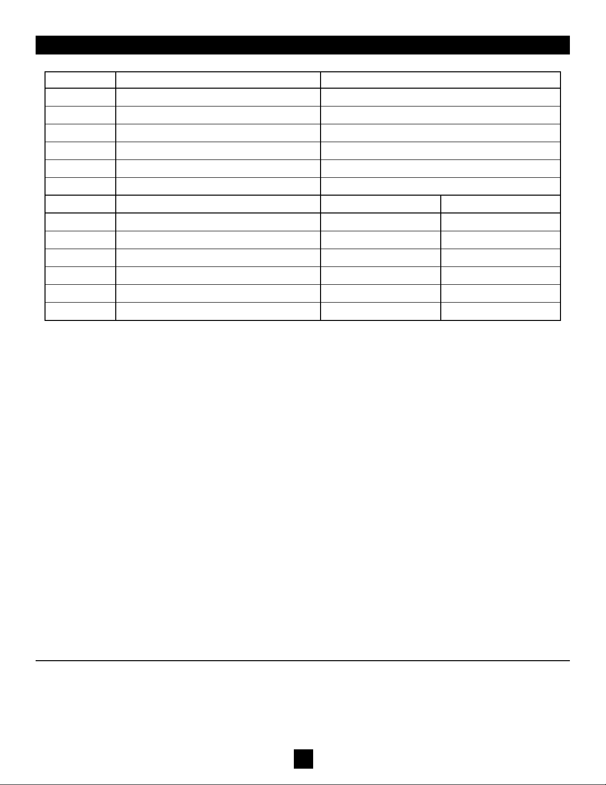
7.0 SPARE OR REPLACEMENT PARTS
ITEM
7.1
7.2
7.3
7.4
7.5
7.6
7.7
7.8
7.9
7.10
7.11
DESCRIPTION
POWER SUPPLY 120-277 V
COVER SE
SPRING
SWITCH, ON/OFF
SWITCH, INTERLOCK
EMITTER
GTS 16 VO
GTS 20 VO
GTS 24 VO
GTS 30 VO
GTS 36 VO
GTS 42 VO
PART NUMBER
10000155
11000102
11000104
11000112
11000103
LENGTH
16”
20”
24”
30”
36”
42”
PART NUMBER
21000100
21000200
21000300
21000400
21000500
21000600
Thank you for choosing the #1 "UVC for HVAC" product sold worldwide. Please contact your local supplier or Steril-Aire
directly if we can provide any further information or service. Your satisfaction is very important to us.
Please call 1-800-2-STERIL (783745) or log onto www.steril-aire.com.
Steril-Aire, Inc. cannot and does not guarantee that all organisms will be inactivated or killed or that use of Steril-Aire, Inc.
UVC Emitters will prevent infection or illness. Additionally, the health aspects associated with the use of this product and
its ability to aid in disinfection of environment air havenot been investigated byUL.
44#1318
Other Steril-Aire Laboratory Equipment manuals


