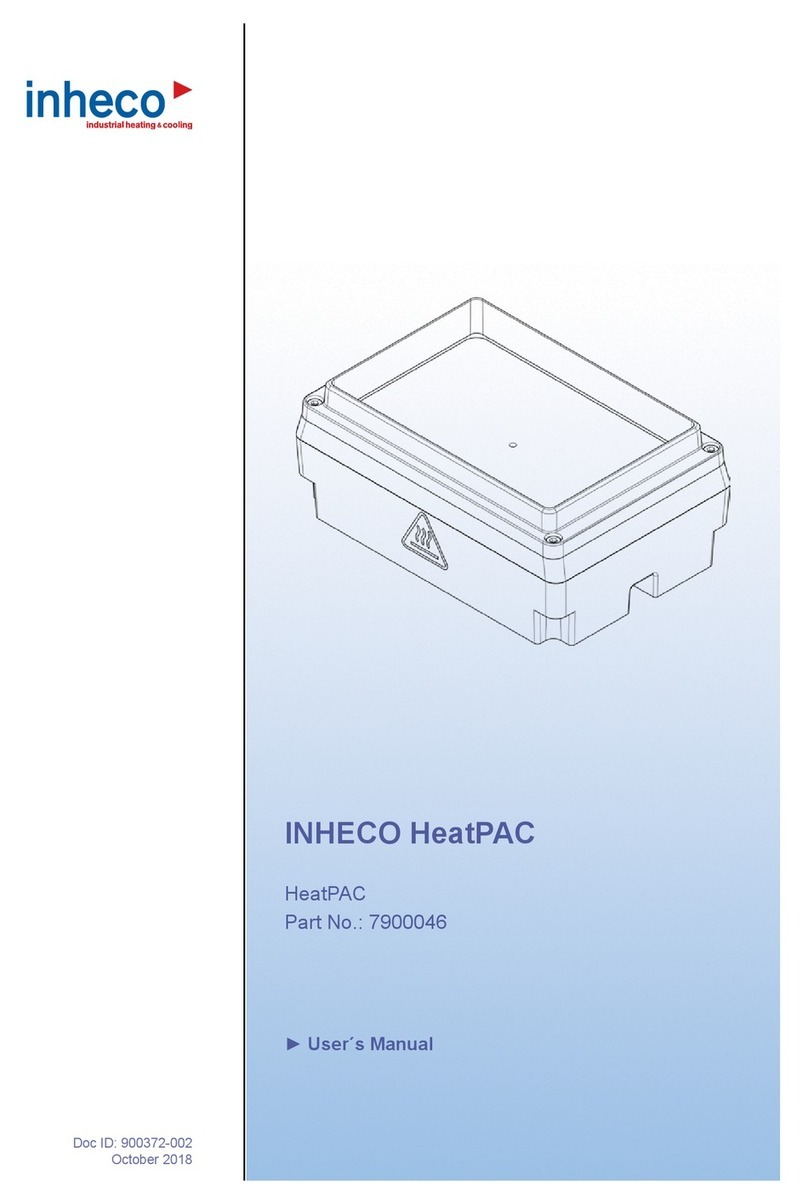
INHECO ODTC Verification Tool 96 User manual

Doc ID: 900905-000
October 2018
ODTC®Verification Tool
(OVT)
Set Part No.: 790200X
Insert gap closure in ODTC (at position of removable Block)
Insert gap closure in ODTC (at position of removable Block)

INHECO
Doc ID: 900905-000
October 2018
2
reserves the right to modify their
products for quality improvement. Please note that such modifications may not be
documented in this manual.
This manual and the information herein have been assembled with due diligence.
does not assume liability for any misprints or cases of damage resulting
from misprints in this manual. If there are any uncertainties, please feel free to contact
[email protected]. → How to contact INHECO, page 6.
The brand and product names within this manual are registered trademarks and belong
to the respective titleholders.
0

INHECO
Doc ID: 900905-000
October 2018
03
......................................................................................... 04
General Information ..................................................................................... 04
Explanation of Symbols ............................................................................... 05
Abbreviations and Glossary ........................................................................ 05
Warranty ...................................................................................................... 06
How to contact INHECO .............................................................................. 06
.................................................................................. 07
Intended Use ............................................................................................... 07
Components - scope of supply .................................................................... 07
Functional Elements .................................................................................... 08
Labels .......................................................................................................... 11
Technical Data............................................................................................. 12
.................................................................................... 13
Product-specic Risks ................................................................................. 13
Technical Alterations ................................................................................... 14
Malfunctions................................................................................................. 14
.................................................................. 15
Installation OVT control software................................................................. 15
Installation of Data Logger driver................................................................. 15
Network conguration .................................................................................. 16
Energy saving settings of connected PC......................................................16
............................................................ 17
Scope of Supply........................................................................................... 17
Initial Operation............................................................................................ 17
Start Verication .......................................................................................... 17
............................................................................................... 24
Software Updates ........................................................................................ 24
Support ........................................................................................................ 24
Return for Repair only with RMA Number ................................................... 24
Transportation and Storage ......................................................................... 24
Cleaning....................................................................................................... 24
Decontamination.......................................................................................... 25
Thermal Verication..................................................................................... 25
Shut Down and Disposal ............................................................................. 25
........................................................................................ 26
OVT is not connecting to ODTC®................................................................. 26
................................................................................................ 27
Miscellaneous .............................................................................................. 27
.................................................................................................... 28
CE Declaration ............................................................................................ 28
................................................................................................. 29
Certicate of temperature verication .......................................................... 29
................................................................................................. 31
Certicate of Calibration ............................................................................. 31

INHECO
Doc ID: 900905-000
October 2018
04
1
1.1.
Read the user instructions completely. The manual explains how to handle the ODTC®
Verification Tool (abbreviated: OVT ) with Part#: 790200x.
Part# 7902000-set consists of:
Data Logger connected with the OVT Measurement Head 96 well and Software
Part# 7902001-set consists of:
Data Logger connected with the OVT Measurement Head 384 well and Software
In the following OVT is used for the complete set.
In case the instructions contained in this manual are not followed, injury or product
damage cannot be excluded.
Missing or insufficient knowledge of the manual leads to loss of liability against
INHECO GmbH.
This manual is part of the OVT and must be retained until the device is disposed of and
must be passed on with the OVT when the device is taken over by a new user.
Manual instructions must be followed in order to limit the safety risk during operation of
the OVT.
Security-related warnings in this manual are classified into 4 hazard levels:
- The signal word WARNING indicates hazards which – without precautionary
measures – can result in death or serious injuries.
- The signal word CAUTION indicates hazards which – without precautionary
measures – can result in minor to moderate injuries.
- The signal word NOTE stands for the general precautionary measures that have to
be taken to avoid damaging the device.
- The signal word NOTICE stands for the general measures that help using the device.
Contact INHECO in case there are any uncertainties of how to operate or how to handle
the OVT device.
Your opinion about this manual provides us with valuable insights on how we can
improve this document. Please do not hesitate to direct your comments to
, → How to contact INHECO, page 6.

INHECO
Doc ID: 900905-000
October 2018
05
1.2.
Symbol Explanation
Potential danger of injury or death. → signal words WARNING and CAUTION
indicate the severity
Warning: Potential danger of hot surface.
Warning: crushing your nger
· Bullet points indicate steps of instructions.
- Hyphens are used for enumerations.
→Arrows indicate: “refer to” and are mostly an active link
blue writing indicates a software button
1.3.
The document uses the following terms
ODTC®On Deck Thermal Cycler
OVT ODTC® Verication Tool
ODTC® Power & Control Unit
ODTC Verication Tool Data Logger
°C Degree Celsius
Hz Hertz [1/s]
lac Alternating Current
ldc Direct Current
KKelvin
Kilogram
relative humidity
TEC Thermo Electric Cooler (Thermoelectric Module, Peltier Element)
Alternating Voltage
Direct Voltage
WWatt
IVD In Vitro Diagnostic
FDA Food and Drug Administration
SiLA Standardization in Laboratory Automation
Process Management Software (control software of automated system)
Polymerase Chain Reaction
Next Generation Sequencing
®Vapor Chamber Mount (three dimensional heat pipe)
Gigabit per second
Heating and Cooling Rate of ODTC®
Proof that the ODTC® is working within its specications → Technical Data of
ODTC®Manual

INHECO
Doc ID: 900905-000
October 2018
06
1.4. Warranty
The warranty period starts on the date of shipment. Any damage caused by operating
the OVT outside the specifications and guidelines leads to the loss of warranty.
INHECO will only accept parts / devices for return that do not pose a threat to the health
of our staff. In particular, the devices may not have been used in Biosafety Level 3 and 4
environments, or have been exposed to radioactive or radiation materials. → Cleaning
and Decontamination, page 24-25.
Devices exposed to Biosafety level 3 and 4 Environments or radioactive materials are
not accepted by INHECO for return.
1.5.
INHECO GmbH
Address Fraunhoferstr. 11
82152 Martinsried
Germany
Telephone - Sales +49 89 899593 120
Telephone - Techhotline +49 89 899593 121
Fax +49 89 899593 149
E-Mail - Sales [email protected]
E-Mail - Technical - Hotline [email protected]
Website www.inheco.com
Technical Support & Trouble Shooting Instructions:

INHECO
Doc ID: 900905-000
October 2018
07
2
2.1.
The OVT is designed for use as a verification tool to verify the temperature specifications
of fully functional ODTC®. Mechanical / Hardware and Firmware defects / problems
cannot be detected by the OVT. The OVT is not intended to be used to verify other
Thermal Cycler systems.
The OVT devices are delivered with CE- and UL- certification.
The OVT is designed specifically for use in Life Science and In Vitro Diagnostics. The
provided OVT software operates the OVT/ODTC®and evaluates the measurement data
of the OVT system and generates an official verification certificate
When using the OVT in a Biosafety Laboratory Environment, the user is responsible for
labeling the devices according to the WHO Laboratory Biosafety Manual
(ISBN 92 4154650 6) and for operating the devices according to this Biosafety Manual.
The OVT must be used exclusively by service technicians and user of workstation
system who are familiar with the instructions of this manual and the ODTC®Manual.
2.2.
Before initial operation, make sure that the shipment of your unit and its scope of supply
is complete and no parts are damaged.
In case of parcel or product damages, take photos of the damaged boxes and products
and email them to without delay. Transportation damages
must be reported to INHECO within 7 days of delivery. The following components should
be included in each shipment:
Fig.1: Components (measurement scale not correct)
( 1 ) OVT measuring Head and OVT Data Logger tightly connected with a cable (cable longer than shown in
the image)
( 2 ) USB flash drive with OVT Control Software and Data Logger driver
( 3 a ) USB cable ( 1.5m length ) ( 3 b ) USB cable (3.0m length)
( 4 ) RJ45 Ethernet cable
( 5 ) Socket wrench ( 1.5 mm )
( 6 ) Certificate
( 7 ) Transport case
26
1
3a
3b
5
7
4

INHECO
Doc ID: 900905-000
October 2018
08
2.3.
The OVT set primarily consist of the Measurement Head and the Data Logger.
Measurement Head and Data Logger are connected by a 1.5m cable.
Fig.2: OVT set (Measurement Head and Data Logger) showing the connection of both
devices
NOTE
Never unplug the connector of the Measurement Head from the OVT Data Logger. It is
secured with a calibration void label. INHECO will not take any liability for quality of the
measurement performed with the OVT if the Measurement Head was disconnected
before.
2.3.1.
-
The OVT Measurement Head has 5 sensing elements located at the bottom of the
Measurement Head to verify the temperature of the ODTC®Mount and 2 sensing
elements located at the top of the Measurement Head to verify the temperature of the
ODTC®Lid.
Fig.3: Sensing elements at the bottom of the Measurement Head

INHECO
Doc ID: 900905-000
October 2018
09
Fig.4: Sensing Elements at the top of the Measurement Head
-
The Measurement Head includes a plastic part (Gap Closure) which is xed to the
cable. The Gap Closure has to be manually positioned to the front of the ODTC® (same
position as right removable block) to guide the cable out of the ODTC®and close the
gap.
Fig.5: Gap Closure

INHECO
Doc ID: 900905-000
October 2018
10
2.3.2.
The OVT Data Logger contains the metrology and the data processing of the
measurement data. The Data Logger is connected to the Measurement Head by a 1,5m
cable.
Fig.6: Functional elements of the OVT®Data Logger
( 1 ) Connector to Measurement Head (do not separate)
( 2 ) USB connector to PC
( 3 ) Status LED
LED state from top to down
Status LED Description of status
LED0 shows the state "on"
LED1 shows data transmission and is lightened only during data transmission
LED 2 and 3 only for INHECO use
NOTE
Never unplug the connector of the Measurement Head from the OVT Data Logger. It is
secured with a calibration void label. INHECO will not take any liability for quality of the
measurement performed with the OVT if the Measurement Head was disconnected
before.

INHECO
Doc ID: 900905-000
October 2018
11
2.4.
The identification label with part number and serial number also contains important
technical information. The label is placed on the bottom of the OVT Data Logger. The
identification label must not be removed. If it has become illegible or falls off, it has to be
replaced by a new identification label. New label can be ordered from INHECO.
1000
INHECO GmbH
82152 Martinsried / Germany
01PN:
SN:
Input: 5V
7902000
Imax: 400mA
ODTC Verification Tool 96
®
2017-04
Rev.:
Fig.7: Product label on the ODTC® Verication Tool 96 and ODTC® Verication Tool 384
Operation temperature
+18°C to +28°C [+64.4°F to 82.4°F]
Do not exceed minimum or
maximum ambient temperature
during measurement!
Fig.8: Operating temperature label (on the back of the Data Logger)
ODTC Verification Tool 96
INHECO GmbH
82152 Martinsried / Munich
Germany
storage and transportation conditions:
-10°C to +60°C [+14.0°F to +140°F],non condensing
relative humidity:
10% to 95%,non condensing
PN: 7902000
®
SN: 1000
Fig.9: Shipment labels on the package
Fig.10: Other labels on the product, e.g. label to protect connection between Measurement
Head and Data Logger placed on the connector
Fig.11: Other safety relevant labels clearly visible on the ODTC®housing
1000
INHECO GmbH
82152 Martinsried / Germany
01PN:
SN:
Input: 5V
7902001
Imax: 400mA
ODTC Verification Tool 384
®
2017-04
Rev.:
ODTC Verification Tool 384
INHECO GmbH
82152 Martinsried / Munich
Germany
storage and transportation conditions:
-10°C to +60°C [+14.0°F to +140°F],non condensing
relative humidity:
10% to 95%,non condensing
PN: 7902001
®
SN: 1000
Calibration void label on connector
Warranty label
Crushing Hazard
Warning Hot

INHECO
Doc ID: 900905-000
October 2018
12
2.5.
General Specications - OVT Measurement Head 1)
Dimensions (WxDxH) 96 mm x 126 mm x 9.4 mm
(with sensor pins H: 20.5 mm (96) and 14.7 mm (384))
Weight 100 g
Protection Class IP 202)
Vercation of ODTC® 96 and ODTC®384
Number of Sensing
Elements
Mount verication 5 Sensing Elements
Lid verication 2 Sensing Elements
1) OVT Measurement Head shall only be connected to the OVT Data Logger.
2) not protected against water
Thermal Specications - OVT Measurement Head
Temperature range
(absolute)
Mount +4°C to +99°C [+39.2°F to +210°F]
Lid +30°C to +120°C [+86F to +248°F]
Temperature accuracy
(absolute)
Mount steady state: ±0.10 K at +50°C and +90°C [+122°F and +194°F ]
Lid steady state: ±0.20 K at +50°C and +90°C [+122°F and +194°F ]
Temperature uniformity
(relative)
Mount steady state: ±0.05 K at +50°C and +90°C [+122°F and +194°F]
Specications - OVT Data Logger
Dimensions (WxDxH) 116 mm x 216 mm x 64 mm
Interface to PC USB 2.0 compatible
noise level No noise
Weight 700 g
DC Input 5V
Protection Class IP30
Environmental Conditions - OVT Data Logger
Tolerable relative humidity Operation RH 30% to 80% ( non condensing ) 3)
Transportation and
storage
RH 10% to 95% ( non condensing ) 3)
Temperature Operation +18°C to + 28°C [+64.4°F and +82.4°F]
altitude 0-2,000m
Transportation and
storage
-10°C to +60°C [+14°F and +140°F]
altitude 0-11,000m
3) Condensate can prevent the OVT®from operating properly and can damage the OVT®.

INHECO
Doc ID: 900905-000
October 2018
13
3
3.1.
Follow the safety instructions given below in order to avoid danger for the user. Also
follow the safety instructions of the ODTC Manual.
- The OVT needs no maintenance on a regular basis but calibration → Maintenance,
page 24ff.
- The OVT Data Logger has to be placed on its bottom ( marking of functional
elements orientated according fig. 6 → page 10) .
- Do not exceed minimum or maximum ambient temperature and humidity conditions
during operation or storage of the OVT → Technical Data, page 12. Ensure that there
is no other device installed next to the OVT housing increasing temperature for the
OVT above the specified temperatures. In case of doubt, please contact INHECO for
further analysis.
- The OVT must not be used in environments with risk of explosion or with explosive
liquid samples.
- The OVT is for indoor use only.
®
- While the lid of the ODTC®is closing, there is a high danger of crushing your fingers,
therefore a crushing hazard protection is implemented. Nevertheless, never reach
into the "disposable area" while the lid is opening or closing.
- Never put your hand into the ventilation outlet of the Thermal Cycler while the ODTC®
is connected to power.
®
- Hot surfaces, primarily the Sensing Elements, the VCM and the ODTC® Lid can burn
your skin. Even after switching off the ODTC® Power & Control Unit or after a heating
process has ended, the ODTC® and Measurement Head can still be hot and can
seriously burn your skin as the mount temperature can reach up to +99°C [+210°F]
and the ODTC® Lid temperature up to +120°C [+248°F ]! It takes a while to cool down
after the device has been used. Please note that the ODTC® Lid and OVT have no
active cooling.
:
- The OVT must not be used if the OVT or the Data Logger or the connecting cables
show visible signs of damage.
- Disconnect Data Logger from the power outlet before opening the OVT Data Logger
housing .
- Original cable provided by INHECO has to be used to guarantee safe and proper
operation.
- The OVT is designed in accordance with Protection Class I (IEC).

INHECO
Doc ID: 900905-000
October 2018
14
- When using the OVT in a Biosafety Laboratory Environment, the user is responsible
for labeling it according to the WHO Laboratory Biosafety Manual (ISBN9241546506)
and for operating the devices in accordance with the Biosafety Level Regulations of
the WHO Laboratory Biosafety Manual.
3.2.
- Do not alter the product. Any modification or change which is not approved by
INHECO leads to the loss of warranty and INHECO´s liability → Warranty, page 6
- Use only original parts provided by INHECO. Parts provided by other suppliers can
impair the functionality of the unit.
- Damages due to the use of non-original parts are excluded from INHECO´s liability.
3.3.
- In case of a malfunction, switch off and disconnect the device immediately. Make sure
to inform the authorized person in charge.
- Make sure that the malfunctioning unit is not accidentally re-inalled and used before
the malfunction is eectively eliminated → Maintenance, page 24.

INHECO
Doc ID: 900905-000
October 2018
15
4
NOTICE
The OVT Data Logger should only be operated with the INHECO OVT Software.
4.1.
The OVT control software is delivered on a USB flash drive together with the device.
Install the software following the installation routine after double click of the application
OVT 1.x.x Setup.exe on the USB Flash drive.
Fig.12: OVT installer le on USB ash drive
4.2.
Additionally, a driver for the Data Logger (OVT Comm) needs to be installed by using the
install-drivers.exe. Install the software following the installation routine after double click
of the application on the USB Flash drive.
Fig.13: OVT Comm installer le on USB ash drive

INHECO
Doc ID: 900905-000
October 2018
16
4.3.
To run the OVT successfully the correct network configuration of ODTC® and your PC is
essential. Installation of the OVT should be performed by a network administrator or
someone with good knowledge on network configuration and company network settings.
Please make sure to follow the below mentioned steps otherwise a support is not
possible.
• Installation of OVT control software is supported on Windows 10 operating
system.
• OVT and ODTC® need to be directly connected to a LAN connector of the PC.
Do NOT use a hub, a USB to LAN Adapter or something similar.
• The IP address type (dynamic/static) of ODTC® and PC need to match.
The OVT works either with ODTCs that have a dynamic (default) or static IP setting.
In case the ODTC® uses dynamic IP setting please make sure that the TCP/IPv4
configuration of the PC is set to IP address automatically.
If the ODTC® is set to static IP the PC has to be in the same Subnet as the ODTC®.
The IP address and Subnet of the PC can be adjusted in the Internet Protocol Version
4 Properties. How to get to this Properties → Trouble Shooting section, page 26.
Fig.14: TCP/IPv4 Settings
NOTICE
In case the ODTC® and PC are not corresponding in IP address type (static or dynamic)
the OVT control software cannot connect to the ODTC® → Trouble Shooting, page 26.
4.4.
For proper functionality of OVT Control Software the energy saving settings and lock
screen settings of the connected PC need to be set to at least 30 min.

INHECO
Doc ID: 900905-000
October 2018
17
5
The OVT is designed for the temperature verification of the ODTC®devices only. The
OVT must be used exclusively by laboratory professionals or technical support
personnel who are familiar with the instructions of this manual as well as the ODTC®
manual.
5.1.
Before initial operation, make sure that the shipment of your unit is complete and neither
packaging nor parts are damaged → Components, chapter 2.2, page 7.
Keep original packaging for future shipments.
5.2.
5.2.1.
• Bring the ODTC® Lid in maintenance/service & cleaning position → ODTC®Manual,
chapter 6.2.2, page 27. If ODTC is open then please use your software to close the
ODTC®.
• Remove the four screws of the Sealing Cover.
Fig.15: Lid with integrated Sealing Cover
The lid is locked in the 90° position to avoid that the lid falls back. There is no locking
mechanism during manual lid closing. Close the lid carefully and make sure to hold it
with your hands until it is in complete horizontal position, otherwise you could pinch your
ngers.
5.3.
Open the OVT control software by double click on the desktop icon.
Fig.16: OVT software icon on desktop (image may vary depending on monitor resolution)
The OVT Control software scans automatically all physical and all virtual LAN ports. In
case the OVT finds several physical LAN ports a window will open to select the port the
ODTC®is connected to:
Fig.17: Select LAN port
• Select the correct LAN Port
NOTE
OVT might get damaged when
the Sealing Cover is still installed
when Measurement Head is
inserted and ODTC®Lid is closed.

INHECO
Doc ID: 900905-000
October 2018
18
Please follow the instruction prompted by the software:
5.3.1.
• Connect the Data Logger to the PC. Please use only the USB cable which is included
in the shipment.
NOTE
Never unplug the connector of the Measurement Head from the OVT Data Logger. It is
secured with a calibration void label. INHECO will not take any liability for quality of the
measurement performed with the OVT if the Measurement Head was disconnected
before.
Fig.18: Connecting the OVT® Data Logger with PC (connected Measurement Head not shown
in this image).
5.3.2. ®
Follow the instructions of the ODTC® Manual and the instructions prompted in the OVT
control software.
®
• Plug in the connector ( → fig. 19 ) of the ODTC®to the ODTC® Power & Control Unit
and screw the connector tightly to the ODTC® Power & Control Unit.
NOTE
Never unplug the connector of the ODTC® from the ODTC® Power & Control Unit while
the Power & Control Unit is switched on. This could destroy the device.
• Connect the Ethernet cable (RJ45 cable) ( → fig. 19) to the ODTC® Power & Control
Unit and to the Ethernet socket of your PC or computer of robotic system.
NOTICE
The Ethernet cable delivered with OVT has to be used otherwise there might be
connection problems.
• Connect the power cord ( → fig. 19) to the ODTC® Power & Control Unit and the wall
power outlet.
NOTE
Output of wall power outlet has to be at least 1250W and must have ground earth
connection.

INHECO
Doc ID: 900905-000
October 2018
19
Fig.19: Connecting the ODTC® Power & Control Unit with PC and ODTC®
• Switch on the power of the ODTC® Power & Control Unit .
Fig.20: Power on ODTC®
• The ODTC® Power & Control Unit will boot and the lid of the ODTC®will open. The
OVT software will start automatically connecting to the ODTC® as soon as the PCU is
powered on. This will be shown at the bottom of the software window:
Fig.21: Connection establishment of OVT with ODTC®
Fig.22: Connection established (this might take several minutes)
NOTICE
In case the ODTC® does not connect after several minutes please restart OVT control
software and ODTC® (power o and on). If this does not help please check whether
network conguration are set correctly → Network conguration, page 16.
Power cord (installation step 3)
Power switch (installation step 4)
Ethernet cable (installation step 2)
Connector to ODTC® (installation step 1)

INHECO
Doc ID: 900905-000
October 2018
20
®
As soon as the ODTC®is opened and cooled down to ambient temperature you can
insert the Measurement Head into the ODTC®.
®
-While the lid of the ODTC® is closing, there is a high danger of crushing your ngers,
therefore a crushing hazard protection is implemented. Nevertheless, never reach
into the "disposable area" while the lid is opening or closing.
®
-Hot surfaces, primarily the VCM® and the ODTC® Lid can burn your skin. Even
after switching o the ODTC® Power & Control Unit or after a heating process has
ended, the ODTC®can still be hot and can seriously burn your skin as the mount
temperature can reach up to +99°C [+210°F] and the ODTC®Lid temperature up
to +120°C [+248°F ]! It takes a while to cool down after the device has been used.
Please note that the ODTC® Lid has no active cooling.
• Remove the magnetic block on the right side of the ODTC®.
Fig.23: Block removal
• Insert the Measurement Head with both hands (the sensing elements at the corner of
the Measurement Head need to be inserted into the corner wells of the ODTC®
mount).
• Attach Gap Closure of Measurement Head instead of removable block at the right
side of the front of the ODTC®.
Fig.24: Inserted OVT Measurement Head within the opened ODTC®
• After the Measurement Head is inserted and the Gap Closure is attached, the
insertion needs to be confirmed in the software to start verification. The "Confirm Mea-
surement Head and start verification" button will be activated after the connection is
established.
This manual suits for next models
3
Table of contents
Other INHECO Laboratory Equipment manuals
Popular Laboratory Equipment manuals by other brands

AGROJECT
AGROJECT AGROJECT user manual
THORLABS
THORLABS LED4D Series Operation manual
Ivoclar Vivadent
Ivoclar Vivadent Programat EP3010 Short instructions
Cole Parmer
Cole Parmer MP-200 Series instruction manual

formlabs
formlabs BioMed Elastic 50A Resin Instructions for use

Sibata
Sibata 080130-042 Operation manual
