Sterisil System G4 Manual

GP8002.A 1
719 622 7200 Sterisil.com
STERISIL®SYSTEM G4
INSTALLATION AND
MAINTENANCE MANUAL

1
GP8002.AGP8002.A
TABLE OF CONTENTS INTRODUCTION
Introduction
Optional Add-ons Specs
Before You Begin
Specifications
Overview Diagram
Phase 1: Unpacking and Inventory
Phase 2: Mounting and Peripheral Components
Phase 3: Cartridges
Phase 4: Source Water and Tubing
Phase 5: Electrical and Operational Test
Optional Add-ons
Maintenance Manual
Sterisil®Limited Warranty
DOCUMENTS LOCATED AT WWW.STERISIL.COM/STERISIL-SYSTEM
Filter Monitor Ideal Readings and Operation
Water Quality Monitor Ideal Readings and Operation
Congratulations! What you see before you represents the accumulated knowledge of almost 20 years
of Sterisil®dental waterline purification and disinfection techniques. The Sterisil®System G4 merges
the best water purification methods available with our silver-based ion exchange technology. The final
product is the only dental water purification system EPA registered to produce treated dental water and
autoclave water.
The 6 unique stages of purification and disinfection include reverse osmosis, deionization, Class B
ultraviolet (UV) disinfection, and our proprietary residual silver disinfectant. Treated dental water is non-
toxic, non-corrosive, contains no oxidizers, and is safe for patients, staff, and equipment.
Treated dental water is EPA registered and carries with it a quantified disinfection claim of ≤10CFU/ml
HPC purity. That’s 50 times lower than the ADA and CDC guidelines without tablets or daily additives.
The G4 is completely scalable and capable of fulfilling the water needs of any size office. Whether it’s
1 or 100+ chairs, our Dental Waterline Compliance Specialists can help you configure the system to
fit your needs. The G4 comes equipped with a suite of sensors, monitors, and indicators for convenient
quality assurance and notification of system maintenance. When the time comes, both audible and
visual alarms notify users of the issue to be addressed.
The standard G4 kit includes storage tanks, tubing, cartridges, and mounting hardware needed to
complete your installation. The G4 is backed with a 1-year limited warranty including remote support from
our team of expert dental waterline technicians. Visit sterisil.com/sterisil-system for the latest updates.
Welcome to the next level of water compliance peace of mind and confidence with your new G4.
OPTIONAL ADD-ONS:
Sterisil offers optional add-ons to the G4 to ensure proper performance. Installation of these items can
be found on pages 11-12. Optional add-ons are identified in each relevant section by the color purple.
Specific requirements for add-ons must be understood before starting the installation.
ADD-ONS INCLUDE:
NEED HELP OR HAVE QUESTIONS
Our technical support staff is available and
ready to help. Please call, email, or visit us
online for additional support.
719 622 7200
sterisil.com
835 S Highway 105 Suite D
Palmer Lake, CO 80133
Fax: 866 299 2495
1
1
2
3
4
5
6
7
8
9
11
13
15
Optional Add-on Components
Pre-filter Kit (5”Dia x 12”H), Suggested use with source water quality > 250 PPM TDS
Booster Pump (4”Dia x 7”H), Suggested use with source water pressure < 60 PSI
Sterisil®Wand Autoclave must be within 10’ of the system
EPA Establishment No.: 83315-CO-001
EPA Reg. No. for Residual Disinfection: 83315-2
32 GP8002.AGP8002.A
BEFORE YOU BEGIN
INITIAL INSTALLATION CONSIDERATIONS
IMPORTANT
Sections marked with the red triangle icon contain information that must be taken into consideration
before installation.
BOTTLE FILL AND DIRECT FEED COMPARISON
The Sterisil®System G4 can be configured for independent bottle reservoirs or municipal direct feed
depending on the office configuration. Throughout this manual, designated sections specific to the
direct feed configuration will be highlighted in blue with the blue triangle icon. Pay specific attention
to the plumbing of dental water with direct feed systems as they are significantly different from their
bottle fill counterparts.
IMPORTANT TO THE OWNER
We recommend that a certified Sterisil®installer, professional technician, or plumber familiar with
dental offices performs the installation because interfacing with a cold water line and drain is involved.
He/she should be familiar with local plumbing codes and techniques for successful dental equipment
installations.
IMPORTANT
The ultraviolet light can cause eye damage when outside of its housing. Always unplug the UV light
prior to removing it from the housing.
Please keep the installation and maintenance manual on hand for future reference. Ensure those
responsible for operation and maintenance of the system are familiar with all details contained in this
manual. Please return the warranty registration form via mail or register online at sterisil.com/warranty
immediately upon installation.
IMPORTANT TO THE INSTALLER
Please read the entire installation and maintenance manual before proceeding with the installation and
initial operation. Always follow local plumbing codes and municipal regulations. Familiarize yourself
with the G4 drawings and diagrams included.
The G4 can be installed nearly anywhere in the typical dental, medical, lab, or hospital setting,
typically near a faucet and sink. The system and tanks are designed to fit under a counter-top, but can
be installed anywhere there is a quality, cold water supply and drain connection. Please locate the
system’s serial number on the left panel of the unit. Record the installation date on the warranty card.
Please ensure you send in the warranty card or register online.
The initial set up can take up to 3–5 hours depending on customer specifications. Ensure the lengths of
tubing provided will meet the needs of your specific configuration. All tubing cuts should be made at a
right angle to the tubing itself. Be sure to inspect the ends for burrs before establishing a connection. If
the cut is jagged, the connection will not be secure and may leak.
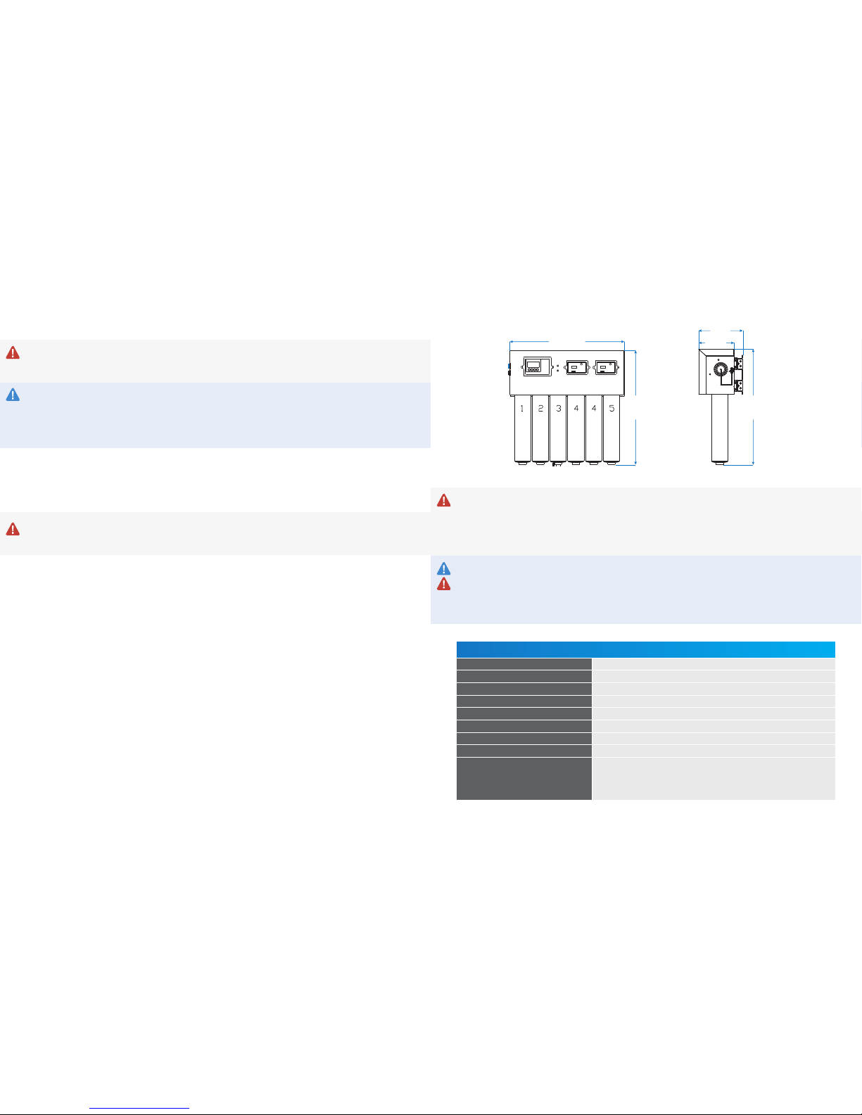
SPECIFICATIONS
Sterisil®System G4 Specifications
Minimum Pressure 65 PSI
Maximum Pressure 85 PSI
Minimum Temperature 45°F
Maximum Temperature 100°F
Faucets (2) Sink with space for two faucets
Plumbing Drain Standard sink or floor drain
Electrical Outlets (1) Quad outlet 110V AC, 3 amp, GFCI, within 3' from system
Mounting Space System: 20"L x 9"W x 20"H
Bladder Tank Space Tank 2G: 12"H x 9"Dia
Tank 4G: 15"H x 12"Dia
Tank 10G: 21"H x 13"Dia
Tank 14G: 23"H x 15.25"Dia
INITIAL SETUP AND BASELINE REQUIREMENTS
For the system to fit functionally in its mounting, it will require at least:
• 20” in length
• 9” in width
• 20” in height
These dimensions allow for 2” of space on all sides of the system.
DIRECT FEED SPECIFIC REQUIREMENTS (CUSTOMER SUPPLIED)
• Centrally installed within the dental office, the furthest chair should not exceed 50’ from the system.
• No brass or copper plumbing components may be used downstream of the system.
• Recommended use of PVC APEX A FIRE Rated tubing for delivery of dental water.
• Source water bypass should be installed by a plumber or technician to bypass the system if
necessary.
®
STERISIL SYSTEM
17- 5/8”
17- 3/16” 17- 3/16”
5- 1/2”
6- 7/8”

54 GP8002.AGP8002.A
Bottle Fill Installation
Direct Feed Installation
PHASE 1: UNPACKING AND INVENTORY
Carefully unpack the contents of the boxes. The standard Sterisil®System G4 configuration is shipped
in three boxes. One box will include the G4 along with the installation manual, warranty registration
card, system mount, and assorted bags containing other needed items for installation. Each water
storage tank will be shipped separately.
VERIFY THERE WAS NO DAMAGE DURING SHIPMENT. IF DAMAGE IS EVIDENT, CONTACT THE
SHIPPING COMPANY IMMEDIATELY.
TOOLS
Tools required for installation:
• Phillips head screwdriver
• Standard open end/box end wrenches ranging from ½” to ¾”
• Small to medium size adjustable wrench
• Standard hex key set
• Box knife
• Hand drill
• Phillips driver bits
• Universal drill bits: sizes 1/8” to ½” standard
• Level
• Schrader valved pressure gauge
• Low volume air pump
INVENTORY ITEMS MAY VARY DEPENDING ON SYSTEM SELECTION AND SPECIFIC PARAMETERS.
BOX 1:
• Sterisil®System G4
• System mount (slide or hinged)
• Bag: (Manual, packing list, faucet stickers, tank stickers and warranty card)
• 10 ft 3/8” tubing
• 40 ft 1/4” tubing
• Autoclave Faucet (white) and Dental Faucet (chrome) w/ 1/4” to 7/16” faucet connectors
• Cartridges (Stage 1, 2, 3, 4 [x2], 5)
• Permeate Pump
• Blank Cartridge, clip and mounting screws
• UV Light transformer
• Large bag: Drain Saddle Valve, thread tape, Permeate Pump clip, 1/4” pressure gauge x2, 3/8”
pressure gauge, Flow Sensor, Flow Restrictor, modular couplers, stem elbow x3, Dental/Autoclave
Discs, cables and RJ-12 connectors.
• Small bag: #10x1” mounting screws x8, sheet rock plastic anchors x8, supply tee, 1/4” union tee, 1/4”
Tank Ball Valve, 3/8” Tank Ball Valve, Inline Ball Valve and Single Check Valve.
BOX 2:
Dental Water Storage Tank
BOX 3:
Reserve Water Storage Tank
RESERVE
WATER
DENTAL
WATER
STERISIL® SYSTEM
SINK WATER
SUPPLY
1/4” LINE
3/8” LINE
1/4” LINE
1/4” LINE
1/4” LINE
1/4” LINE
SINK
DRAIN
BAutoclave/Dental Faucet W/disc
C7/16” - 1/4“ UNS
D1/4” Quick connect fitting
EMunicipal coldwater feed
F3/8” tank valve
G1/4” tank valve
HDental water tank
I1/4” tee connector
JReserve water tank
KFlow meter
L 1/4” Pressure gauge
M 3/8” Pressure gauge
NSingle check valve (SCV)
OPermeate pump
PDrain saddle valve
QUV Ballast & electrical plug
RInline ball valve
S Flow restrictor
PLAN NOTES
B
CD
D
B
C
E
F
G
H
I
J
K
L
L
M
O
P
Q
NR
400ml
S
RESERVE
WATER
DENTAL
WATER
STERISIL® SYSTEM
SINK WATER
SUPPLY
1/4” LINE
3/8” LINE
1/4” LINE
1/4” LINE
1/4” LINE
1/4” LINE
SINK
DRAIN
BAutoclave Faucet W/disc
C7/16” - 1/4“ UNS
D1/4” Quick connect fitting
EMunicipal coldwater feed
F3/8” tank valve
G1/4” tank valve
HDental water tank
I1/4” tee connector
JReserve water tank
KFlow meter
L 1/4” Pressure gauge
M 3/8” Pressure gauge
NSingle check valve (SCV)
OPermeate pump
PDrain saddle valve
QUV Ballast & electrical plug
RInline ball valve
S Flow restrictor
PLAN NOTES
D
B
C
E
F
G
H
I
J
K
L
L
M
O
P
Q
N
NR
SUPPLIED BY CUSTOMER - BYPASS MODE SHOWN
400ml
S

76 GP8002.AGP8002.A
PHASE 2: MOUNTING AND PERIPHERAL COMPONENTS
CONSIDERATIONS PRIOR TO MOUNTING
The location of your Sterisil®System G4 needs the following considerations:
• Distance to the water supply
• Leave enough slack in tubing to account for mounting configurations
• Accessibility to digital monitors
• UV Light replacement, allow 12” for clearance
• Cartridge clearance
• Distance to the electrical outlets
• Drain location for the brine line
• Placement location for the storage tanks
• Type of system mounting device: Slide or Hinged mount
SLIDE MOUNT
The system will come with the slides affixed in the correct
direction for proper maintenance. Please consider the
orientation of the slides and affix the slide mount to the
wall mounting plate before you start.
Affixing the Slide Mount to the Wall
• Remove the system off of the slide mount.
• Take your slide mounting plate and mark your holes.
• Screw the mounting plate to the wall and ensure it is
level.
Securing the G4 to the Slide Mount
• Take the system and line up the rails on the back of the
system plate to the slides on the mounting plate. Slide
the unit until you hear the rails snap into place.
• Verify it is level.
HINGED MOUNT
The system will come with the hinges affix in the correct
direction for proper maintenance. Please consider the
orientation of the hinges and affixing the hinged mount to
the wall mounting plate before you start.
Affixing the Hinged Mount to the Wall
• Remove the system from the mount.
• Take your hinged mounting plate and mark your holes.
• Screw the mounting plate to the wall and ensure it is
level.
Securing the G4 to the Hinged Mount
• Take the system hinges and affix them to the side of the
mounting plate. Push to establish a connection.
• Verify it is level.
PERIPHERAL COMPONENTS
Peripheral components - No more than 50 feet from the system.
WATER STORAGE TANKS
Storage tank sizes may differ with customer specifications and needs. Note: tank sizes will vary
depending on Stage 5 selection or pre-install requirements. As a default, the Reserve Tank will be the
larger of the two. Storage tanks must be mounted within 50 feet of the system to maintain optimal
water pressure. Set storage tanks in desired locations. A common location is under a sterilization
center sink.
• Take each tank and wrap the threads on top of the tanks with thread tape (included). Install the 3/8”
valve and hand tighten it to the larger Reserve Tank. Do not over tighten this valve.
• Repeat this process with the 1/4” valve for the Dental Water Tank.
• Ensure the pressure of the tanks is between 8–10 psi using a Schrader valved pressure gauge.
FAUCET(S) INSTALLATION
The bottle fill configuration includes a white Autoclave Faucet and a chrome Dental Faucet. Dental
water is always plumbed to the chrome faucet. Typical mounting location is on a counter-top extended
over a sink.
Direct feed systems only use the white Autoclave Faucet. Dental water is fed directly to the dental unit
hand pieces.
COUNTER-TOP MOUNT
Faucet assembly instructions are located on the back of the faucet
box.
• Do not use the compression fittings provided. Instead, use the
provided push-fit 1/4” to 7/16” faucet connectors.
• Drill a 5/8” hole at the desired location.
• Place the faucet through the hole and mount using the hardware
(included).
• Place the under-sink mounting washer, plastic gasket, lock
washer, and install the nut (included in box) and hand tighten.
• Wrap the threads with thread tape, and install faucet connectors.
PHASE 3: CARTRIDGES
• Remove the yellow cap from the top of the cartridges, and write the install date with a permanent
marker.
• Start by inserting the cartridges into the system from left to right beginning with Stage 1. Please
note, there are two Stage 4 Cartridges. They will both be positioned interchangeably in ports 4 and 5.
• Once all cartridges are installed, remove the brine plug from the bottom of the Stage 3 Cartridge.
• Install the stem elbow.
• The bottom of Stage 3 will be used in future installation steps.
• Mount the Blank Cartridge clip on the wall near the system and place the Blank Cartridge in the clip.
• Please note, the Blank Cartridge is essential for troubleshooting possible blockages inside the system.
Back of system with slide rails installed
Back of System with Hinge Plates installed
Front of Sliding Mount Plate
Front of Hinged Mounting Plate
LED
Data
Wire
Remote
Bracket
Faucet Alarm
(optional)
Mounting Washer
Lock Washer
Faucet
Connector
Plastic Gasket
Nut
Option 1: Counter Top Mount
displaying 5/8” Hole
(Counter Thickness Varies)
Option 2: Remote Bracket display-
ing Screws & Anchors

98 GP8002.AGP8002.A
PHASE 4: SOURCE WATER AND TUBING
Ensure the source water to the Sterisil®System G4 remains closed until the procedure calls for it to be
turned on.
SOURCE WATER CONNECTION
Supply Tee
• Turn off the water on the municipal supply line.
• Remove the existing hose, wrap the supply tee threads with thread tape,
and install the supply tee on the cold water supply. Tighten the tee with a
wrench. Hot water should not be used to feed the Sterisil®System G4. For
now the main valve will remained closed.
TUBING CONNECTIONS
To make a connection with quick connect fittings, simply push the tubing
into the fitting until it stops. When making cuts, be sure to cut at a right
angle to the tubing itself, and inspect the ends for burrs. Be sure to factor
any movement in the system into the tubing length so as to not put tension
on ports or components.
Source Water: (Supply Tee to Source Port) (Red fitting indicator)
OPTIONAL ADD-ONS: Booster Pump and Pre-filter Kit, see pages 11-12.
• Insert the white 1/4” tubing into the supply tee. The other end of this tubing will run to the “SOURCE”
port on the side of the system.
• Cut and install a 1/4” Inline Ball Valve.
• Cut and install Single Check Valve (SCV) on this line.
Dental Port: (Blue fitting indicator)
• Run 1/4” tubing from “DENTAL” port on the system to the 1/4” union tee.
• Run tubing from 1/4” union tee to the 1/4” tank ball valve on the Dental Water Storage Tank.
• Cut and insert 1/4” pressure gauge along tubing between connections, as close to the tank as possible.
• On the other side of the 1/4” union tee, run tubing to the chrome Dental Water Faucet.
• Direct Feed System: Run a 1/4” line from the union tee to the customer provided dental water supply
line that connects to the dental chairs.
• Cut the tubing and insert the Flow Sensor between the faucet and 1/4” union tee junction. Ensure
two stem elbows are installed on the Flow Sensor.
• Cut the tubing and insert the Single Check Valve between flow meter and the dental water supply
line. Ensure arrow is pointed towards the dental water supply line.
Autoclave Port: (Green fitting indicator)
• Run 1/4” tubing from the green “AUTOCLAVE” port on the system to the white Autoclave Faucet.
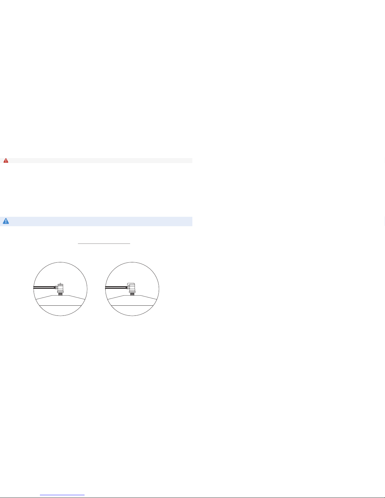
Permeate Pump:
IMPORTANT: The Permeate Pump must be mounted with the long arrow pointing up. The Permeate
Pump will not function properly if positioned sideways or upside down.
• Run 1/4” tubing from bottom of Stage 3 to “BRINE IN” on the Permeate Pump.
• Cut the tubing and insert the Flow Restrictor with the arrow pointing towards the Permeate Pump.
• Run 1/4” tubing from “BRINE OUT” on the Permeate Pump to Drain Saddle Valve (DSV).
• Note: If you have a floor drain that is accessible, you can always run tubing straight from the
“BRINE OUT” port on the pump to the floor drain. If not, you will need to install the DSV on an
existing drain pipe. Ensure tubing is secured into the drain.
• Run 1/4” tubing from “PERMEATE IN” on the Permeate Pump to black “PERMEATE IN” port on the
system.
• Run 1/4” tubing from “PERMEATE OUT” on the Permeate Pump to grey “PERMEATE OUT” port on the
system.
Drain Saddle Valve (DSV):
• Start by marking the drain pipe where you intend to drill your 1/4” hole.
The DSV will need to be before or after the peatrap.
• Attach the gasket and mount the saddle valve with the provided nuts
and bolts to the drain pipe.
• Once the DSV is properly mounted remove the gray collet from the
hole.
• Drill through the hole into the drain pipe.
• When you drill the hole, be sure not to drill through the other side of
the drain pipe.
• Clear any metal shavings from the hole, then reinsert the collet.
• Run 1/4” line from “BRINE OUT” on the Permeate Pump to the DSV.
Reserve Port: (Yellow fitting indicator)
OPTIONAL ADD-ONS: Pressure switch from Booster Pump, see page 12.
• Run a 3/8” line from the yellow “RESERVE” port on the system to the 3/8” Tank Ball Valve on the
Reserve Water Storage Tank.
• Cut and insert the 3/8” pressure gauge, as close to the tank as possible.
PHASE 5: ELECTRICAL AND OPERATIONAL TEST
ELECTRICAL
Connect all flat, 4-wire data standard power cords using color code and labels attached to the wires.
Direct Feed System will not include a chrome Dental Faucet, Dental Modular Coupler or Data Cable.
16
Autoclave
Modular Coupler
Flow Meter
Modular
Coupler
Sterisil® System
Power Cord
UV Lamp Power
Cord and
Transformer
(black)
Dental Modular
Coupler
1110 GP8002.AGP8002.A
OPTIONAL ADD-ONS
PRE-FILTER KIT (OPTIONAL COMPONENT)
Considerations:
Account for a minimum of 2” clearance at the bottom for future filter replacements.
Location of Pre-filter and Inline Ball Valve diagram is on page 12.
• Turn off your source water.
• Find a location where you can drive the screws for the bracket into the wall that will reach both your
source water line and your Sterisil®System G4 source line.
• If you have a Sterisil®Booster Pump, the Pre-filter Kit will go before the Booster Pump on the source
water line. (Reference pg. 12)
• Use a 15/64” to ¼” drill bit to drill holes in which to put the anchors.
• Drive the #10 screws into the anchors through the holes in the metal mounting bracket.
• Use the thread tape to cover the threaded end of the push-in fitting adapters.
• Twist the two quick connect fitting adapters into the two holes on the lid of the filter housing.
• Attach the filter housing to the mounting bracket using the screws provided.
• With towels ready to catch any leaking water, make a clean square cut on the source line using a
tube cutter or sharp knife. Note: If the cut is jagged, the connection will not be secure and may leak.
At the “IN” on the Pre-filter lid, insert the source water line. At the “OUT” on the Pre-filter head, insert
the water line to the system. Make sure the tubing is fully connected. You should feel it lock into
place, and you should not be able to pull it loose or have it slip out.
• Make a cut on the incoming line, and install your inline ball valve with the valve in the open position.
• Turn your source water back on.
• Check for any leaks. If there are any leaks, confirm all connections are attached securely.
• Turn your source water back off. Place one of the sediment filters in the housing, and turn your
source water back on.
CHANGING THE FILTER
Please consult with your Sterisil Dental Water Compliance Specialist to confirm your replacement
interval. Mark your calendar for the specific interval.
• Close the inline ball valves before and after the housing.
• Purge the pressure from the filter housing by depressing the red button on the top of the lid.
• Unscrew the water reservoir lid to access and replace the micron filter inside.
• Reassemble and open the inline and source water valves to restore flow to the system.
• Visually confirm water is flowing freely.
OPERATIONAL TEST
At this point, both Storage Tank Valves should be closed; meaning the ball valve knob is turned
perpendicular with the tubing going in.
• Plug in the UV Light Transformer and verify the light is functional. There will be a slight blue/purple glow.
• Open the Source Water Valve at your municipal supply.
• Confirm source water pressure is above 65 PSI and below 85 PSI.
• Leave both tanks closed.
• Turn on the Autoclave Faucet, and wait for water. Check for leaks, then turn off the faucet.
• Turn on the Dental Faucet, and look for a thin stream of water. Check for leaks, then turn off the
faucet.
• Open the Reserve and Dental Storage Tanks by turning the tank ball valve knob in line with the
tubing. Tanks will slowly begin to fill. Allow at least four hours for pressurization.
• After four hours, open the valve at the white Autoclave Faucet, and start running water. At this point,
you should be looking for leaks anywhere in the system and connecting tubing. Once you have water
at the faucet and confirmed there are no leaks, run for 2–3 minutes, then close the faucet.
• Repeat this process for the chrome Dental Water Faucet.
• Allow at least 8–12 hours for the tanks to completely fill.
• Direct Feed System: Run handpiece water at the furthest chair from the system. Check for leaks.
Note: you will not have adequate water pressure until the Dental Tank has filled.
• Check RO Quality Monitor and DI Quality Monitor readings.
• Ensure the Filter Monitor is set properly. Refer to the Maintenance Manual, pg. 13, and the Ideal
Readings and Operation document at www.sterisil.com/sterisil-system.
• Sterisil®recommends all waterlines be shocked by a plumber or technician before daily use.
Tank Ball Valve in
“closed” position
Tank Ball Valve in
“open” position
1312 GP8002.AGP8002.A
BOOSTER PUMP (OPTIONAL COMPONENT)
POWER ADAPTERS
Considerations:
• Electrical cord length and transformer.
• Pressure Switch: Ensure it is no more than 3 feet from the Reserve Storage Tank and Booster Pump.
If you have a Pre-filter Kit, install it before you install the Booster Pump.
• There are arrows on the pump to show the direction of water flow, right to left.
• Mounting on a wall is optional. The pump can also be placed on the ground.
• DO NOT plug in the power cord until you have water flowing to the pump.
Installation Steps:
• Turn off the source water and ensure both tanks are closed.
• Find a location where you can reach the source water tubing with the Booster Pump and the 3/8”
reserve line with the pressure switch. The pressure switch is installed on the “Reserve” line.
• Use a 15/64” to 1/4” drill bit to drill the pilot holes.
• Screw the #8 screws into the anchors through the holes on the Booster Pump.
• Make a clean square cut on the source line using a tube cutter or sharp knife. This cut should be
close to the Pre-filter Kit if included. There are arrows on the Pump to show the direction of water
flow. Insert the end coming from the municipal water source into the intake of the Booster Pump.
The other end of the tubing will go into the outlet on the Booster Pump. Push tubing until it is fully
inserted into each fitting.
• On the “Reserve” line, make a clean, square cut as close to the Reserve Tank as possible. Your
Pressure Switch will fit into this line. Push tubing until it is fully inserted into the fittings on the
Pressure Switch. This Switch is multidirectional.
• The Pressure Switch will connect to both the white ballast and the power cord on the Booster Pump.
• Turn your source water back on, plug in the power cord and run autoclave water for 60 seconds.
• Check for leaks. If there are leaks, ensure the pieces are properly connected.
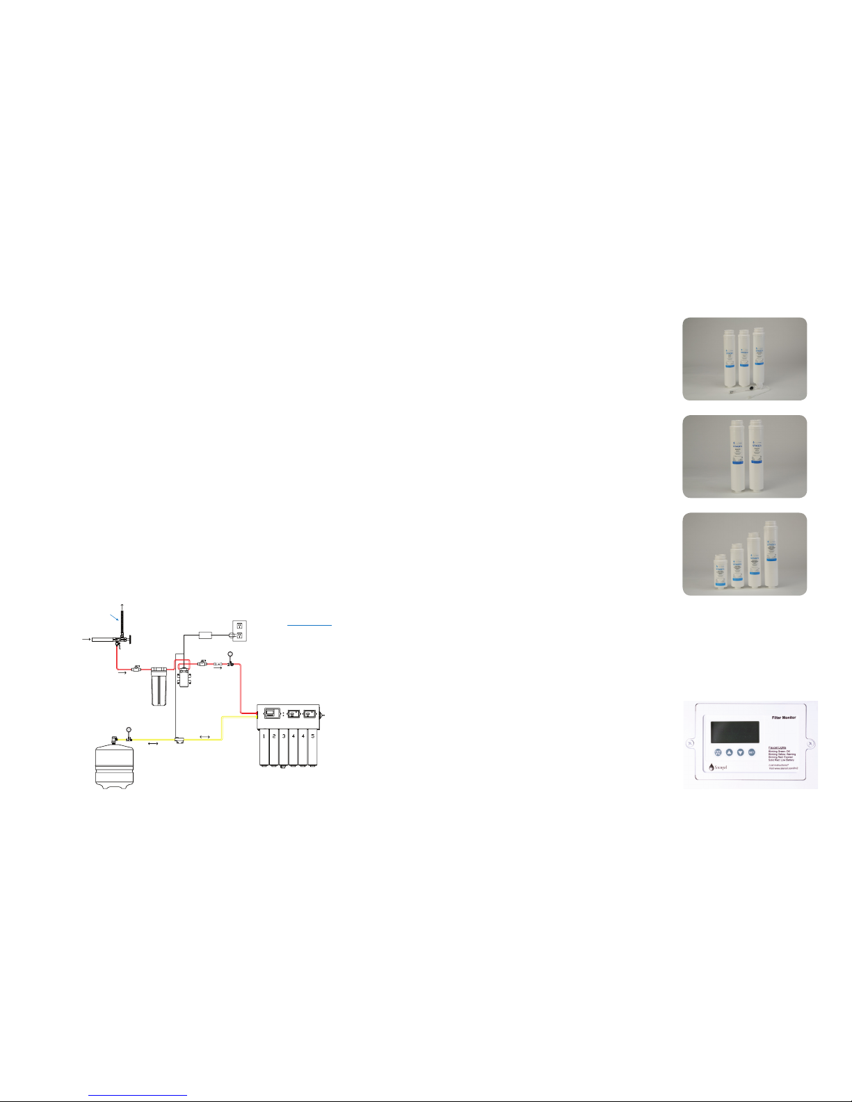
MAINTENANCE MANUAL
ANNUAL KIT (P/N: SS-AK)
Stages 1, 2, 3, and the UV Light’s lifespan are
chronological and are replaced annually from the date
of installation. Their lifespan is tracked via the Filter
Monitor on the far left side of the system. When properly
programmed, the Filter Monitor tracks the remaining
months of the cartridges and UV Light life.
STAGE 4 CARTRIDGES [P/N: SS-C4 OR (SS-DI: SS-C4 x2)]
Stage 4 Cartridge readings are based on the quality of
water coming off them. Water quality readings can be
found on the far right monitor. When the reading on
the Water Quality Monitor degrades to 10ppm on D1,
the audible alarm will sound, and the “Autoclave Water
Quality” indicator lights on the front of the system, and at
the white Autoclave Faucet Disc, will illuminate red.
At this point, the leading (left-most) Stage 4 will need to
be changed.
STAGE 5 CARTRIDGE (P/N: SS-1, SS-3, SS-7, SS-10)
Stage 5 Cartridge lifespan is based on liters of dental
water used. The Sterisil®System G4 is equipped with
a Flow Meter and liter counter. Together they track the
number of liters of dental water used. When the Filter
Monitor is properly programmed, an audible alarm will
sound. The “Dental Water Quality” indicator light on
the system and the Dental Water Faucet Disc LED will
illuminate red. A yellow light indicates a 90% capacity and a new Stage 5 should be ordered.
LOG READINGS (METHODOLOGY)
Because much of the system health is based on rates of reduction, it is important to log and monitor
water quality readings. Notating the water quality readings for the Source, RO, D1, and D2 will expedite a
solution if the need arises to contact Sterisil customer service.
FILTER MONITOR (FAR LEFT)
The Filter Monitor, when properly programmed, tracks the
remaining lifespan in months for stages 1, 2, 3, the UV Light,
and liters used on the Stage 5 Cartridge. Month counts will
always descend from a 12 month starting point. When the
month count reaches 0, an audible alarm will sound and the
word “change” will appear in the upper portion of the Filter
Monitor. At this point, Cartridges 1-3 and the UV Light will
need to be changed.
STERISIL®SYSTEM
SINK WATER
SUPPLY
1/4” LINE
BMunicipal coldwater feed
CInline ball valve
D Pre Filter
ESingle Check valve
FBooster Pump
G3/8“ Pressure Switch
H3/8” tank ball valve
IReserve water tank
J3/8” Pressure gauge
K 1/4” Pressure gauge
PLAN NOTES
RESERVE
WATER
3/8” LINE
B
CC
D
EK
F
G
H
I
J
1514 GP8002.AGP8002.A
FILTER MONITOR (FAR LEFT) CONT.
When the batteries in the Filter Monitor are ready to be changed, the system will beep intermittently,
and a battery icon will appear in the upper center of the Monitor display.
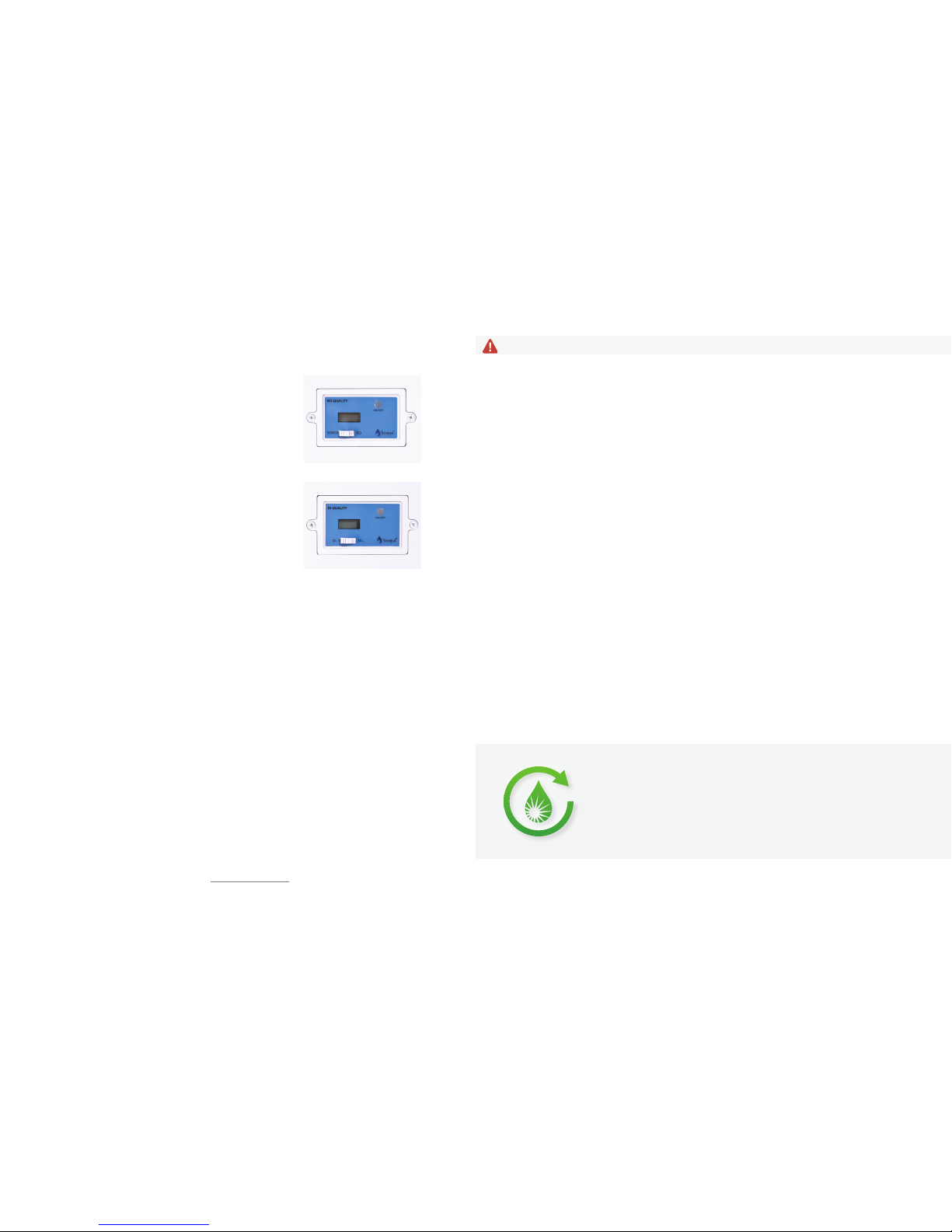
RO WATER QUALITY MONITOR (CENTER)
The RO Monitor gives both source and RO water quality
readings. To get the source water quality, ensure the Monitor
is on with the white switch in the left hand position. To get
the RO reading, ensure the Monitor is on with the white
switch in the right hand position. To attain the most accurate
reading, run the water for 30 seconds prior to taking the
reading.
DI WATER QUALITY MONITOR (FAR RIGHT)
The DI Quality Monitor gives water quality readings for both
Stage 4 Cartridges. DI-1 refers to the leading (left-most) Stage
4 Cartridge. To get the water quality reading for DI-1, ensure
the Monitor is on with the white switch to the left. DI-2 refers
to the secondary (right-most) Stage 4 Cartridge. To get the
water quality reading for DI-2, ensure the Monitor is on with
the switch to the right.
STEP BY STEP FILTER REPLACEMENT INSTRUCTIONS
Thanks to internal valving, cartridge change outs are simple and easy. It is not necessary to shut off
the source water from the supply tee. Water flow is automatically shut off when a cartridge is removed.
Please have a towel nearby for excess water in cartridges.
IMPORTANT: After installing the new cartridges and UV light, please read the Monitor Reset
Instructions to properly reset the Filter Monitor.
1. Before removing a cartridge, place a large “X” on the cartridge to be replaced to avoid any confusion
when the new cartridge is introduced.
2. If you are changing the Stage 3 Cartridge, it will be necessary to remove Stage 1 and close the
Reserve Storage Tank before replacing. To fully unscrew the Stage 3, remove the stem elbow from the
bottom of the cartridge. Simply push in on the collet and pull out on the stem elbow to remove. You
will reinstall the stem elbow by pressing the fitting into the collet once the new Stage 3 Cartridge is in
place.
3. To remove a cartridge, rotate counter clockwise until the cartridge is free of the valve head. A small
amount of water may escape during this process. Don’t panic, this is normal.
4. Before placing a new cartridge in the system, write the installation date in the space provided on the
label. Remove the yellow cap from the top of the cartridge, and rotate the cartridge clockwise into the
valve head to secure it. Ensure cartridge is fully screwed in.
5. Reprogram the Filter Monitor. Reference Reset Monitor Instructions located at www.sterisil.com.
6. The final step when changing cartridges is to run water for 60 seconds. For change outs on Stages
1-4, close the Reserve Tank and run the autoclave water. For Stage 5 change outs, close the Dental
Storage Tank, and run the dental water (Stage 5).
7. Open all tanks to finish.
8. Cartridges can either be discarded in the trash or returned to Sterisil®for recycling. For more
information on our recycling program visit sterisil.com/recycle.
2
STERISIL®RECYCLING PROGRAM
Sterisil offers a free recycling program, allowing customers to recycle their used Sterisil®
Cartidges by a click of a button. Simply visit sterisil.com/green or call us directly to
request a free shipping label.
While other companies dispose 100% of their used products to a landfill, Sterisil is able to
recycle 91% of our Straws and Cartridges. In addition to recycling, Sterisil contributes to a
greener environment by being the only dental waterline company to offer a residual
disinfectant that meets BMP compliance by not increasing the mercury output in
amalgam separators.
Do not look at the light when on. The ultraviolet light can cause eye damage.
REPLACING THE UV LIGHT
1. Unplug the bulb from the unit.
2. Use a flat head screw driver to pry out the white/clear piece and remove light.
3. Insert the new bulb until it clicks into place.
IMPORTANT: Do not touch the bulb. Grease from hands can cause damage to the lamp.
LIMITED WARRANTY
Sterisil®warrants the Sterisil®System G4 to be free from defects in parts, materials, manufacturing,
or labor for a period of one year after the device is placed in service by the end user (the “Warranty
Period”), and on select electrical components from the date of Sterisil’s Purchase. This Limited
Warranty does not include user replaceable parts required for routine maintenance of the product,
or damage resulting from abuse or neglect of the product, and covers only use of the product for
its intended purpose, and not for any other use. End users should contact Sterisil or an authorized
distributor for claims arising during the Warranty Period. Sterisil reserves the right to repair or replace,
in its discretion, any product that may exhibit a defect during the Warranty Period. Please note that the
bladder tanks need to be replaced approximately every 2 years.
EXCEPT FOR THE FOREGOING LIMITED WARRANTY, ALL Sterisil®PRODUCTS ARE SOLD “AS IS.”
THE FOREGOING LIMITED WARRANTY IS EXCLUSIVE AND IN LIEU OF ALL OTHER WARRANTIES,
EXPRESS OR IMPLIED, INCLUDING BUT NOT LIMITED TO THE IMPLIED WARRANTIES OF
MERCHANTABILITY AND FITNESS FOR A PARTICULAR PURPOSE.
Sterisil®shall not be liable to any user of any product, or any other person, for any indirect, special,
incidental, exemplary or consequential damages (including, without limitation, lost profits) resulting
from use or inability to use any Sterisil product, arising from any cause of action whatsoever, including
contract, warranty, strict liability, or negligence, even if Sterisil has been notified of the possibility of
such damages. Under no circumstances shall the liability of Sterisil to the user or any other party
exceed the purchase price of the product. No action under the foregoing limited warranty may be
brought more than one (1) year after the expiration of the Warranty Period. Exclusive subject matter and
personal jurisdiction for all disputes arising under this Limited Warranty shall be in the El Paso County
District Court in Colorado Springs, Colorado.
16 GP8002.A
16
835 S. HWY 105, SUITE D
PALMER LAKE, CO 80133
719 622 7200 | WWW.STERISIL.COM
Table of contents
Other Sterisil Water Filtration System manuals

Popular Water Filtration System manuals by other brands


Nano Soft Water
Nano Soft Water 9 Stage LG Re-Mineralizer Installation & service manual

3M
3M 3MWTS100 Installation and operating instructions

Fumex
Fumex LF 50 Instructions for use

Festo
Festo MS-LFM-...-DP Series operating instructions

Oase
Oase Filtral 1500 UVC operating instructions

Oase
Oase BioPlus 50 operating instructions


