Emperor PWCRO User manual

Penguin Water Whole House
RO
224-PWCRO-XXXX

Table of Contents
Unpacking / Inspection .............................................................................................. 3
Safety Guide ...................................................................................................... 3
Proper Installation ..................................................................................................... 4
Component Identification .......................................................................................... 6
Specifications .......................................................................................................... 12
Rejection, Recovery & Flow Rates .......................................................................... 17
System Connections, Requirements and Guidelines .............................................. 18
Electrical Connections ............................................................................................. 22
Pre-Filtration ............................................................................................................ 23
Pump ................................................................................................................ 23
Membranes ...................................................................................................... 23
UV Light Sleeve and Bulb ................................................................................ 24
Membrane Element ................................................................................................. 25
Tank Level and Pre-treatment Lockout Wiring ........................................................ 27
Anti-Scalant Filling and Settings ............................................................................. 29
RO Start-Up ............................................................................................................. 32
75% Recovery System Adjustment .................................................................. 33
Operating Do's and Don'ts ...................................................................................... 35
Low Pressure Switch ............................................................................................... 36
Pump Throttle Valve ......................................................................................... 36
Adjusting Throttle Valve ................................................................................... 37
Membrane Removal & Replacement ...................................................................... 38
Membrane Flow Overview ............................................................................... 41
Temperature Correction Factors For Membranes ................................................... 45
System Flow Diagram ............................................................................................. 47
Typical System Layout ............................................................................................ 51
Controller Programming Options ............................................................................. 52
Electrical Schematic ......................................................................................... 56
Glossary of Terms ................................................................................................... 57
Warranty .................................................................................................................. 59
2

Unpacking / Inspection
Be sure to check the entire RO system for any shipping damage or parts loss. Also note
damage to the shipping cartons. Contact Penguin Water to report any shipping damage
within 24 hours of delivery. Claims made after 24 hours may not be honored.
Safety Guide
• Check and comply with your provincial /
state and local codes. You must follow
these guidelines
• Use care when handling the RO system.
• The RO System works on 220 volt - 60
Hz 1PH electrical power only.
•DO NOT exceed 150 psi on the pump or
membrane pressure gauge. Damage or
injury could occur as a result of exces-
sive pressure.
3
Proper Installation
This RO system must be properly installed and located in accordance with the Installation
Instructions before it is used or the warranty will be void.
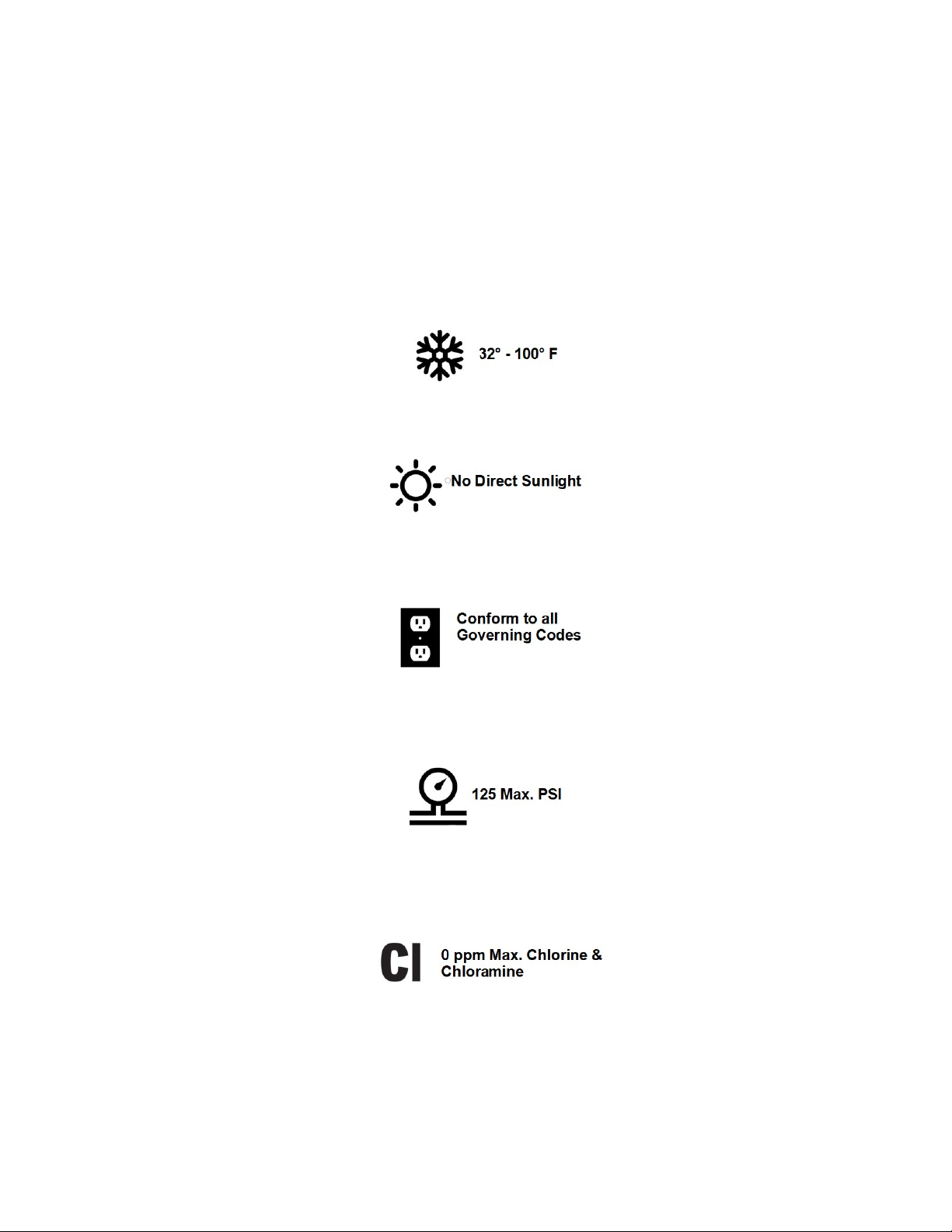
•Do not install or store where it will be exposed to temperatures below freezing or ex-
posed to any type of weather. Water freezing in the system will break it. Do not attempt
to treat water over 100°F.
•Do not install in direct sunlight. Excessive sun or heat may cause distortion or other
damage to non-metallic parts.
• Properly ground to conform with all governing codes and ordinances. Use only lead-
free solder and flux for all sweat-solder connections, as required by state federal co-
des.
• Maximum allowable inlet water pressure is 125 psi. If daytime pressure is over 80 psi,
night time pressure may exceed the maximum. Use a pressure reducing valve (PRV) to
reduce the pressure.
• RO membranes will degrade in the presence of chlorine or chloramines. In these condi-
tions, it is wise to consider purchasing a carbon filter system with a chlorine reducing
media. Contact Penguin Water for chlorine and chloramine removal equipment.
4

•Warning: Discard all unused parts and packaging material after installation. Small
parts remaining after the installation could be a choke hazard.
5
Component Identification
1. Solenoid Valve - Turns ON/OFF Feed
Water Supply when the tank input cir-
cuit is opened.
2. 5 Micron Sediment Pre-Filter - Re-
moves Sediment from the Feed Water
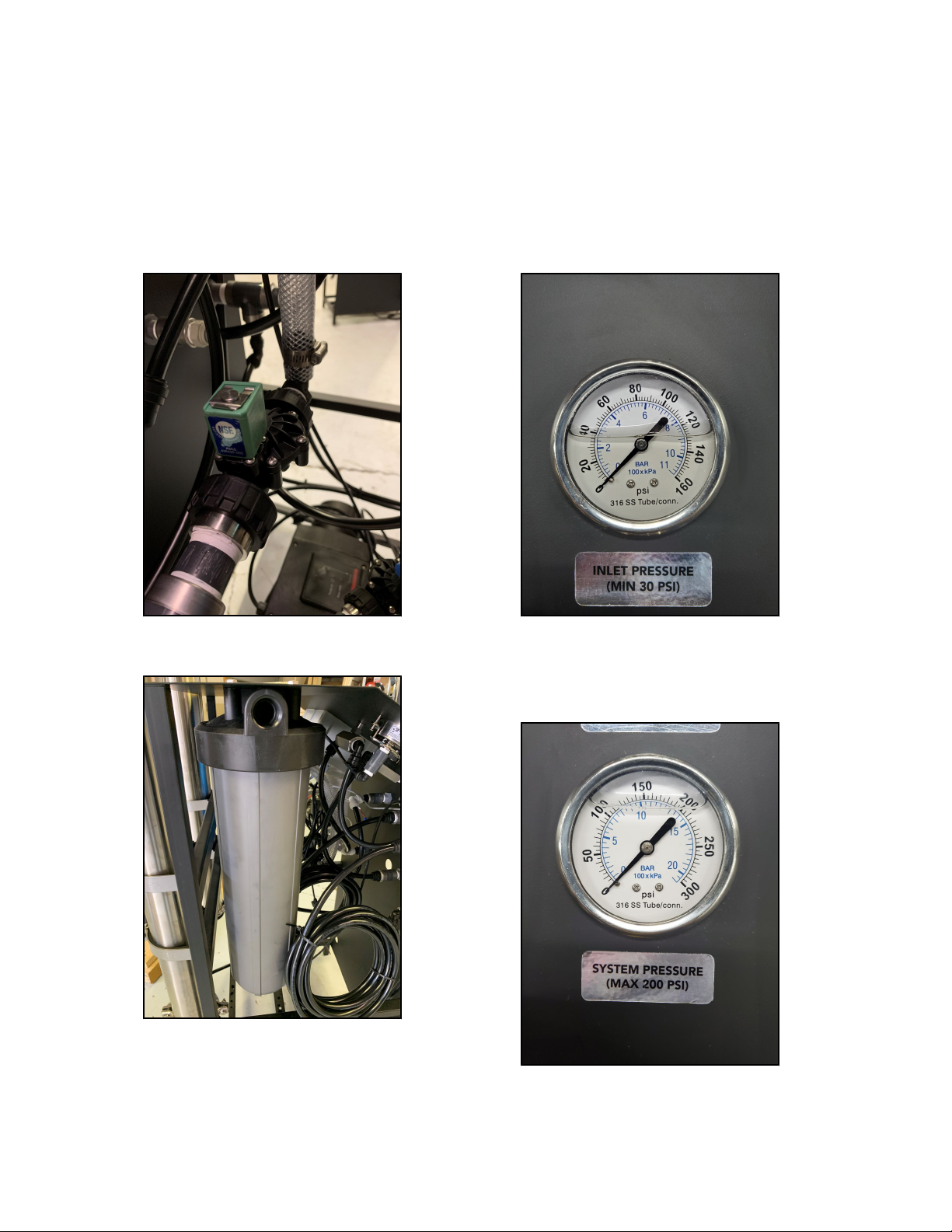
3. Pre-Filter Pressure Gauge - Monitors
Feed Water Pressure prior to the Pre-
Filter
4. Pump Pressure Gauge - Monitors the
Membrane/Pump pressure during op-
eration. WARNING! Do not exceed
150 psi.
6
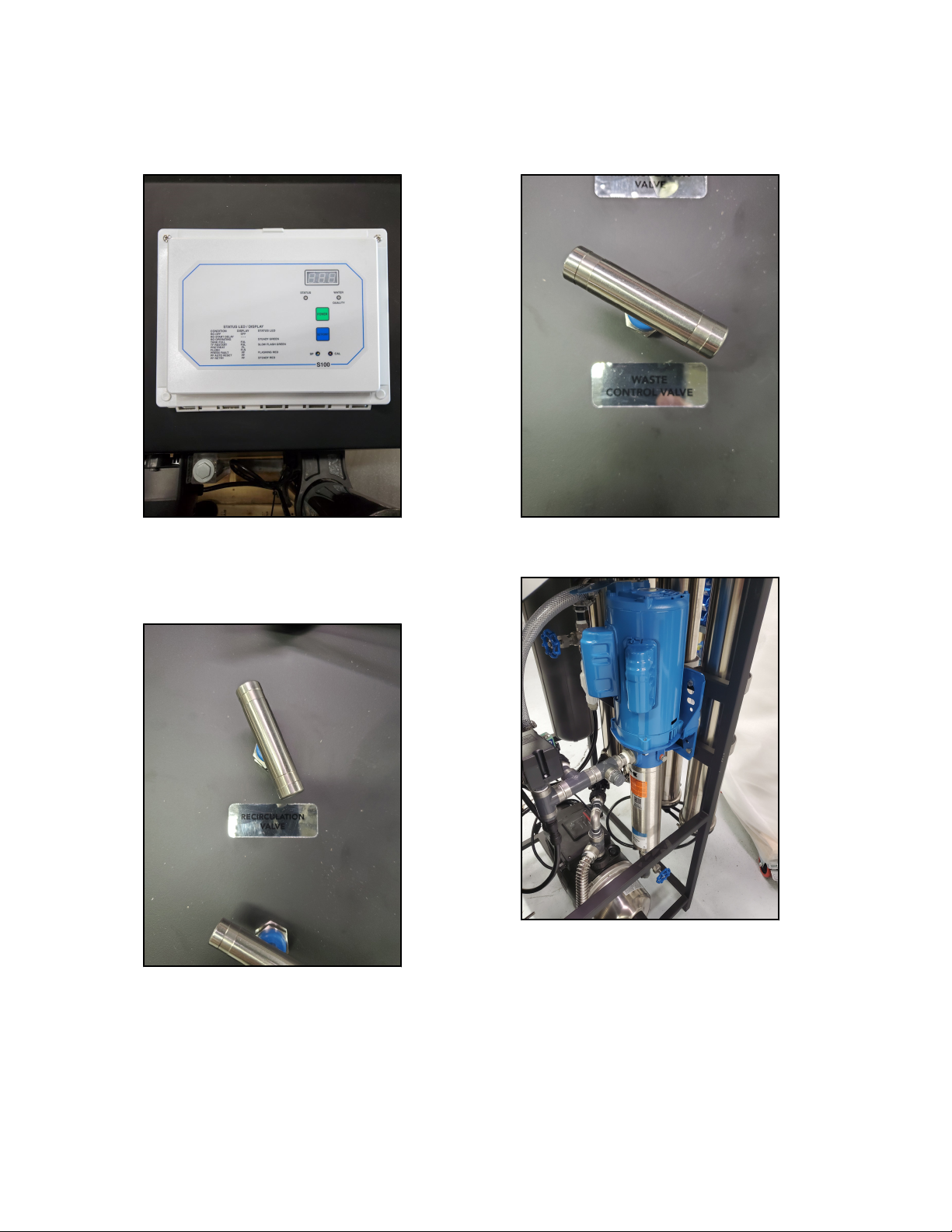
5. Computer Control - The RO Controller
Controls ON/OFF Function as well as
Fail Safe Switches.
6. Recycle/Recirculation Valve - Controls
the amount of Concentrate Water that
is fed back to the Membranes for Re-
cycle.
7. Concentrate/Waste Valve - Controls
the amount of Concentrate Water go-
ing to the drain for waste.
8. Pump and Motor - Boosts the Feed
Water Pressure to the Membranes.
7
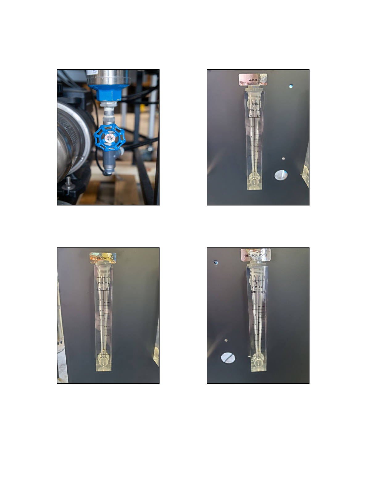
9. Throttle Valve - Adjusts the Boost
Pressure to the Membranes. WARN-
ING! Do not exceed 150 psi.
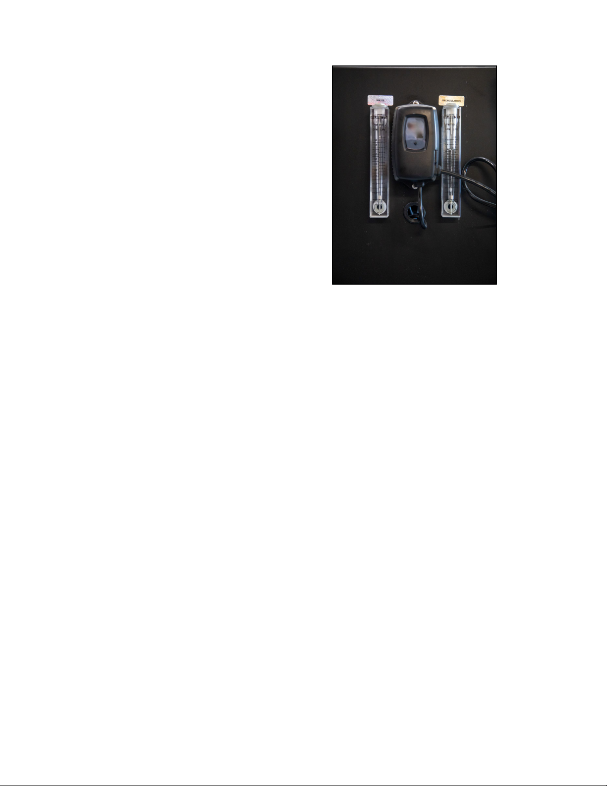
10. Permeate/Product Flow Meter - Moni-
tors the amount of Permeate Water go-
ing to the storage or distribution sys-
tem.
11. Concentrate Flow Meter - Monitors the
amount of Concentrate Water going to
drain.
12. Recycle/Recirculation Flow Meter -
Monitors the amount of Concentrate
Water being recycled to the Mem-
branes.
8

13. Low Pressure Switch - Shuts the sys-
tem down as a fail safe in a Low Feed
Water Pressure Condition. This pres-
sure switch is in the RO Controller.
14. Membrane Pressure Vessels - Holds
the Membranes.
15. Power Supply Cord
16. Injection Pump Electrical Connection
9
17. Tank Level or Pressure Shutoff and
Pre-treatment Lockout Connections.
WARNING! This input is a NO VOLT-
AGE dry contact. DO NOT apply
voltage to this input!
18. Re-pressurization Pump - Pressurizes
the water from the Storage Tank to
supply the plumbing distribution sys-
tem.
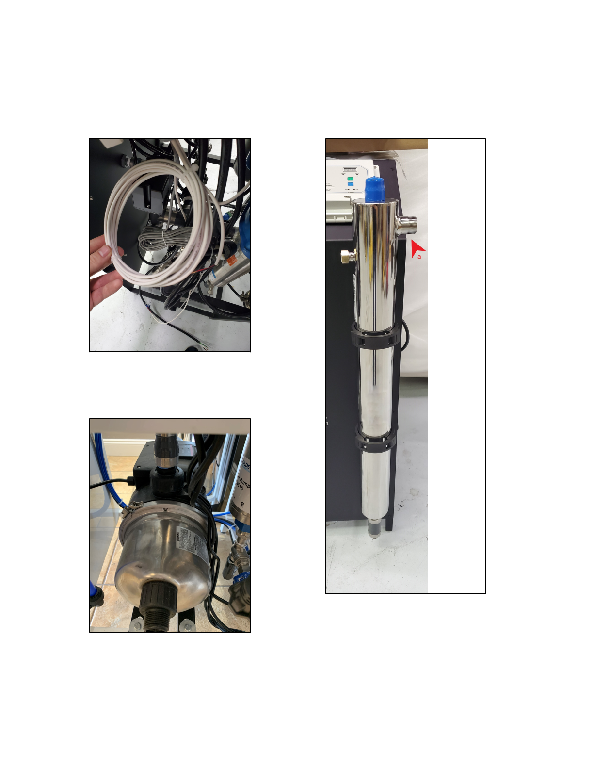
19. UV Light - Used to destroy bacteria
that may be in the water prior to the
plumbing system. (Final Connection to
Plumbing Distribution System marked
as "a")
10
20. UV Controller - Monitors the UV light
performance and bulb life.
11
Specifications
Table 1. PWCRO-2000
Design Vessels
Configuration Single Pass Vessel Array 1
Feed Water Source City or Well Water Vessel Quantity 1
Standard Recovery Rate 31.5%
Recovery with Concentrate Recycle Up to 75%
Rejection and Flow Rates Pumps
Nominal Salt Rejection % 98.5 Pump Type Multi-Stage
Permeate Flow* gpm (lpm) 1.38 (5.22) Motor HP (kw) 1.5 (1.10)
Minimum Feed Flow gpm (lpm) 4.38 (16.62) RPM @ 60 (50Hz) 3450 (2900)
Maximum Feed Flow gpm (lpm) 6.00 (22.70)
Minimum Concentrate Flow gpm
(lpm)
3.00 (11.36)
Connections Electrical
Feed inch 1 FNPT Voltage 220V 60Hz
1PH
Permeate Inch 1/2" Tubing Voltage Amp Draw 8.3
Concentrate Inch 1/2" Tubing
Membranes System Dimensions
Membrane Per Vessel 1 L x W x H inch (cm) 25 x 25 x 60
(63.5 x 63.5 x
152.4)
Membrane Quantity 1 Weight lb. (kg) 300 (136)
Membrane Size 4" x 40" (4040)
Operating Limits
Maximum Feed Temperature °F (°C) 105 (40.96) Maximum Free Chlorine
ppm
0
Minimum Feed Temperature °F (°C) 40 (4.44) Maximum TDS ppm 2000
Maximum Ambient Temperature °F
(°C)
120 (48.89) Maximum Hardness
gpg
< 1
Minimum Ambient Temperature °F
(°C)
35 (1.66) Maximum pH (Continu-
ous)
11
Maximum Feed Pressure psi (bar) 85 (5.86) Minimum pH (Continu-
ous)
3
Minimum Feed Pressure psi (bar) 35 (2.41) Maximum pH (Cleaning
30 Min)
12
Maximum Operating Pressure psi
(bar)
150 (10.34) Minimum pH (Cleaning
30 Min)
2
Maximum SDI Rating < 3
Maximum Turbidity NTU 1
12

Table 2. PWCRO-4000
Design Vessels
Configuration Single Pass Vessel Array 1:1
Feed Water Source City or Well Water Vessel Quantity 2
Standard Recovery Rate 48%
Recovery with Concentrate Recycle Up to 75%
Rejection and Flow Rates Pumps
Nominal Salt Rejection % 98.5 Pump Type Multi-Stage
Permeate Flow* gpm (lpm) 2.78 (10.52) Motor HP (kw) 1.5 (1.10)
Minimum Feed Flow gpm (lpm) 5.78 (21.88) RPM @ 60 (50Hz) 3450 (2900)
Maximum Feed Flow gpm (lpm) 9.00 (34.07)
Minimum Concentrate Flow gpm
(lpm)
3.00 (11.36)
Connections Electrical
Feed inch 1 FNPT Voltage 220V 60Hz
1PH
Permeate Inch 1/2" Tubing Voltage Amp Draw 8.3
Concentrate Inch 1/2" Tubing
Membranes System Dimensions
Membrane Per Vessel 1 L x W x H inch (cm) 25 x 25 x 60
(63.5 x 63.5 x
152.4)
Membrane Quantity 2 Weight lb. (kg) 340 (154.2)
Membrane Size 4" x 40" (4040)
Operating Limits
Maximum Feed Temperature °F (°C) 105 (40.96) Maximum Free Chlorine
ppm
0
Minimum Feed Temperature °F (°C) 40 (4.44) Maximum TDS ppm 2000
Maximum Ambient Temperature °F
(°C)
120 (48.89) Maximum Hardness
gpg
< 1
Minimum Ambient Temperature °F
(°C)
35 (1.66) Maximum pH (Continu-
ous)
11
Maximum Feed Pressure psi (bar) 85 (5.86) Minimum pH (Continu-
ous)
3
Minimum Feed Pressure psi (bar) 35 (2.41) Maximum pH (Cleaning
30 Min)
12
Maximum Operating Pressure psi
(bar)
150 (10.34) Minimum pH (Cleaning
30 Min)
2
Maximum SDI Rating < 3
Maximum Turbidity NTU 1
13
Table 3. PWCRO-6000
Design Vessels
Configuration Single Pass Vessel Array 1:1:1
Feed Water Source City or Well Water Vessel Quantity 3
Standard Recovery Rate 58%
Recovery with Concentrate Recycle Up to 75%
Rejection and Flow Rates Pumps
Nominal Salt Rejection % 98.5 Pump Type Multi-Stage
Permeate Flow* gpm (lpm) 4.16 (15.80) Motor HP (kw) 1.5 (1.10)
Minimum Feed Flow gpm (lpm) 7.16 (27.20) RPM @ 60 (50Hz) 3450 (2900)
Maximum Feed Flow gpm (lpm) 14.00 (53.00)
Minimum Concentrate Flow gpm
(lpm)
3.00 (11.36)
Connections Electrical
Feed inch 1 FNPT Voltage 220V 60Hz 1PH
Permeate Inch 1/2" Tubing Voltage Amp Draw 8.3
Concentrate Inch 1/2" Tubing
Membranes System Dimensions
Membrane Per Vessel 1 L x W x H inch (cm) 25 x 25 x 60
(63.5 x 63.5 x
152.4)
Membrane Quantity 3 Weight lb. (kg) 370 (167.83)
Membrane Size 4" x 40" (4040)
Operating Limits
Maximum Feed Temperature °F (°C) 105 (40.96) Maximum Free Chlor-
ine ppm
0
Minimum Feed Temperature °F (°C) 40 (4.44) Maximum TDS ppm 2000
Maximum Ambient Temperature °F
(°C)
120 (48.89) Maximum Hardness
gpg
< 1
Minimum Ambient Temperature °F
(°C)
35 (1.66) Maximum pH (Continu-
ous)
11
Maximum Feed Pressure psi (bar) 85 (5.86) Minimum pH (Continu-
ous)
3
Minimum Feed Pressure psi (bar) 35 (2.41) Maximum pH (Cleaning
30 Min)
12
Maximum Operating Pressure psi
(bar)
150 (10.34) Minimum pH (Cleaning
30 Min)
2
Maximum SDI Rating < 3
Maximum Turbidity NTU 1
14

Table 4. PWCRO-8000
Design Vessels
Configuration Single Pass Vessel Array 1:1:1:1
Feed Water Source City or Well Water Vessel Quantity 4
Standard Recovery Rate 65%
Recovery with Concentrate Recycle Up to 75%
Rejection and Flow Rates Pumps
Nominal Salt Rejection % 98.5 Pump Type Multi-Stage
Permeate Flow* gpm (lpm) 5.56 (21.13) Motor HP (kw) 1.5 (1.10)
Minimum Feed Flow gpm (lpm) 8.56 (32.53) RPM @ 60 (50Hz) 3450 (2900)
Maximum Feed Flow gpm (lpm) 14.00 (53.00)
Minimum Concentrate Flow gpm
(lpm)
3.00 (11.36)
Connections Electrical
Feed inch 1" FNPT Voltage 220V 60Hz 1PH
Permeate Inch 1/2" Tubing Voltage Amp Draw 8.3
Concentrate Inch 1/2" Tubing
Membranes System Dimensions
Membrane Per Vessel 1 L x W x H inch (cm) 25 x 25 x 60
(63.5 x 63.5 x
152.4)
Membrane Quantity 4 Weight lb. (kg) 400 (181.44)
Membrane Size 4" x 40" (4040)
Operating Limits
Maximum Feed Temperature °F (°C) 105 (40.96) Maximum Free Chlor-
ine ppm
0
Minimum Feed Temperature °F (°C) 40 (4.44) Maximum TDS ppm 2000
Maximum Ambient Temperature °F
(°C)
120 (48.89) Maximum Hardness
gpg
< 1
Minimum Ambient Temperature °F
(°C)
35 (1.66) Maximum pH (Continu-
ous)
11
Maximum Feed Pressure psi (bar) 85 (5.86) Minimum pH (Continu-
ous)
3
Minimum Feed Pressure psi (bar) 35 (2.41) Maximum pH (Cleaning
30 Min)
12
Maximum Operating Pressure psi
(bar)
150 (10.34) Minimum pH (Cleaning
30 Min)
2
Maximum SDI Rating < 3
Maximum Turbidity NTU 1
15

*Product Flow Rates are based on equipment test parameters. ** Does not include oper-
ating space requirements
Test Parameters: 550 TDS Filtered (5 Micron), De-Chlorinated, Softened City Feed Wa-
ter, 35 psi (2.41 bar) Feed Pressure, 150 psi (10.34 Bar) (HF4 Membranes), 70 psi (4.83
bar) Operating Pressure, 77 Degrees F (25 Degrees C), Recover as stated, 7.0 pH. Data
taken after 30 minutes of operation. Low temperatures and high TDS levels will signifi-
cantly affect system’s production capabilities. Computer projections should be run for indi-
vidual applications which do not meet or exceed minimum and maximum operating limits.
16

Rejection, Recovery & Flow Rates
The Penguin Water Whole House RO reverse osmosis system is designed to produce
permeate water at the capacities indicated by the suffix in the systems name under the
conditions listed above. For example, the PWCRO-4000 produces 4000 gallons per day
of permeate water at the listed operating test conditions.
The amount of total dissolved solids (TDS) rejected by the membrane is expressed as a
percentage. For example, a 98.5% rejection rate means that 98.5% of total dissolved sol-
ids do not pass through the membrane. To calculate the % rejection, use the following for-
mula:
•% Rejection = [(Feed TDS - Product TDS) / Feed TDS] x 100
• Example: 98.5% = [(550 - 8.25) / 550] x 100
NOTE: ALL TDS FIGURES MUST BE EXPRESSED IN THE SAME UNITS, TYPICALLY
PARTS PER MILLION (PPM) OR MILLIGRAMS PER LITER (MG/L).
The Whole House RO reverse osmosis system is designed to reject up to 98.5% NaCl,
unless computer projections have been provided or stated otherwise.
The amount of permeate water recovered for use is expressed as a percentage. To calcu-
late % recovery, use the following formula:
•% Recovery = (Product Water Flow Rate / Feed Water Flow Rate) x 100
• Example: 40% = (2.78 / 7.0) x 100
NOTE: ALL FLOW RATES MUST BE EXPRESSED IN THE SAME UNITS, TYPICALLY
GALLONS PER MINUTE (GPM).
17

System Connections, Requirements and Guidelines
PLUMBING
The membranes and high pressure pumps used on Whole House RO systems require a
continuous flow of water with a minimum feed pressure of 35 psi, not to exceed 105°F
while the system is running.
FEED WATER CONNECTION
1. Locate the 1" FNPT inlet connection on the sediment filter housing.
2. Attach the inlet piping to the 1" FNPT Filter housing inlet.
NOTE: FEED LINE MUST BE MINIMUM 3/4".
PERMEATE (PRODUCT WATER) CONNECTION
1. Locate the 1/2" tubing labeled permeate and attach to the bulkhead in the top of the
storage tank. Ensure that the permeate water can flow freely with no back pressure.
Back pressure can cause irreversible damage to the membrane elements.
NOTE: ALL PERMEATE PLUMBING SHOULD BE DONE WITH PLASTIC OR
STAINLESS STEEL. SOFT METALS WILL LEACH INTO THE WATER STREAM.
CPVC, PVC, PEX AND STAINLESS STEEL ARE THE MOST COMMONLY USED
MATERIAL.
CAUTION: THE PH OF THE REVERSE OSMOSIS PERMEATE WATER WILL TYPI-
CALLY BE 1-2 POINTS LOWER THAN THE FEED WATER PH. A LOW PH CAN
BE VERY AGGRESSIVE TO SOME PLUMBING MATERIALS SUCH AS COPPER
PIPING.
18

CONCENTRATE (WASTE WATER) CONNECTION
1. Locate the 1/2" tubing labeled concentrate and attach/convey to a drain. Run the con-
centrate line to an open drain in a free and unrestricted manner (no back pressure). It
is recommended that an air gap be maintained on the drain line to prevent possible
bacterial contamination.
CAUTION: ANY RESTRICTIONS OR BLOCKAGE IN THE DRAIN LINE CAN
CAUSE BACK PRESSURE, WHICH WILL INCREASE THE SYSTEMS OPERAT-
ING PRESSURE. THIS CAN RESULT IN DAMAGE TO THE SYSTEMS MEM-
BRANES AND COMPONENTS.
19
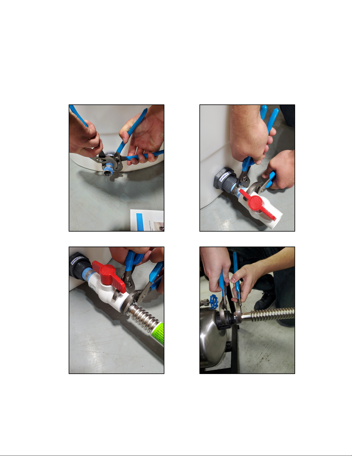
RE-PRESSURIZATION PUMP CONNECTION
1. Apply Teflon tape to the supplied 1" stainless steel nipple and install into the bulkhead
located at the bottom of the atmospheric storage tank. Tighten using two pairs of
channel locks. Then install the supplied ball valve using the same method. Locate the
1" male threaded connection on the re-pressurization pump and attach the piping
from the bottom of the storage tank. Do not turn the pump on at this point.
20
Table of contents
Other Emperor Water Filtration System manuals

Popular Water Filtration System manuals by other brands

Thinkwater
Thinkwater PROfine SILVER DRINK KIT Installation and use

HOME WATER
HOME WATER EZ CHANGE manual

Oase
Oase BioPress 4000 operating instructions

Insignia
Insignia NS-4396508-2 Quick setup guide

Everpure
Everpure E10 Installation and operation guide

Hydac
Hydac FluidAqua Mobil FAM 25 Operating and maintenance instructions


Esta
Esta VACUMAT 1000 operating instructions

amiad
amiad SAF-3000 Installation, operation and maintenance instructions

Cornelius
Cornelius QLT 180 INSTALLATION & CLEANING INSTRUCTIONS

Ecosoft
Ecosoft MO36000PECO Installer and user guide

Sears
Sears 625.3444 owner's manual

Metasys
Metasys COMPACT Dynamic Equipment Logbook Assembly, operation and maintenance