GB-12
GB
8 Read the burner pressure at the pressure test
point for pGand readjust if necessary. Measure
the λ and O
2
values with a calibrated flue gas
measuring instrument and adjust according to
the values in the table:
Gas type
Inlet
pressure
pu[mbar]
Burner
pressure
pG[mbar]
Lambda
λO[%]
min. max. max. min. max. min. max.
Natural gas L
G25 25 100 15.5 1.2 1.35 3.5 5.4
Natural gas
K gas (G+) 25 100 15.5 1.2 1.35 3.5 5.4
Natural gas
H G20 20 100 11.5 1.2 1.35 3.5 5.4
LPG butane
G 30 29 100 18.7 1.2 1.35 3.5 5.4
LPG
propane
G 31
29 100 22.0 1.2 1.35 3.5 5.4
▷
If the burner pressure is ≤ the value in the ta-
ble and the minimum λ and O
2
values are not
reached, reduce the burner pressure until the λ
and O2values are between the min./max. limits.
▷If the burner pressure is ≤ the value in the table
and the maximum λ and O
2
values are exceeded,
increase the burner pressure by a maximum
of 5%.
▷
If the measured values correspond to the details
on the type label and in the table, the heater has
been set correctly. Otherwise, continue with the
measurement and fine adjustment until the heater
is correctly set.
▷Heater adjustment is now complete.
CAUTION
To avoid damage to the heater RGA100, please
observe the following:
– The low-fire rate may only be set by author-
ized trained personnel by agreement with the
manufacturer.
▷A service form can be found inside the housing
cover. All settings for the future use of the heater
and any guarantee claims are to be kept up-to-
date on this form.
Flame signal
▷
The flame signal can be displayed when the
burner is operating.
Pressing the RESET button displays the flame
signal.
▷It is shown in coded form as a number from 0
to9. This number must be multiplied by a factor
of2. The result of this multiplication is the level
of the flame signal inµA. Example: the number 3
corresponds to a flame signal of 6–8µA.
Display Flame
current [µA] Display Flame
current [µA]
00 – 2 510 – 12
12 – 4 612 – 14
24 – 6 714 – 16
36 – 8 816 – 18
48 – 10 918...
Check the flame signal.
▷The flame signal is displayed for 20s.
Press the RESET button to exit the flame signal
display.
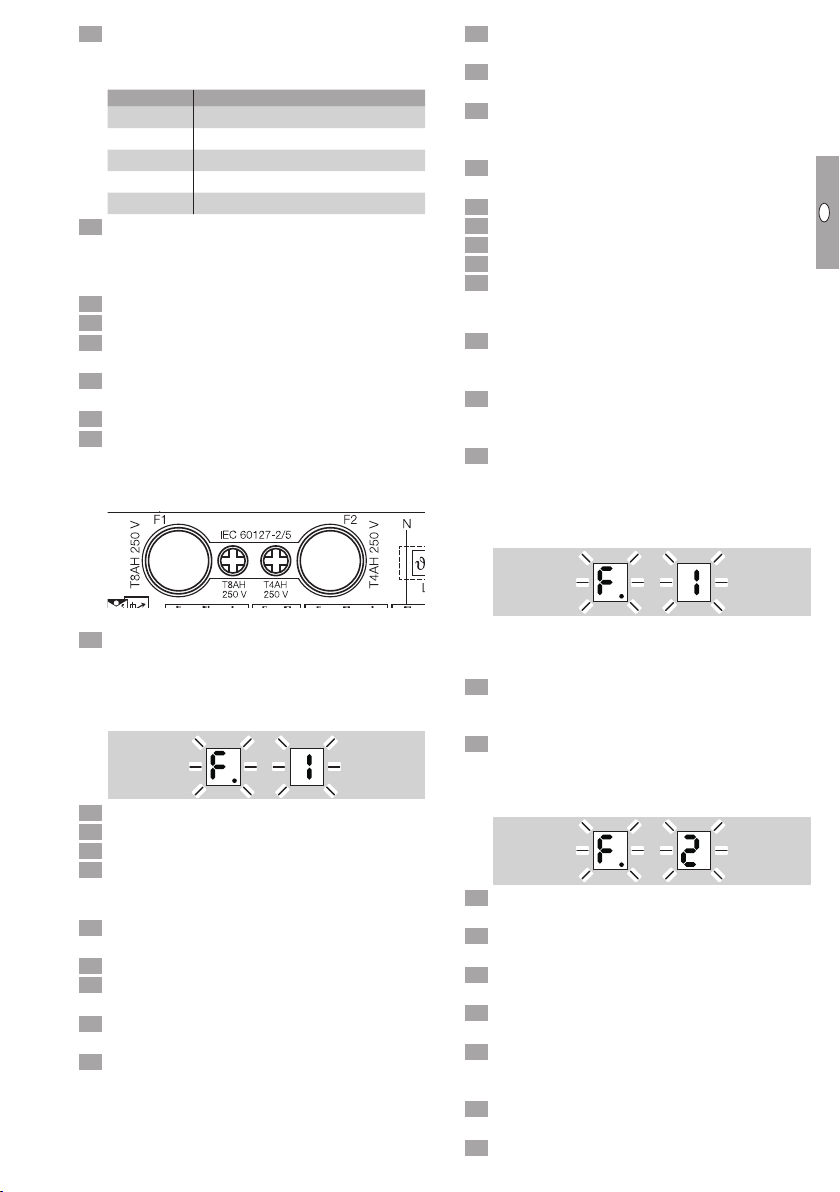
▷If the flame signal is <2µA, fault F(flame fault)
1or 2is displayed, see page14 (Assistance
in the event of malfunction).
Cleaning
CAUTION
To ensure that no damage occurs during operation
and cleaning, please observe the following instruc-
tions. Otherwise, injuries or damage to the device
may occur and/or the function of the device may
be impaired, and the manufacturer’s warranty will
be cancelled.
– Sharp-edged metal sheets. Always wear protec-
tive gloves.
– After cleaning, check that the components on
and in the heater are in good condition. The
device may only be restarted if all safety devices
have been installed and the safety functions
have been checked.
– Clean the heater once a year when used in
horticulture and at regular intervals as well as
after each fattening period when used in agricul-
ture, as described below. Inadequate or irregular
cleaning can cause the device to overheat and
can thus lead to fire damage or damage to the
device. For example, dirt particles can catch
fire and can be blown out of the heater.
▷The RGA100 is made of high-quality stainless
steel and is resistant to external influences such
as dirt and moisture.
▷It is designed so that it can be cleaned carefully
both inside and outside with a high-pressure
cleaner.
▷
The housing cover and cable glands on the
burner control unit must be closed during the
cleaning process.