Sterling CRS-3 User manual

1
INSTALLATION MANUAL
12630 US 33 N.
Churubusco, IN 46723
Ph. (260)693-1972 Fax (260)693-0602
www.sterlingwatertreatment.com
CRS-3

2
SECTION I. INTRODUCTION........................................................................3
SECTION II. SPECIFICATIONS.....................................................................3
SECTION III: PREPARATION.........................................................................4
A. Major System Components......................................................................................................4
B. Tools Recommended for Installation.........................................................................................4
C. Determine System Location......................................................................................................4
D. Prepare the Area for Installation...............................................................................................5
E. Prepare the Appliance for Installation.......................................................................................5
SECTION IV. INSTALLATION STEPS...........................................................5
A. Install the Faucet......................................................................................................................6
1. Make the Faucet Mounting Hole....................................................................................6
2. Mount the Faucet...........................................................................................................7
B. Install the Feed Water Valve and Tubing................................................................................7
C. Make Initial Tubing Connections..............................................................................................7
D. Install the Purification Assembly…………………………...........................................................8
E. Make Final Tubing Connections................................................................................................8
F. Start up the System...................................................................................................................8
G. Flush System of Particles and Check Operation......................................................................8
SECTION V: OPERATION & MAINTENANCE...................................................8
A. Normal Operation....................................................................................................................8
B. Changing Filters......................................................................................................................8
C. Installation Drawing & Parts List………………...…...……………………………………………..9
D. For Systems Equipped with Quick Connect Fittings...............................................................10
SECTION VI: TROUBLESHOTTING GUIDE......................................................11
LIMITED WARRANTY.........................................................................................12
TABLE OF CONTENTS:

3
SECTION I. INTRODUCTION
Congratulations, you have just purchased one of
the finest Drinking Water Appliances available.
Like any other fine product, this appliance requires
periodic maintenance in accordance with the
schedule outlined below.
Your new Drinking Water system uses a
combination of ultra filtration technologies to reduce
unwanted contaminants in a water supply. The
following steps combine to give you the best in
clear sparkling drinking water:
MECHANICAL FILTRATION - The sediment pre-
filter will remove the larger particles such as silt,
rust and scale. Its 5 micron (equal to 0.0002 inch)
nominal rating helps to give maximum life to the UF
Membrane and carbon filter.
CARBON BLOCK PRE FILTER - The carbon filter
is a carbon block that has coconut shell activated
carbon with a smaller pore size to increase the
range of organics removed and extend the amount
of chlorine reduction. Carbon block filter has a five
micron rating to further protect the membrane.
ULTRA FILTRATION MEMBRANE -The UF
Membrane is the heart of the filtration system. It is
designed to reduce particles, colloids, and
macromolecules down to 0.03 microns. UF
membranes have the capability of reducing
bacteria, viruses, silt, and colloids. UF membranes
are not recommended on using with biologically
unsafe water.
SECTION II. SPECIFICATIONS
TABLE A –QUALIFIED SYSTEM PERFORMANCE
Because the performance of an UF Membrane is highly dependent upon pressure, temperature and TDS, the
following should be used for comparison purposes only.
U.S. Metric
Membrane Production15,000 gallons 18,927 Liters
1Industry standards measure UF Membranes performance with no backpressure on the product water, at 65 psig
(448kPa) and 77°F (25°C). The production rate of a new Membrane can decrease by 10% per year or more, depending
upon the scaling and fouling tendencies of the Feed Water.
Recommended Filter Change Schedule*
1 - Pre-filter, QCF-S 6 Months
2 –Carbon Block Pre-filter for 6 Months
Chlorine Removal, QCF-CB
3 –Ultra Filter Membrane, 6 Months
QCF-UF
*Based on standard conditions

4
TABLE B –RECOMMENDED OPERATING LIMITS FOR FEED WATER
Specifications UF Membrane
Water Pressure 40-100 psig
TDS 2000 ppm (also mg/l) max.
Temperature 40-100°F
pH 4-11 (optimum rejection at pH 7.0 –7.5)
Turbidity 300 NTU
Chlorine 200 mg/l max.
Bacteria Must be potable**
**DO NOT USE WITH WATER THAT IS MICROBIOLOGICALLY UNSAFE OR OF UNKNOWN QUALITY.
SECTION III: PREPARATION
A. Major System Components
The following components comprise the UF Drink-
ing Water System:
1. A UF assembly consisting of the aluminum
bracket, filter housings, automatic shut-off.
2. A faucet kit.
3. A plastic tubing kit with self-piercing saddle valve
and drain clamp.
4. Other items necessary for installation may
include wood screws or machine screws for
mounting the UF assembly concrete anchors
may be required for hanging on basement wall,
additional tubing or tube connectors, and plastic
wire ties for organizing tubing.
Note: For systems equipped with Quick Connect
fittings, see page 10.
B. Tools Recommended for Installation
The following tools will cover most of the installation
sites encountered:
3/8" variable speed electric drill.
Extension work light with outlet.
Safety Glasses.
1-1/4" porcelain hole cutter kit.
1-1/4" Greenlee hole punch and 1/8" and
1/2"metal drill bits for pilot hole.
Center punch and hammer.
1-1/4" wood bit.
Assorted wood and metal drill bits including
7/32" metal drill bit.
Phillips head and flat blade screwdrivers.
1/2", 9/16" and 5/8" open end wrench.
10" Crescent wrench with jaws taped to
hold faucet.
Teflon tape.
Wide masking tape or duct tape.
Plastic tubing cutter.
Extra plastic tubing.
C. Determine System Location
The CRS-3 system can be located under a sink or
in a basement depending on space availability and
the customer’s preference. If a basement
installation is selected, additional tubing, hardware
and fittings may be needed and a hole will have to
be made from inside the cabinet, through the floor,
to the basement. Never install in an area of the
home where temperature is freezing as damage to
the system will result.

5
1) Faucet - The faucet should be placed near
the sink where drinking water is normally
obtained. Convenience of use (filling of
water pitchers and glasses), and an open
area beneath the faucet under the sink for
attaching product tubing are considerations.
A 2" diameter flat surface is required above
and below the mounting site. The thickness
of the mounting surface should not exceed
1-1/4".Watch for strengthening webbing on
the underside of cast iron sinks.
2) UF Assembly - The UF Assembly may be
mounted on either the right or left side of the
under-sink area or a cabinet. Mounting in
the basement is also an option, one
possible location is near the laundry /utility
sink where cold potable water and drain
access is handy. The mounting location
should allow adequate clearance and
accessibility for cartridge changes.
3) Feed Water Connection - The self-piercing
feed water shut off valve should be located
as close to the UF assembly as possible.
USE A POTABLE COLD WATER SUPPLY
ONLY. Softened water is preferred as it will
extend the life of the UF Membrane.
D. Prepare the Area for Installation
To save time it is often advised to call the customer
and request they clear under the sink prior to
arrival. Otherwise, remove supplies from under the
sink and stack them neatly away from the working
area. Arrange a light for the work area, if
necessary.
If a basement installation is called for, determine
where components will be located and how they will
be mounted. Special mounting brackets and
hardware may be necessary to secure the system
to a wall or ceiling joists.
Inspect cold water supply line and drain to
determine if any special fittings, in addition to what
is included in the kit, are required.
E. Prepare the Appliance for Installation
Open shipping carton and remove components.
Check that all installation parts are present which
includes the purification assembly, faucet,
installation hardware, and tubing.
SECTION IV. INSTALLATION STEPS
All plumbing should be done in accordance with
state and local plumbing codes.
NOTE: Some codes may require installation by a
licensed plumber; check with the local plumbing
authority prior to installation.
In restricted under-sink areas, it may be easier to
install the faucet first. Allow adequate tubing
lengths for any final component position.

6
A. Install the Faucet
See Figure 1 for Faucet Installation Diagram
The customer should be consulted before
determining faucet location. The faucet should be
positioned so that it empties into the sink and the
spout swivels freely for convenience.
If the sink already has a hole provided that can
accommodate the UF faucet, then no drilling is
required and you can proceed to the section on
mounting the faucet.
1. Make the Faucet Mounting Hole
IMPORTANT: It is mandatory that safety glasses
be worn during sink hole drilling operations to
prevent eye injury.
Before starting the hole making operation, always
check below the sink so that nothing interferes with
mounting the faucet such as reinforcing ribs,
support brackets or cabinet construction.
STAINLESS STEEL SINK:
Recommended tools:
Center punch
Variable speed drill and high speed drill bits.
Greenlee chassis punch 7/8” hole size
(alternate 9/16” size may be used for non air
gap faucet)
Protective gloves
Procedure:
a) Center punch a small indent at the desired
faucet location.
b) Slowly drill the required pilot hole for the
chassis punch.
c) Set up the chassis punch per instructions
and tighten nut to cut the desired hole
size.
d) Clean up sharp edges with a file if
necessary.
PORCELAIN/ENAMEL/CERAMIC ON SHEET
METAL OR CAST IRON BASE:
Recommended tools:
Variable speed drill
Relton porcelain cutter tool set 7/8" size
(alternate 9/16: size may be used for air gap
or non-air gap faucet)
Plumber’s putty
It is important to understand what is involved in this
procedure. First, the glassy layer of porcelain must
be penetrated through to the base metal. Second, a
center disc of porcelain must be removed while
protecting the surrounding porcelain against chip
ping or fracturing. Third, the base metal must be
drilled through to complete the hole.
Procedure:
a) Mark the center for the 7/8” hole
b) Form shallow putty dam around hole area
and fill with enough water to lubricate
carbide drill bit.
c) Carefully drill plot hole through
porcelain/enamel and base metal using
carbide type pilot drill.
IMPORTANT: Always operate drill with light
pressure at slow speed (300-400 rpm).
d) Insert pilot tip of spring-loaded porcelain
cutter into pilot hole.
e) Drill porcelain/enamel using spring-loaded
porcelain cutter, making certain a complete
ring has been cut through the
porcelain/enamel to the metal base.
f) Change to the metal cutter. With slow
speed and light pressure, cut away the inner
porcelain/enamel disc down to base metal.
Make certain that the cutter does not touch
outer rim of the cut porcelain/enamel.
Continue with this bit to cut through metal
until sink has been completely penetrated.
IMPORTANT: When using a porcelain cutter it
is critical to take precautions that it is always in
a sharpened condition. Dull cutters are known
to chip sinks.

7
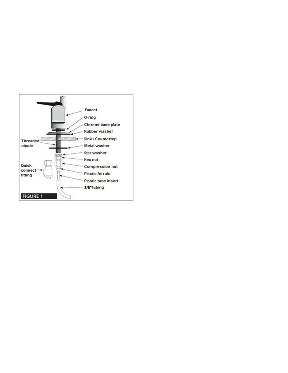
2. Mount the Faucet:
a) Familiarize yourself with all components
shown in faucet diagram.
b) Disassemble hardware from the threaded
nipple, except for chrome base plate and
rubber washer.
NOTE: Rubber washer may be replaced with bead
of plumber’s putty for neater appearance.
c) Connect length of standard 1/4" tubing to
faucet. Ensure plastic insert is in tubing.
Push on firmly until it seats.
d) Feed the threaded nipple through
sink/counter mounting hole and orient the
faucet as discussed with the customer.
e) From below sink/counter assemble the
black plastic washer, star washer and hex
nut on threaded nipple and tighten by hand.
f) After rechecking faucet orientation, tighten
hex nut (9/16" wrench or deep socket) until
faucet feels secure.
g) From above the sink make any minor
orientation corrections by turning the faucet
with a padded adjustable wrench.
h) Install plastic ferrule and compression nut
on tubing.
Note: Flats on chrome faucet may be used for
tightening with an adjustable wrench. Use care not
to mar chrome finish.
B. Install the Feed Water Valve and Tubing
The saddle tapping valve supplied is designed for
use with 3/8" to 1/2" OD soft copper supply tubing
(plain or chromed), rigid metal pipe, or CPVC
plastic pipe. Do not use with flexible ribbed supply
tubing which has too thin a wall thickness and
requires special hard ware.
Saddle Valve Installation
SOFT COPPER TUBING INSTALLATION:
1) Turn off cold water valve under the sink, or
main valve for the house.
2) Before installing saddle tapping valve, make
sure piercing lance does not protrude
beyond rubber gasket.
3) Assemble saddle tapping valve on copper
tubing. Tighten clamp.
4) To pierce soft copper tube, turn handle
clockwise until it is firmly seated. The valve
is closed in this position.
5) Turn on main supply valve to pressurize
coldwater line. Check for leaks. With a
wrench snug nut/seal around valve stem.
6) Connect one end of the tubing to the feed
water valve using brass compression nut
and plastic sleeve.
NOTE: For basement installations the existing feed
water tubing may have to be longer to reach feed
valve.
RIGID METAL PIPE AND CPVC PLASTIC PIPE
INSTALLATION:
1) Turn off cold water supply valve and drain the
line to prevent spillage.
2) Drill 3/16" hole at the desired location. To pre-
vent shock hazard, use a battery operated drill.
3) Before installing saddle tapping valve, make
sure piercing lance does not protrude beyond
rubber gasket.
4) Assemble saddle tapping valve on copper
tubing.
5) Turn saddle valve handle clockwise to close
valve. With a wrench tighten nut/seal around
valve stem.
6) When you wish to open valve and supply cold
water to the unit, turn valve handle counter
clock wise.
7) Connect one end of the tubing to the feed
water valve using brass compression nut and
plastic sleeve.
NOTE: For basement installations the existing feed
water tubing may have to be longer to reach feed
valve.
C. Make Initial Tubing Connections
It is advantageous to make some of the tubing
connections at this time, since the under-sink work
area is not so cramped and access to the
components is easier.

8
D. Install the Purification Assembly
The purification assembly is usually mounted to the
right or left sink cabinet sidewall, taking into con-
sideration the space available. Generally, the
purification assembly is positioned toward the front
for cartridge accessibility.
To mount the purification assembly elevate at least
2" off the cabinet floor and, while keeping level,
mark the location of the mounting holes on cabinet
sidewall. Make small pilot holes with an awl or drill
and screw in the two mounting screws, leaving just
enough protruding to allow bracket mounting slots
to slide over them.
NOTE: If the cabinet sidewalls are not of solid
construction, the purification assembly can be set
on the cabinet floor and held against the sidewall
with the mounting screws.
E. Make Final Tubing Connections
With all of the components in place, the final tubing
connections can be made. When routing tubing
between components, several guidelines should be
observed.
Tubing runs should generally follow the con-
tour of the cabinets rather than interfere with
the cabinet storage area.
Strive for neatness and an orderly tubing
“flow” using fasteners (e.g. insulated
staples) to secure the tubing. Cut tubing to
the desired length.
Arrange the tubing so there are no sharp
bends and leave some “play” in the tubing
for ease of servicing.
Try to keep the tubing from the purification
assembly to the faucet as short as practical
for good flow.
F. Start up the System
1) Double check that all connections are
secure.
2) Turn on feed water valve and check for
leaks. If any leaks are noted, turn off valve
and correct before proceeding.
3) Open faucet until a steady stream of water
flows. Close faucet, wait at least 5 minutes
and carefully check for leaks. Correct as
necessary.
G. Flush System of Particles and Check
Operation
1) Lift faucet handle and allow system to pass
a few gallons of water. Run water from
faucet until it flows clear. Once water runs
clear, it should be safe to drink.
SECTION V. OPERATION &
MAINTENANCE
A. Normal Operation
1) It is normal for the water to flow at a rate of
1 gpm.
B. Changing Filter
NOTE: THIS UF SYSTEM CONTAINS FILTERS
WHICH MUST BE REPLACED AT REGULAR
INTERVALS TO MAINTAIN PROPER
PERFORMANCE. USE ONLY FACTORY
APPROVED FILTERS.
Please see Page 3 for the recommended interval
for changing the filters. Local conditions may
dictate more frequent changes.
Use a drip pan to catch any water that may spill
when the filter housings are removed:
1) Close plastic supply valve located on the
inlet line of the system.
2) Open the faucet and wait for the flow to
stop.
3) The cartridges can be hinged out away from
the wall. Rotate the cartridge 1/4 turn
counter clockwise and pull down. The
cartridges can be disposed.
4) Push the new filter into the head and rotate
it clockwise ¼ turn.
5) Wipe up any spilled water.

9
C. Installation Drawing & Parts List
Ref
Part Number
Description
1
RO-DW-1
Luxury long reach faucet, non air gap,
chrome
2
4FC4
Faucet connector, ¼” tube X 7/16”
UNF
3
TU-2W
¼” OD white poly tubing, per foot
4
4SE4
Stem elbow, ¼” tube X ¼” stem
5
4MC
Male connector, ¼” tube X ¼” MNPT
6
QCF-UF
Quick-Change Filter, UF Membrane
7
QCF-CB
Quick-Change Filter, Carbon Block
8
QCF-S
Quick-Change Filter, Sediment
9
BV-101
Ball valve, ¼” tube X ¼” tube
10
F-SAD
Supply saddle valve, ¼” thread

10
D. For System Equipped with Quick Connect
Fittings
Your new UF Drinking Water Appliance may be
outfitted with new generation of user-friendly quick
connect push-in fittings. Proper use of the fittings is
shown in the diagrams.
It is important that the tubing selected for use with
these connectors be of high quality exact size and
roundness, and with no surface nicks or scratches.
If it is necessary to cut the tubing, use a plastic
tubing cutter or sharp razor knife. Make a clean,
square cut.
An optional blue locking clip is installed in certain
fittings to provide extra security. Remove this clip
first before trying to remove tubing by sliding away
from fitting.
Should a leak occur at a fitting, the cause is usually
defective tubing.
To fix:
Relieve pressure
Release tubing
Cut off at least ¼” from end
Reattach tubing
Confirm connection is leak free
TO ATTACH TUBING...
TO RELEASE TUBING...

11
SECTION VI. TROUBLE SHOOTING GUIDE
Problem
Possible Cause
Solution
Low quantity of Product
Water from Dispensing
Faucet
Feed Water Saddle Valve is
plugged or closed.
Open Valve or unclog.
Clogged Sediment Prefilter or
Activated Carbon Prefilter.
Replace filters.
Low water pressure
Feed Water pressure must be
above 40 psig.
Low pressure at the
Dispensing Faucet
The Dispensing Faucet is out of
adjustment or faulty.
Repair or replace Dispensing
Faucet.
Clogged Sediment Prefilter or
Activated Carbon Prefilter.
Replace Filters.
Problem
Possible Cause
Solution
Tastes and odors in the
Product Water
The Activated Carbon Prefilter is
exhausted.
Replace Filters.
Dissolved gasses in the Feed
Water.
Pretreat Feed Water to remove
dissolved gasses.
Faucet leaks or drips
Leaks from base of the delivery
tube.
O–ring is bad, replace O–ring.
Fitting leaks in general
Close the Feed Water Saddle Valve and relieve pressure before
disconnecting any tubing or replacing any fitting. Before replacing a
fitting, re–cut the tubing and re–insert into the fitting to see if that solves
the leak. If pipe threads are leaking, remove and retape with Teflon tape.

12
U.F. DRINKING WATER SYSTEM LIMITED WARRANTY
What Does This Warranty Cover?
This warranty covers any defects in materials and workmanship of the UF Drinking Water System when
installed and operated within recommended parameters, with the exceptions stated below.
How Long Does The Coverage Last?
The manufacturer will warrant its UF Drinking Water System, for a period of one year from the date of
purchase. All implied warranties including merchantability and fitness for a particular purpose are limited to one
year from the date of purchase for the UF Drinking Water System. Some states do not allow limitations on how
long an implied warranty lasts, so the above limitations may not apply to you.
What Will The Manufacturer Do?
The manufacturer will repair or replace at its discretion any defective component. You must pay any labor
charges. You must also pay for shipping or travel charges to return the defective part(s).
What Does This Warranty Not Cover?
This warranty does not cover the disposable sediment and carbon filters whose service life depends on feed
water conditions. In addition, the membrane is only warranted if the required feed water conditions are met.
The above warranty will also not apply to any part of the UF Drinking Water System that is damaged because
of neglect, misuse, alterations, accident, misapplication, physical damage, or damage caused by fire, acts of
God, freezing or hot waters or similar causes. Consequential and incidental damages are not recoverable
under this warranty. Some states do not allow the exclusion or limitation of incidental or consequential
damages, so the above limitation or exclusion may not apply to you.
We recommend that you use only the manufacturer's replacement parts since improper parts or incorrectly
performed maintenance or repair voids this warranty.
How Do You Get Service?
In order to be eligible for service under this warranty you must (a) contact your local dealer who supplied the
unit.
How Does State Law Apply?
This warranty gives you specific legal rights and you may also have other rights which vary from state to state.
Table of contents
Other Sterling Water Filtration System manuals
Popular Water Filtration System manuals by other brands

Pontec
Pontec PonDuett 3000 operating instructions

Microline
Microline T.F.C. - 435 Installation, operation & service manual

DeVilbiss
DeVilbiss HAF-505 Service bulletin

Van Isle Water
Van Isle Water Clack WS1 Installation & starting guide

DODA
DODA SEPARATOR 2000 Use and maintenance booklet

Watts
Watts H2O-F45 Replacement instructions