2 / 20
Deutsch (Originalbetriebsanleitung) The device complies with the European standards for explosion protec-
tion EN 60079-0, EN 60079-1 and EN 60079-31 and is therefore de-
signed for the explosive areas of zones 1 and 2 as well as zones 21 and
22 as to EN 60079-14. The requirements of EN 60079-14, e.g. regard-
ing dust deposition and temperature limits, must be met. The position
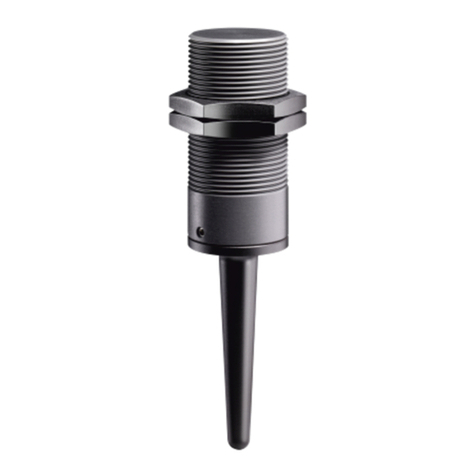
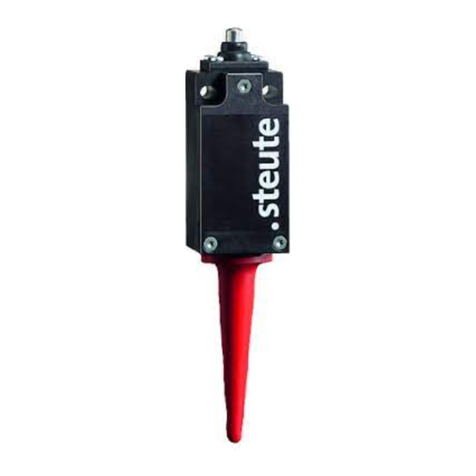
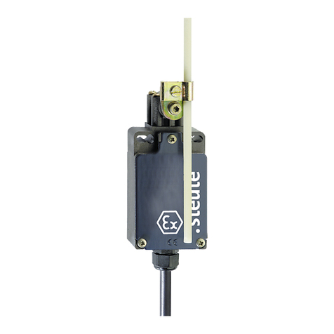
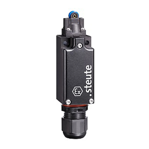
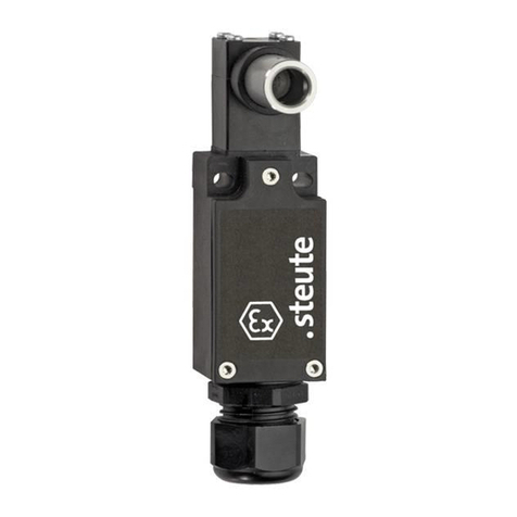
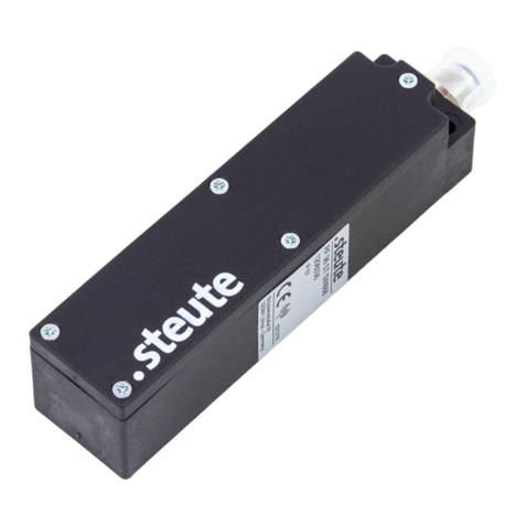
swich Ex 14 is used in safety circuits to monitor the position of mobile
safety guards to EN ISO 14119 (EN 1088) type 1 and EN 60947-5-1.
Ex 14: A depending on the variant.
Special conditions / »X« marking
- Position the device protected from shock loads.
- The device's connection cables must have a fixed installation and be
set up in a manner that protects them from mechanical damages.
- If the connection is in an explosive area, the connection cable has to
be connected in an enclosure which complies with the requirements
of an approved ignition protection degree according to EN 60079-0,
par. 1.
- The capacity of the guide bush and of the operating plunger is 4,5 ±
0,5 pF. To use the device in gas group IIC, there must be a 4 mm dis-
tance between the guide bush and surrounding metal parts.
Installation / Mounting / Dismantling
=
DANGER
Live parts. Explosive atmosphere. Electric shock
hazard! Explosion hazard! Ignoring this message
will lead to serious injuries or death. Before com-
missioning, check device for correct installation.
Comply with national provisions.
=
DANGER
Live parts. Explosive atmosphere. Electric shock
hazard! Risk of burns! Ignoring this message will
lead to serious injuries or death. Connecting and
disconnecting only to be performed by qualified and
authorised personnel. Connecting and disconnect-
ing only in non-explosive atmospheres.
Mount the device on an even surface. Any mounting position is pos-
sible. Ensure that the device cannot be moved from its position. Ensure
this in case of failure, too. For protection against unauthorized ma-
nipulation, use e.g. one way safety screws. These are optionally avail-
able. When mounting the device, observe the requirements of EN ISO
14119, especially paragraphs 5.2 and 5.3! Observe the instructions in
the standards EN ISO 12100 and EN ISO 14120.
Application and Operation
- Use device only within the permitted electrical load limits (see tech-
nical data).
- For short-circuit protection use fuse size 6 A (gG/gN).
- Use device only within the permitted ambient temperature range (see
product label and technical data)
Destination and Use
=
DANGER
Misuse and explosive environment. Explosion haz-
ard! Risk of burns! Ignoring this message will lead
to serious injuries or death. Not for use in category
1/zone 0 or zone 20. Only for use in permitted cat-
egories/zones. Use device only in accordance with
the operating conditions defined in the mounting
and wiring instructions. Use device only in ac-
cordance with the intended purpose defined in the
mounting and wiring instructions.
Bei rauen Betriebsbedingungen regelmäßig wie folgt warten:
- Betätiger auf Leichtgängigkeit prüfen.
- Schmutzreste entfernen.
- Leitungseinführung und -anschlüsse prüfen.
Entsorgung
- Nationale, lokale und gesetzliche Bestimmungen zur Entsorgung
beachten.
- Materialien getrennt dem Recycling zuführen.
Hinweise
Das Gerät nicht als mechanischen Anschlag verwenden. Umbauten
und Veränderungen am Gerät, die den Explosionsschutz beeinträchti-
gen, sind nicht gestattet. Für das Errichten von elektrischen Betriebs-
mitteln in explosionsgefährdeten Bereichen gilt die EN 60079-14. Zu
beachten sind zudem die ATEX-Prüfbescheinigung und die darin ent-
haltenen besonderen Bedingungen. Das Gerät wurde entwickelt, um
als Teil einer Anlage oder Maschine sicherheitsgerichtete Funktionen
zu übernehmen. Ein komplettes sicherheitsgerichtetes System enthält
in der Regel Sensoren, Auswerteeinheiten, Meldegeräte und Konzepte
für sichere Abschaltungen. Für die Verschaltung des Geräts in das Ge-
samtsystem muss die in der Risikoanalyse festgelegte Steuerungska-
tegorie durchgehend eingehalten werden. Hierzu ist auch eine Validie-
rung nach DIN EN ISO 13849-2 bzw. nach DIN EN 62061 erforderlich.
Desweiteren kann der Performance-Level nach DIN EN ISO 13849-1
bzw. SIL-CL-Level nach DIN EN 62061 durch Verkettung von mehre-
ren Sicherheitsbauteilen und anderen sicherheitsgerichteten Gerä-
ten, z.B. Reihenschaltung von Sensoren, niedriger ausfallen als die
Einzellevel. Es liegt im Verantwortungsbereich des Herstellers einer
Anlage oder Maschine, die korrekte Gesamtfunktion sicherzustellen.
Technische Änderungen vorbehalten. steute übernimmt keine Haftung
für Empfehlungen, die durch diese Beschreibung gegeben oder impli-
ziert werden. Aufgrund dieser Beschreibung können keine neuen, über
die allgemeinen steute-Lieferbedingungen hinausgehenden, Garan-
tie-, Gewährleistungs- oder Haftungsansprüche abgeleitet werden.
English


