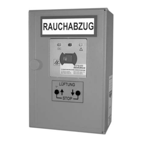
STG-BEIKIRCH MZ2 DGM Manual

Technical information
and operating instruction
Technische Information
und Bedienungsanleitung
Diese Bedienungsanleitung für späteren Gebrauch bzw. Wartung aufbewahren. Please keep these operating instruction for future reference and maintance.
Änderungen dienen dem technischen Fortschritt und bleiben vorbehalten. Abbildungen unverbindlich. Subject to technical modifications. Diagram is not binding.
Version: 2 valid from: 07.10.2009
Pressurized gas module MZ2 DGM
For connection of pressurized gas generators 24 V DC
Range
This component of the MZ2 modular
central control unit serves as an actuator
module with a monitoring function, for the
control of an actuator circuit.
Pyrotechnic compressed gas generators
with an internal resistance of 1.0 ohms to
1.6 ohms are authorised as actuators.
For operation a motor circuit of the MZ2
MM2x8A motor module is required.
With slider switches installed for the
functions:
• live: (compressed gas generator
switched on and active)
• secured: (compressed gas generator
switched off and inactive, e.g. for
maintenance tasks).
Special units
• connection option for pyrotechnic
compressed gas generator
• cascadable with further MZ2 DGM
modules
• for connection of pressurized gas
generators, max. 8 pieces
• with LED display to signal operating
states and faults
• line monitoring of the connected
pressurized gas generators
• snap-on fitting onto 35 mm mounting rail
Ausgabe: 2 Gültig ab: 07.10.2009
Datei:
Ti_MZ2_DGM_dt_engl.indd
Art.Nr. 24999654
Druckgasmodul MZ2 DGM
Zum Anschluss von 24 V DC Druckgasgeneratoren
Einsatzbereiche
Diese Komponente der Modulzentrale
MZ2 dient als Aktormodul mit
Überwachungsfunktion zur Steuerung von
einem Aktorkreis.
Als Aktor sind pyrotechnische Druck-
Gaserzeuger mit einem Innenwiderstand
von 1,0 Ohm bis 1,6 Ohm zugelassen.
Das Druckgasmodul MZ2 DGM kann nur
zusammen mit einen Motormodul MZ2
MM2x8A betrieben werden.
Mit eingebautem Schiebeschalter für die
Funktionen:
• Scharf: (Druckgasgenerator
eingeschaltet und aktiv)
• Gesichert: (Druckgasgenerator
ausgeschaltet und inaktiv, z. B. für
Wartungsarbeiten).
Besonderheiten
• Anschlussmöglichkeit für
pyrotechnische Druckgaserzeuger
• kaskadierbar mit weiteren Druckgas-
modulen
• maximal 8 Druckgasgeneratoren pro
Druckgasmodul anschließbar
• mit LED-Anzeige zum Signalisieren der
Betriebszustände und Fehler
• Leitungsüberwachung der
angeschlossenen Druckgasgeneratoren
• Schnapp-Montage auf Montageschiene
mit Busklemmen
DGM

2
Safety instructions
Please observe the following safety instructions which
are emphasized by special symbols.
Caution: Danger to persons due to electricity.
Warning: Non-observance leads to destruction.
Danger to material due to incorrect handling
Attention: Danger to persons due to risks arising from
the operation of the equipment. Danger of crushing/trap-
ping.
INFO
Warning 230 V AC: Dangerous voltage. Can cause death, serious injury or
considerable material damage. Disconnect the equipment from the power supply
at all poles before opening, assembling or carrying out any structural alterations.
Observe VDE 0100 for 230 V power connection.
Attention: Pressurized gas generators are pyrotechnic generators of
pressurized gas.
BAM-classification
Class T1 (does not require a permit according to Exception Regulations §4, Sect.
3.2.1 Explosives Provisions, Exception No. S 76 GGVS, but is only to be used by
trained personnel) 1.4.S, UN 0432, ADR No. 39, charge weight 0.15 g. Never connect
the high-pressure gas generator to the power source if the high-pressure gas
generator is not screwed into its working position. Never place the high-pressure
gas generator on heat sources (risk of activation and shattering). Do not use force to
open (e.g. by sawing) - risk of activation. Do not smoke. When installing or removing
always disconnect the power source first.
Operating instructions: for professional assembly, installation and appropriate
maintenance by trained, qualified and safety-conscious electricians and/or skilled
staff with knowledge of electrical equipment installation.
Read and observe the information contained in these operating instructions and
respect the order of procedure stated therein. Please keep these operating
instructions for future reference and maintenance. Reliable operation and the
prevention of damage and risks are only granted if the equipment is assembled
carefully and the settings are carried out according to these instructions and to the
operating instructions of the drives. Please observe the exact terminal assignment,
the minimum and maximum power ratings (see technical data) and the installation
instructions.
It would be beyond the scope of these safety instructions to list all the valide
regulations and guidelines. Always make sure that your system corresponds to the
valid regulations. Pay particular attention to: the aperture cross-section of the window,
the opening time and opening speed, the temperature resistance of the cables and
equipment, cross-sections of the cables in relation to the cable lengths and power
consumption. Required mounting material is to be adapted to the frame and the
corresponding load and is to be completed, if necessary. Any supplied mounting
material is only part of the required amount.
Sicherheitshinweise
Sicherheitshinweise, die Sie unbedingt beachten müssen,
werden durch besondere Zeichen hervorgehoben.
Vorsicht: Gefahr für Personen durch elektrischen Strom.
Achtung: Nichtbeachtung führt zur Zerstörung
Gefährdung für Material durch falsche Handhabung.
Warnung: Gefährdung für Personen durch Gefahren
aus dem Gerätebetrieb. Quetsch- und Klemmgefahr.
INFO
Warnung 230 V AC: Gefährliche Spannung. Kann Tod, schwere Körperverletzung
oder erheblichen Sachschaden verursachen. Trennen Sie das Gerät allpolig von der
Versorgungsspannung bevor Sie es öffnen, montieren oder den Aufbau verändern.
VDE 0100 für 230 V Netzanschluss beachten.
Achtung: Druckgasgeneratoren sind pyrotechnische Druckgaserzeuger.
BAM-Klassifizierung
Klasse T1 (nicht Erlaubnisscheinpflichtig gem. Ausnahmeregelung §4, Abs. 3.2.1
Sprengstoffverordnung, Ausnahme Nr. S 76 GGVS, aber nur von geschulten Personal
zu benutzen) 1.4.S, UN 0432, ADR Ziff. 39, Satzgewicht 0,15 g Druckgasgeneratoren
nie mit der Spannungsquelle verbinden, wenn der Druckgasgenerator nicht an
seinem Arbeitsplatz eingeschraubt ist. Den Druckgasgenerator nie auf Wärmequellen
legen (Zündgefahr und Splitter). Nicht gewaltsam öffnen (z.B. sägen) - Zündgefahr.
Nicht rauchen. Beim Ein- oder Ausbau immer erst Spannungsquelle abklemmen.
Bedienungsanleitung für die fachgerechte Montage, Installation und angemessene
Wartung durch den geschulten, sachkundigen und sicherheitsbewussten Elektro-
Installateur und / oder Fachpersonal mit Kenntnissen der elektrischen Geräte-
installation. Lesen und Beachten Sie die Angaben in dieser Bedienungsanleitung und
halten Sie die vorgegebene Reihenfolge ein. Diese Bedienungsanleitung für späteren
Gebrauch / Wartung aufbewahren. Ein zuverlässiger Betrieb und ein Vermeiden von
Schäden und Gefahren ist nur bei sorgfältiger Montage und Einstellung nach dieser
Anleitung gegeben. Bitte beachten Sie genau die Anschlussbelegung, die minimalen
und maximalen Leistungsdaten (siehe technischen Daten) und die Installations-
hinweise.
Es würde den Rahmen dieser Bedienungsanleitung sprengen, alle gültigen
Bestimmungen und Richtlinien aufzulisten. Prüfen Sie immer, ob Ihre Anlage den
gültigen Bestimmungen entspricht. Besondere Beachtung finden dabei: Öffnungs-
querschnitt des Fensters, Öffnungszeit und Öffnungsgeschwindigkeit, Temperatur-
beständigkeit von Kabel und Geräten. Benötigtes Befestigungsmaterial ist mit dem
Baukörper und der entsprechenden Belastung abzustimmen und, wenn nötig, zu
ergänzen. Ein eventuell mitgeliefertes Befestigungsmaterial entspricht nur einem Teil
der Erfordernisse.

3
Safety instructions
Routing of cables and electrical connections only to be done by a qualified
electrician. Adhere to the type of cables, cable lengths and cross-sections as stated
in the technical information.
Power supply leads 230 V AC to be fused separately by the customer. Keep power
supply leads sheathed until the mains terminal. All low voltage cables (24 V DC) to be
installed separately from high voltage cables. Never use a star-shaped wiring layout,
but always wire up from SHE operating station to SHE operating station, from
pressurized gas generator. To pressurized gas generator, and from automatic
detector to automatic detector. DIN and VDE regulations to be observed for the
installation: VDE 0100 Setting up of high voltage installations up to 1000 V. VDE 0815
Installation cables and wires. VDE 0833 Alarm systems for fire, break-in and burglary.
Cable types to be agreed with local inspection authorities, power utilities, fire
protection authority and the professional associations. Flexible cables must not be
plastered in. Provide tension relief for freely suspended cables. The cables must be
installed in such a way that they cannot be sheared off, twisted or bent off during
operation. Junction boxes must be accessible for maintenance work.
Feed all lines through the holes provided for this purpose and connect up in
accordance with the connection diagram. The „secured / active“ function switch must
be placed in the „secured“ position before any work on the central control unit.Before
connecting up the high-pressure gas generator wiring this must be checked for elec-
trical continuity using an ohmmeter. The internal resistance should be 1.0 - 1.6 ohms
per high-pressure gas generator. No activation up to 0.18 A! The lines are connected
up and the mains is then connected to the main distribution system (fuses are in
particular to be identified). The cable types could only be recommendations.
Cable types to be agreed with local inspection authorities, power utilities, fire
protection authority and the professional associations.
The supply voltage and the batteries are to be disconnected at
all poles before maintenance work or structural alterations. The
system must be protected against unintentional re-starting. Electrical controls
must be voltage free before extension modules are taken off or added
(disconnect mains voltage and batteries).
After installation and any changes to the system check all functions by a trial
run.
Attention: The control must only be operated with drives made by the
same manufacturer. No liability will be accepted and no guarantee
nor service is granted if products of outside manufacturers are used. Assembly and
installation must be carried out properly, according to the information of the operating
instructions paying particular attention to safety aspects. If spare parts, dismantled
parts or extension components are required or desired, only use original spare parts.
Manufacturer’s declaration: The equipment has been manufactured and tested
according to the European regulations. A corresponding manufacturer’s declaration
has been submitted. You may only operate the system if a declaration of conformity
exists for the entire system.
Sicherheitshinweise
Leitungsverlegung und elektrischer Anschluss nur durch zugelassene Elektrofirma.
Die Kabelarten, -längen und -querschnitte gemäß den technischen Angaben
ausführen.
Netzzuleitungen 230 V AC separat bauseits absichern. Netzzuleitungen bis an die
Netzklemme ummantelt lassen. Alle Kleinspannungsleitungen (24 V DC) getrennt von
Starkstromleitungen verlegen. Bei der Leitungsverlegung nie sternförmig vorgehen,
sondern immer von RWA-Bedienstelle zu RWA-Bedienstelle, von Druckgasgenerator
zu Druckgasgenerator und von autom. Melder zu autom. Melder.
Bei der Installation DIN- und VDE-Vorschriften beachten, VDE 0100 Errichten von
Starkstromanlagen bis 1000 V, VDE 0815 Installationskabel und -leitungen, VDE 0833
Gefahrenmeldeanlagen für Brand, Einbruch und Überfall.
Kabeltypen ggf. mit den örtlichen Abnahmebehörden, Energieversorgungs-
unternehmen, Brandschutzbehörden oder Berufsgenossenschaften festlegen.
Flexible Leitungen dürfen nicht eingeputzt werden. Frei hängende Leitungen mit
Zugentlastung versehen. Die Leitungen müssen so verlegt sein, dass sie im Betrieb
weder abgeschert, verdreht noch abgeknickt werden. Abzweigdosen müssen für
Wartungsarbeiten zugänglich sein.
Alle Leitungen durch die dafür vorgesehenen Bohrungen einführen und gemäß
Anschlussplan einklemmen. Der Funktionsschalter “gesichert <-> scharf” muss vor
allen Arbeiten an der Zentrale auf “gesichert” gestellt werden. Vor dem Anklemmen
der Druckgasgeneratoren-Leitungen werden diese mittels eines Widerstands-
messgerätes auf “Durchgang” gemessen. Der Innenwiderstand sollte 1,0 - 1,6 Ohm
pro Druckgasgenerator sein. Keine Zündung bis 0,18 A! Die Leitungen werden
angeklemmt, anschließend wird das Netz an der Hauptverteilung eingeschaltet
(Sicherungen sind besonders zu kennzeichnen). Die Leitungstypen können nur
Empfehlungen sein. Sie müssen auf jeden Fall mit der Bauleitung, mit den örtlichen
Abnahmebehörden, Energieversorgungs-unternehmen, Brandschutzbehörden oder
der Berufsgenossen-schaft abgestimmt werden.
Vor jeder Wartungsarbeit oder Veränderung des Aufbaus sind
die Netzspannung und Akkus allpolig abzuklemmen. Gegen
unbeabsichtigtes Wiedereinschalten ist die Anlage abzusichern. Elektrische
Steuerungen müssen stromlos sein, bevor Sie Teile entnehmen oder dazusetzen
(Netzspannung und Akkus abklemmen).
Nach der Installation und jeder Veränderung der Anlage alle Funktionen durch
Probelauf überprüfen.
Achtung: Steuerungen und externe Geräte vom gleichen Hersteller
auswählen. Bei Verwendung von Fremdfabrikaten können Abweichungen
der Leistungsdaten auftreten. Werden Ersatzteile, Ausbauteile oder Erweiterungen
benötigt bzw. gewünscht ausschließlich Originalersatzteile verwenden.
Herstellererklärung: Die Geräte sind gemäß der europäischen Richtlinien geprüft und
hergestellt. Eine entsprechende Herstellererklärung liegt vor. Sie dürfen die Geräte
nur dann betreiben, wenn für das Gesamtsystem eine Konformitätserklärung vorliegt.

4
Terminal assignment
Numbering the connection terminals
follows the same principle for all MZ2
modules (exception power supply unit
NM16A).
Module-view:
Starts at top left. The numbering is
continued at each deeper level, starting
at the left.
Numbering of the bottom terminal row is
continued as per the procedure described
above.
Connections
Please see the wiring and terminal plan for
the position of the terminals and the wiring
with the MZ2 modules and actuators.
Warning: The module must
never be fitted on the top hat rail when the
supply is switched on. This can lead to
the destruction of the module and to the
triggering of the actuators connected.
Terminals 1+2: Output for actuator circuit
(compressed gas generator)
Terminal 3: Output for PE protective
conductor for compressed gas generator
Terminal 10: Input for PE protective
conductor
Terminal 11: Output for PE protective
conductor (onward transmission to the
next DGM)
Terminal 12: Output for PE protective
conductor (onward transmission to the
next DGM)
Terminal 4: Input for trigger for pyrotechnic
compressed gas generator (-)
Terminal 5: Input for trigger for pyrotechnic
compressed gas generator (+)
Terminal 6: Monitoring circuit for DGM
MM2x8A
Terminal 13: Input for +24 V DC
(optional operating voltage)
Terminal 14: Not occupied
Terminal 15: Input for -24 V DC (optional
operating voltage)
top terminal row
(as a rule the terminal board for the fitter)
bottom terminal row
(usually wired up in the factory, or not occupied)
max. allowable
8 pieces
clamp 3
clamp 2
clamp 1
Output motor module MM2x8A
Klemmbelegung
Die Nummerierung der Anschluss-
klemmen erfolgt bei allen MZ2-Modulen
nach dem gleichen Prinzip (Ausnahme:
Netzmodul NM16A).
Modul-Draufsicht:
Begonnen wird links oben.
Jede Ebene tiefer wird die Nummerierung
links beginnend fortgeführt.
Die Nummerierung der unteren
Klemmreihe wird nach dem oben
beschriebenen Verfahren fortgeführt.
Anschlüsse
Die Lage der Klemmen und die
Verdrahtung mit dem MZ2-Netzteil und
den Aktoren entnehmen Sie bitte dem
Klemmplan.
Achtung: Das Modul darf
niemals bei eingeschalteter Versorgung
auf die Hutschiene montiert werden. Dies
kann zur Zerstörung des Moduls und zur
Auslösung der angeschlossenen Aktoren
führen.
Klemme 1 + 2: Ausgang Aktorkreis
(Druckgaserzeuger)
Klemme 3: Ausgang Schutzleiter PE für
Druckgaserzeuger
Klemme 10: Eingang Schutzleiter PE
Klemme 11: Ausgang Schutzleiter PE
(Weiterleitung zum nächsten DGM)
Klemme 12: Ausgang Schutzleiter PE
(Weiterleitung zum nächsten DGM)
Klemme 4: Eingang Auslösung
Pyrotechnischer Druckgaserzeuger (-)
Klemme 5: Eingang Auslösung
Pyrotechnischer Druckgaserzeuger (+)
Klemme 6: Überwachungsleitung vom
DGM MM2x8A
Klemme 13: Eingang +24 V DC
(optionale Betriebsspannung)
Klemme 14: nicht belegt
Klemme 15: Eingang -24 V DC
(optionale Betriebsspannung)
obere Klemmreihe
(i.d.R. die Anschlussleiste für den Monteur)
untere Klemmreihe
(i.d.R. werksseitig vorverdrahtet oder nicht belegt)
max. 8 Stück
Klemme 3
Klemme 2
Klemme 1
Ausgang vom Motor Modul MM2x8A
obere Klemmreihe
(i.d.R. die Anschlussleiste für den Monteur)
top terminal row
(as a rule the terminal board for the fitter)
untere Klemmreihe
(i.d.R. werksseitig vorverdrahtet oder nicht belegt)
bottom terminal row
(usually wired up in the factory, or not occupied)
1 2 3
4 5 6
DGM
10 11 12
13 14 15
1 2 3
4 5 6
10 11 12
13 14 15
7 8 9
7 8 9
aus/off
an/on

5
Connections
Terminal 7: Output for trigger for
pyrotechnic compressed gas generator (-)
(onward transmission to the next DGM or
termination circuit with diodes)
Terminal 8: Output for trigger for
pyrotechnic compressed gas generator
(+) (onward transmission to the next DGM
or termination circuit with diodes)
Terminal 9: Monitoring circuit for DGM
(onward transmission to the next DGM or
termination circuit with diodes)
Control-& indicator panels
LED
Colour: yellow
Function: malfunction*
LED lights up, in the event that:
- DG switch “DG off” is switched off
- fault occurs in the cable monitoring
- compressed gas generator is activated
after the trigger.
* Each malfunction message from the
DGM compressed gas module is
transmitted onwards to the respective
assigned MM2x8A motor module. This
malfunction is detected in the motor
module as cable monitoring and is
signalled as a fault.
LED
Colour: red
Function: SHE trigger
The LED lights up, if a trigger has been
activated.
LED
ein/on
Colour: green
Function: actuator circuit is switched on
“DG on”
LED lights up: DG switch in “DG on”
position (compressed gas generator is
live).
LED
aus/off
Colour: yellow
Function: actuator circuit is switched off
“DG off”
LED lights up:
DG switch in “DG off” position
(compressed gas generator is secured).
Switch:
DG ON (1)
DG OFF (A)
Anschlüsse
Klemme 7: Ausgang Auslösung
Pyrotechnische Druckgaserzeuger (-)
(Weiterleitung zum nächsten DGM oder
Abschluss Schaltung mit Dioden)
Klemme 8: Ausgang Auslösung
Pyrotechnische Druckgaserzeuger (+)
(Weiterleitung zum nächsten DGM oder
Abschluss Schaltung mit Dioden)
Klemme 9: Überwachungsleitung DGM
(Weiterleitung zum nächsten DGM oder
Abschluss Schaltung mit Dioden)
Bedien- & Anzeigeelemente
LED
Farbe: Gelb.
Funktion: Störung*.
LED leuchtet, bei:
- DG-Schalter “DG aus” ist ausgeschaltet.
- Fehler in der Leitungsüberwachung.
- Druckgaserzeuger ist nach der
Auslösung ausgelöst.
* Jede Störungsmeldung vom Druckgas-
modul DGM wird an das jeweilige
zugeordnete Motormodul MM2x8A
weitergeleitet. Diese Störung wird im
Motormodul als Leitungsüberwachung
erkannt und als Fehler signalisiert.
LED
Farbe: Rot.
Funktion: RWA Auslösung.
Die LED leuchtet, wenn eine Auslösung
aktiviert wurde.
LED
ein/on
Farbe: Grün.
Funktion: Aktorkreis ist eingeschaltet,
“DG an”.
LED leuchtet: DG-Schalter auf Position
“DG an” (Druckgaserzeuger ist scharf).
LED
aus/off
Farbe: Gelb.
Funktion: Aktorkreis ist ausgeschaltet,
“DG aus”.
LED leuchtet: DG-Schalter auf Position
“DG aus” (Druckgaserzeuger ist
gesichert).
Schalter:
DG EIN (1)
DG AUS (A)
DGM
!
ein/on
aus/off
1A
Schalter:
DG EIN (1)
DG AUS (A)
!
ein/on
aus/off
Switch:
DG on (1)
DG off (A)

6
Control-& indicator panels
“DG” slider switch
For switching the actuator circuit on and
off.
Function of the slider switch:
Position 1: “DG ON, i.e. live” (compressed
gas generator switched on and active).
Position A: “DG OFF, i.e. secured”
(compressed gas generator switched off
and inactive, e.g. for maintenance tasks).
Functions for MZ2
The DGM compressed gas module and
MM2x8A motor module provide the
following functions, which can be
configured individually by means of the PC
software (the exception being the DGM).
The DGM can only be controlled in
conjunction with a motor module. This
module on its own is not included in the
MZ2 PC software.
The faults detected in the self-tests and
test functions of the motor module are
signalled via the flow LED channel A or B
and transferred to the MCU module and
to the GM modules (see also the table of
motor module flash codes).
Operating state
Operationally ready
The DG slider switch is located in the
position “DG ON” and the LED display
“DG ON” is lit up. This signals that the
actuator circuit is switched on. The cables
of the pyrotechnic compressed gas
generator are monitored for cable
fractures.
Manual trigger in the event of fire/
combustion/alarm
Smoke extraction / compressed gas
generators triggered
Press red ON button in an SHE
operating station compressed gas
generators are triggered. The smoke and
heat extractors open via the ignition of
the compressed gas generators and by
broaching the CO2 or N2 pressurised gas
media installed in the smoke and heat
extractors. Red LED display –SHE
triggered - lights up in all SHE operating
stations, and also in the assigned MZ2
group modules and MZ2 compressed gas
modules.
Option
DG ON DG OFF
Switch:
DG ON (1)
DG OFF (A)
Bedien- & Anzeigeelemente
Schiebeschalter “DG”
Zum Ein- und Ausschalten des
Aktorkreises.
Funktion des Schiebeschalters:
Stellung 1: “DG EIN bzw. scharf” Druck-
gasgenerator eingeschaltet und aktiv.
Stellung A: “DG AUS bzw. Gesichert”
Druckgasgenerator ausgeschaltet und
inaktiv, z. B. für Wartungsarbeiten.
Funktionen für die MZ2
Das Druckgasmodul DGM und das
Motormodul MM2x8A stellen folgende
Funktionen bereit, die im Einzelnen durch
die PC-Software konfiguriert (Ausnahme
DGM) werden kann. Das DGM kann nur
in Verbindung mit einem Motormodul
angesteuert werden. Dieses Modul selber
wird nicht von der MZ2 PC-Software
eingebunden.
Die bei den Selbsttests und Testfunktionen
des Motormoduls erkannten Fehler
werden über die Ströungs-LED Kanal A
oder B signalisiert und an das MCU-Modul
und an die GM-Module übertragen (siehe
auch die Tabelle Blinkcodes Motormodul).
Betriebszustand
Betriebsbereit
Der Schiebeschalter DG befindet sich
in der Stellung “DG EIN” und die LED
Anzeige “DG EIN” leuchtet. Dieses signa-
lisiert dass der Aktorkreis eingeschaltet
ist. Die Leitungen der pyrotechnischen
Druckgaserzeuger werden auf Kabelbruch
überwacht.
Manuelle Auslösung bei Feuer/
Brand/Alarm
Rauchabzug / Druckgasgeneratoren
ausgelöst
Rote AUF-Taste in einer
RWA-Bedienstelle drücken Druckgas-
generatoren werden ausgelöst. Die
Rauch- und Wärmeabzüge öffnen sich
über die Zündung der Druckgas-
generatoren und durch Anstich der in den
Rauch-Wärmeabzüge eingebauten
Druckmedien CO2- oder N2-Gas. Rote
LED-Anzeige - RWA ausgelöst -
leuchtet in allen RWA-Bedienstellen, wie
auch in den zugeordneten MZ2 Gruppen-
modulen und MZ2 Druckgasmodulen.
Schalter:
DG EIN (1)
DG AUS (A)
Variante
DG Ein DG Aus

7
Functions for MZ2
The green LED display
OK
in the SHE
operating stations continues to be lit up.
Close smoke extractor /dome lights
After triggering has taken place the slider
switch in the MZ2 compressed gas
module must be switched to the “secured”
position. The yellow LED display
aus/
off
“DG OFF”, the red LED display “DG
trigger” and the yellow LED display
“Malfunction” light up.
The yellow LED display in the MZ2
motor module “Malfunction“ flashes
(flash code 5) in all operating stations.
Press CLOSE button in an SHE
operating station the red LED display
“SHE triggered” is extinguished in all
SHE operating stations the compressed
gas generators and also the energy
sources for the smoke and heat
extractors - CO2 or N2 bottles must be
renewed and the dome lights must be
closed correctly. In the central control
system the slider switch is then
switched to the “live” position. In the
MZ2 compressed gas module the green
LED display
ein/on
lights up “DG ON”, and
the yellow LED display “DG
malfunction” is extinguished. Only now
is the yellow LED display
“Malfunction“ extinguished and the green
LED display
OK
lights up in the MZ2
motor module.
Note: No RESET of the connected and
triggered automatic detectors occurs!
Automatic trigger in the event of fire/
combustion/alarm
Only if automatic detectors are connected.
Smoke extraction / compressed gas
generators triggered
Smoke reaches the automatic detectors
compressed gas generators are
triggered. The smoke and heat extractors
open via the ignition of the compressed
gas generators and by broaching the CO2
or N2 pressurised gas media installed in
the smoke and heat extractors.
red LED display SHE triggered -
lights up in all SHE operating stations, and
also in the assigned MZ2 group modules
and MZ2 compressed gas modules, the
green LED display
OK
is extinguished in
the SHE operating stations.
Die grüne LED
OK
in den
RWA-Bedienstellen leuchtet weiter.
Rauchabzug / Lichtkuppeln schließen
Nach erfolgter Auslösung muss der Schie-
beschalter im MZ2 Druckgasmodul in
Stellung “gesichert” geschaltet werden.
Die gelbe LED Anzeige
aus/off
“DG AUS”,
die rote LED Anzeige “Auslösung DG”
und die gelbe LED Anzeige “Störung”
leuchten.
Die gelbe LED Anzeige im MZ2-Motor-
modul “Störung” blinkt (Blinkcode 5)
in allen Bedienstellen.
ZU-Taste in einer RWA-Bedienstelle
drücken die rote LED-Anzeige - “RWA
ausgelöst” - erlischt in allen RWA-
Bedienstellen die Druckgasgeneratoren
sowie die Energieträger der Rauch-
Wärmeabzüge - CO2- oder N2-Flaschen
müssen erneuert und die Lichtkuppeln
müssen fachgerecht geschlossen werden.
Anschließend wird der Schiebeschalter in
der Zentrale in Stellung “scharf”
geschaltet. Im MZ2-Druckgasmodul
leucht die grüne LED Anzeige
ein/on
“DG
ein” und die gelbe LED Anzeige
“Störung DG” erlischt.
Jetzt erst erlischt die gelbe LED An-
zeige “Störung” und die grüne LED
Anzeige
OK
leuchtet im MZ2-Motormodul
auf.
Hinweis: es erfolgt kein Zurücksetzen
(RESET) der angeschlossenen und
ausgelösten automatischen Melder!
Automatische Auslösung bei Feuer/
Brand/Alarm
Nur wenn automatische Melder
angeschlossen sind.
Rauchabzug / Druckgasgeneratoren
ausgelöst
Rauch erreicht die automatischen Melder
Druckgasgeneratoren werden
ausgelöst. Die Rauch-Wärmeabzüge
öffnen sich über die Zündung der Druck-
gasgeneratoren und durch Anstich der in
den Rauch-Wärmeabzüge eingebauten
Druckmedien CO2- oder N2-Gas. Rote
LED-Anzeige - RWA ausgelöst -
leuchtet in allen RWA-Bedienstellen, wie
auch in den zugeordneten MZ2 Gruppen-
modulen und MZ2 Druckgasmodulen, die
grüne LED Anzeige
OK
erlischt in den
RWA-Bedienstellen.
Funktionen für die MZ2

8
Reset of the “SHE trigger” and the
automatic detectors
Remove smoke from automatic detectors
(by blowing out or replacement, in the
event of severe contamination).
Close smoke extractor /dome lights
After triggering has taken place the slider
switch in the central control system must
be switched to the “secured” position.
The yellow LED display
aus/off
“DG OFF”,
the red LED display “DG trigger” and
the yellow LED display ““Malfunction”
light up.
The yellow LED display in the MZ2
motor module “Malfunction“ flashes
(flash code 4) in all SHE operating
stations. Press SHE RESET button in the
central control unit (MZ2 group module).
The red display in the automatic
detector is extinguished.
The yellow LED display in the MZ2
motor module “Malfunction“ now
flashes (flash code 5) in all SHE operating
stations.
The compressed gas generators and
also the energy sources for the smoke and
heat extractors Co2 or N2 bottles must
be renewed and the dome lights must be
closed correctly.
The slider switch is then switched in
the central control system to the “live”
position.
In the MZ2 compressed gas module
the green LED display
ein/on
lights up “DG
ON”, and the yellow LED display
“DG malfunction” is extinguished.
Only now is the yellow LED display
“Malfunction“ extinguished and the
green LED display
OK
lights up in the
MZ2 motor module.
Functions for MZ2
Zurücksetzen der “RWA Auslösung”
und der automatischen Melder
Automatische Melder von Rauch befreien
(durch Ausblasen bzw. bei starker
Verschmutzung ersetzen).
Rauchabzug / Lichtkuppeln schließen
Nach erfolgter Auslösung muss der
Schiebeschalter in der Zentrale in Stellung
“gesichert” geschaltet werden.
Die gelbe LED Anzeige
aus/off
“DG aus”,
die rote LED Anzeige ”Auslösung DG”
und die gelbe LED Anzeige “Störung”
leuchten.
Die gelbe LED Anzeige im MZ2-Motor-
modul “Störung” blinkt (Blinkcode 4)
in allen RWA-Bedienstellen.
Taste RWA-Reset in der Steuerzentrale
(MZ2 Gruppenmodul) drücken.
Die rote Anzeige im automatischen
Melder erlischt.
Die gelbe LED Anzeige im MZ2-Motor-
modul “Störung” blinkt jetzt (Blink-
code 5) in allen RWA-Bedienstellen.
Die Druckgasgeneratoren sowie die
Energieträger der Rauch-Wärmeabzüge -
CO2- oder N2-Flaschen - müssen erneuert
und die Lichtkuppeln müssen fachgerecht
geschlossen werden.
Anschließend wird der Schiebe-
schalter in der Zentrale in Stellung “scharf”
geschaltet. Im MZ2-Druckgasmodul
leuchtet die grüne LED Anzeige
ein/on
“DG ein” und die gelbe LED Anzeige
“Störung DG” erlischt.
Erst jetzt erlischt die gelbe LED Anzeige
“Störung” und die grüne LED Anzeige
OK
leuchtet im MZ2-Motormodul.
Funktionen für die MZ2

9
Possible connections
Montoring diodes one pressurized gas module DGM several pressurized gas modules DGM
max. 8 pressurized gas generators per line Monitoring diodes:
In the event of
cascading several DG
modules, insert the
monitoring diodes in
the last module.
motor circuit A motor circuit B
Pressurized gas
generator
Montoring diodes
Diode switching
Pressurized gas
generator Pressurized gas
generator
control
output OPEN
contro
output OPEN
output actor
output actor
protection earth
input actor
transmission actor
transmission control
input actor
control
transmission actor
protection earth
+ 24 V / in optional
- GND / in optional
protection earth
protection earth
output actor
output actor
protection earth
input actor
transmission actor
transmission control
input actor
control
transmission actor
protection earth
+ 24 V / in optional
- GND / in optional
protection earth
protection earth
max. 6 pressurized gas module DGM cascadable
Pressurized gas
generator
Anschlussmöglichkeiten
Überwachungsdioden ein Druckgasmodul DGM mehrere Druckgasmodule DGM
Diodenpolung
Druckgasgenerator
Druckgasgenerator
max. 8 Druckgasgeneratoren pro Linie
Druckgasgenerator
Überwachungsdioden
Überwachungsdioden
bei Kaskadierung
mehrerer DG-Module,
Überwachungsdioden
im letzten Modul
einsetzen.
Motorkreis A Motorkreis B
Überwachung
Ausg. Auf
Überwachung
Ausg. Auf
Ausgang Aktor
Ausgang Aktor
Überwachung
Schutzleiter
Eingang Aktor
Eingang Aktor
Weiterleitung Aktor
Weiterleitung Aktor
Weiterleitung Überwachung
PE Schutzleiter
PE Schutzleiter
PE Schutzleiter
+ 24 V / in optional
- GND / in optional
Ausgang Aktor
Ausgang Aktor
Überwachung
Schutzleiter
Eingang Aktor
Eingang Aktor
Weiterleitung Aktor
Weiterleitung Aktor
Weiterleitung Überwachung
PE Schutzleiter
PE Schutzleiter
PE Schutzleiter
+ 24 V / in optional
- GND / in optional
max. 6 Druckgasmodule DGM kaskadierbar
Druckgasgenerator
1 2 3 4 5 6 7 8
MZ2 MM2x8A
9 10 11 12 13 14 15 16
+ 24 V / in
+ 24 V / in
1 2 3 4 5 6 7 8 9
MZ2 DGM
10 11 12 13 14 15
1 2 3 4 5 6 7 8 9
MZ2 DGM
10 11 12 13 14 15
7 8 9
+ 24 V / out
- GND / in
- GND / out
+ 24 V / out
- GND / in
- GND / out
Motor A1
Motor A2
Motor A1
Motor A2

10
Example of assembly
Smoke vent
e.g. domelight 170°
with thermic electrical control (pressurized gas generator).
This is a construction recommendation.
Please observe the particular regulations, i.e.
several SHE manual call points and smoke
detectors could be required.
Before assembly, installation and any
modification switch the slider switch to
“secured”.
Before attachment of the compressed gas
generator cables these are measured for
“continuity” using an ohmmeter. The internal
resistance should be 1.0 to 1.6 ohms per
compressed gas generator. No ignition up to
0.18 amp!
Releasing device:
pressurized gas
generator with CO2
bottle
pneumatic lift cylinder
Smoke vent
domelight
Pipeline
steel 6 x 0.7 mm from releasing
device to pneumatic lift cylinder
SHE manual call point, max. 10 pieces
Connecting cable, please observe max. cable lenghts!
autom. detector
autom. detector
Connecting cable, please observe max. cable lenghts!
Montagevariante
Rauchabzugsklappen
z. B. Überschlagklappe 170°
mit thermisch-elektrischer Steuerung (DG).
Dieses ist ein Ausführungsvorschlag.
Die jeweilige Landesbauordnung ist zu beachten, d.h. evtl.
können mehrere RWA-Bedienstellen und autom. Melder
gefordert werden.
Vor der Montage, Installation und vor jeder
Änderung den Schiebeschalter auf “gesichert”
schalten.
Vor dem Anklemmen der Druckgasgeneratorenleitungen
werden diese mittels Ohmmeter auf “Durchgang”
gemessen. Der Innenwiderstand sollte 1,0 bis 1,6 Ohm
pro Druckgasgenerator sein. Keine Zündung bis 0,18 A!
Rohrleitung
Stahl 6 x 0,7 mm
von RWG-Auslöseeinrichtung zum
Pneumatikzylinder
RWA-Bedienstelle, max. 10 Stück
Anschlussleitungen, maximale Leitungslänge beachten!
autom. Melder autom. Melder
Auslöseeinrichtung:
Druckgasgenerator
mit CO2-Flasche
pneumatischer
Hubzylinder
Rauchabzugs-
klappe
Lichtkuppel
(NRWG)
Anschlussleitungen, maximale Leitungslänge beachten!
Connecting cable, please observe max. cable lenghts!
Anschlussleitungen, maximale Leitungslänge beachten!
Rohrleitung
Stahl 6 x 0,7 mm
von RWG-Auslöseeinrichtung zum
Pneumatikzylinder
Rauchabzug
Smoke heat extraction
Pipeline
steel 6 x 0.7 mm from releasing
device to pneumatic lift cylinder
RWA-Bedienstelle, max. 10 Stück
SHE manual call point, max. 10 pieces
autom. Melder
autom. detector
autom. Melder
autom. detector
Rauchabzugsklappe
Lichtkuppel
(NRWG)
Smoke vent
domelight
Auslöseeinrichtung:
Druckgasgenerator
mit CO -Flasche
2
Releasing device:
with CO bottle
2
pressurized gas generator
pneumatischer Hubzylinder
pneumatic lift cylinder
RWA Zentrale
SHE contol panel
Connecting cable, please observe max. cable lenghts!
Anschlussleitungen, maximale Leitungslänge beachten!
Connecting cable, please observe max. cable lenghts!

11
Routing of cables
1) Only pressurized gas generators with a guaranteed internal resistance of 1.0 to 1.6
ohms per pressurized gas generator may be used.
2) The terminals in the central control unit are designed for maximum wiring cross-
sections of 2.5 mm2. If larger cross-sections are used then the cross-section must be
reduced in size immediately ahead of the central control unit.
Make sure all cable types and specifications are
according to site management requirements and the appropriate
national and local codes and laws.
The stated cable cross sections must not be reduced.
They are listed for an ambient temperature of 20 °C. Increase the
cross sections for higher temperatures.
For E90 (E30), all cable cross sections must be adapted to the
manufacturer‘s specifications.
All cables to the control panel (except the mains supply lead) carry
24 V DC and must be routed separately from the mains supply
lead. When routing the cables, please observe the corresponding
VDE regulations.
Pressurized gas generators
last autom. detector with end resistor, max. 10 pieces
SHE manual call point, max.
10 pieces last SHE manual call point, max. 10 pieces
autom. detector
Control panel
Mains 230 V / 50 Hz
NYM-J 3 x 1.5 mm²,
Netz 400 V / 50 Hz
NYM-J 5 x 1,5 mm²,
provide a separately
disconnetible circuit.
Secure against unintentinal
switching-off.
Scheme of cable cross section
Installation cable NYM-J with green/yellow Quantity of pressurized gas generators
max. lengths (m)
Leitungsverlegung
1) Es dürfen nur Druckgasgeneratoren mit einem garantierten Innenwiderstand von
1,0 bis 1,6 Ohm pro Druckasgenerator zur Verwendung kommen.
2) Die Klemmstellen in der Steuerzentrale sind für maximale Leitungsquerschnitte bis
2,5 mm² ausgelegt. Werden größere Querschnitte verwendet, so ist eine Querschnitt-
reduzierung unmittelbar vor der Steuerzentrale durchzuführen.
Es sind die gültigen Vorgaben bzgl. einer Verkabelung
mit Funktionserhalt 30 Min. oder 90 Min. einzuhalten.
Abweichungen hierzu sind in jedem Fall mit der Bauleitung, mit den
örtlichen Abnahmebehörden, Energieversorgungsunternehmen,
Brandschutzbehörden oder der Berufsgenossenschaft
abzustimmen.
Die angegebenen Leitungsquerschnitte dürfen nicht verringert
werden. Sie sind für eine Umgebungstemperatur von 20 °C
angegeben. Für höhere Temperaturen, die Querschnitte erhöhen.
Bei E90 (E30) müssen die Leitungsquerschnitte entsprechend den
Vorschriften des Herstellers angepasst werden.
Alle Leitungen zu der Steuerzentrale (außer Netzzuleitung) führen
24 V DC und müssen getrennt von der Netzzuleitung verlegt
werden. Bei der Leitungsverlegung sind die entsprechenden VDE-
Vorschriften zu beachten.
Druckgasgeneratoren
letzter autom. Melder mit Endwiderstand (10 K Ohm, max. 10 Stück)
RWA-Bedienstelle, max. 10 Stück letzte RWA-Bedienstelle mit Endwiderstand, max. 10 Stück
autom. Melder
Steuerzentrale
Netz 230 V / 50 Hz
NYM-J 3 x 1,5 mm²,
Netz 400 V / 50 Hz
NYM-J 5 x 1,5 mm²,
separat abschaltbaren Stromkreis vorsehen.
Vor unbeabsichtigtem Abschalten sichern.
Tabelle Leitungsquerschnitt
Installationskabel NYM-J mit grün/gelb Anzahl der Druckgasgeneratoren
maximale Länge (m)
3 x 1,5 mm²
2)
3 x 2,5 mm²
950
1600
900
1520
850
1440
800
1360
750
1280
700
1200
650
1120
600
1040
1 2 3 4 5 6 7 8
J-Y (ST) Y 3 x 2 x 0,8 max. 290 m
J-Y (ST) Y 2 x 2 x 0,8 max. 290 m
Rauchabzug
Smoke heat extraction
1) 1) 1) 1)
Rauchabzug
Smoke heat extraction
RWA Zentrale
SHE contol panel
8. 3. 2. 1.

12
Example of assembly
This is a construction recommendation.
Please observe the particular regulations, i.e. several SHE manual
call points and smoke detectors could be required.
Pipeline made of
steel 6 x 0.7 mm
from SEC release
station to the
pneumatic cylinder
pneumatical lifting cylinder
Smoke vent dome light
Release station:
pressurized gas
generators with CO2-bottle
autom. detector
SHE manual call point
SHE manual call point, max.
10 pieces
Mains supply 230 V AC
Connection diagramm see page 10
Montagevariante
Dieses ist ein Ausführungsvorschlag.
Die jeweilige Landesbauordnung ist zu beachten, d.h. evtl. können
mehrere RWA-Bedienstellen und autom. Melder gefordert werden.
Rohrleitung
Stahl 6 x 0,7 mm
von NRWG-Auslöseeinrichtung
zum Pneumatikzylinder
pneumatischer Hubzylinder
Rauchabzugsklappe
Lichtkuppel
(NRWG)
Auslöseeinrichtung:
Druckgasgenerator
mit CO2-Flasche
autom. Melder
RWA-Bedienstelle
RWA-Bedienstelle, max. 10 Stück
Netz 230 V AC
Verkabelungsplan siehe Seite 10
Rauchabzug
Smoke heat extraction
Rauchabzug
Smoke heat extraction
Rauchabzug
Smoke heat extraction
1,4 m
RWA Zentrale
SHE control panel

13
Flashing codes MCU
Errors recognised are emitted as a flashing sequence via the
yellow fault LED. The flashing sequences have the following
meaning:
Flash code Error Cause of Error
DURATION Actuator monitoring Lines faulty
DURATION DG switch DG slider switch is in the
“Secured” position
Off No error -
Error detecting codes
LEDs permanently lit up
This fault can have two causes, either a fault in the supply in
the area of the actuator supply or the DG slider switch is in the
“secured” position.
Corrective action:
- Check whether all the cabling is OK, in particular terminals: 1, 2,
3, 10, 11.
- Check whether monitoring diodes are connected to the last MZ2
DGM (terminals: 7, 8, and 9).
- Check whether the DG slider switch is switched to “active”.
- If none of the above helps, replace the module.
Blinkcodes der DGM
Erkannte Fehler werden als Blinkfolge über die gelben Störungs
LED`s ausgegeben. Die Blinkfolgen haben folgende Bedeutung:
Blinkfolge Fehler Auslöser
DAUER Aktorüberwachung Leitungen fehlerhaft
DAUER DG Schalter DG Schiebeschalter
steht auf Position
“gesichert”
Aus kein Fehler -
Fehlercodes
Dauerleuchten
Dieser Fehler kann zwei Ursachen haben, entweder die fehlerhafte
Versorgung im Bereich der Aktorversorgung oder der DG
Schiebeschalter steht in Position “gesichert”.
Abhilfe:
- Prüfen, ob die gesamte Verdrahtung in Ordnung ist,
insbesondere die Klemmen:1, 2, 3, 10, 11.
- Prüfen, ob Überwachungsdioden am letzten MZ2 DGM
angeschlossen sind (Klemme 7, 8 und 9).
- Prüfen, ob der DG Schiebeschalter auf “aktiv” geschaltet ist.
- Falls nichts hilft, Modul austauschen.

14
Technical data
The power supplies and electical control equipment are to be
operatetd exclusively with the components authorised by the
manufacturer.
Electrical properties
Module power consumption: 10 mA
(at 27.5 V operating voltage)
Power consumption: 0.28 VA
(at 27.5 V operating voltage)
Conventional tripping current: 1.3 A
Module operating voltage: 15 - 32 V DC
Supply of the actuator circuits: 17 - 32 V DC
Max. monitoring current: 350 µA
Cable monitoring function: yes
Mechanical properties
Dimensions: 85 x 18 x 70 mm (h x w x d)
Weight: 119,30 g
Circuit connections and operation
Connections: see technical documentation
Terminal connections: see technical documentation
Actuator circuits: 1
max. Actors: 8
Cascading: max. 6 DGM-Module
Suitable for SHE: yes
Suitable for ventilation: no
Installation and ambient conditions
Temperature range: 0 - 50 °C
Humidity range: 0 - 75 % rel. humidity moisture
not permitted
Installation condition: dry
Material
Housing: plastic
Colours: light grey
Halogen-free: nein
Silicon-free: nein
RoHS compliant: nein
Technische Daten
Die Energieversorgungen und elektrischen Steuereinrichtungen
sind ausschließlich mit den vom Hersteller zugelassenen
Komponenten zu betreiben.
Elektrische Eigenschaften
Stromaufnahme des Moduls: 10 mA
(bei 27,5 V Betriebsspannung)
Leistungsaufnahme: 0,28 VA
(bei 27,5 V Betriebsspannung)
Auslösestrom: 1,3 A
Betriebsspannung des
Moduls: 15 - 32 V DC
Versorgung der Aktor-
ausgänge: 17 - 32 V DC
max. Überwachungsstrom: 350 µA
Leitungsüberwachung: ja
Mechanische Eigenschaften
Maße: 85 x 18 x 70 mm (H x B x T)
Gewicht: 119,30 g
Anschluss und Betrieb
Anschluss siehe: siehe technische Dokumentation
Anschlussklemmen: siehe technische Dokumentation
Aktorenkreise: 1
max. Anzahl der Aktoren: 8
Kaskadierung: max. 6 DGM-Module
Geeignet für RWA: ja
Geeignet für Lüftung: nein
Einbau und Umgebungsbedingungen
Temperaturbereich: 0 - 50 °C
Feuchtigkeitsbereich: 0 - 75 % rel. Feuchte,
Betauung nicht zulässig
Einbausituation: nur für trockene Räume
Material
Gehäuse: Kunststoff
Farbe: Lichtgrau
Halogenfrei: ja
Silikonfrei: ja
RoHS konform ja

15
Technical data
When dimensioning the power supply and the cable cross-sections for the supply lines
to the motors as a function of the control panels used, the increased currents associated
with start-up toques must be taken into account!
Trouble-free and safe operation is only warranted when used in conjunction with an
appropriate STG-BEIKIRCH control unit. Request a technical conformity declaration from
the manufacturer of an alternative control unit to ensure trouble-free and safe operation.
Duty of information in accordance with § 12 of the EU battery directive:
Relating to the sales of non-rechargeable and rechargeable batteries we as traders are
obliged in accordance with the EU battery directive to inform you as consumers of the
following:
- Every end consumer is legally obliged to return non-rechargeable and rechargeable
batteries!
- These can be returned after use to our factories, or to a communal collection point.
Markings are applied to batteries containing hazardous substances, consisting of a
crossed out waste bin, and the chemical symbol (Cd, Hg or Pb) for the heavy metal that
determines the classification of the hazardous substances contained.
Technische Daten
In Abhängigkeit der verwendeten Zentralen ist bei der Dimensionierung der
Energieversorgung und zur Dimensionierung der Kabelquerschnitte der Motorzuleitungen
mit erhöhten Strömen im Anlaufmoment zu rechnen.
Ein funktionssicherer Betrieb ist bei Anschluss an entsprechende STG-BEIKIRCH
Steuerungen gewährleistet. Bei Betrieb an Steuerungen von Fremdherstellern ist eine
Konformität auf Funktionssicherheit anzufragen.
Hinweispflicht nach § 12 der Batterieverordnung (BattV)
Im Zusammenhang mit dem Vertrieb von Batterien und Akkus sind wir als Händler gemäß
Batterieverordnung verpflichtet, Sie als Verbraucher auf folgendes hinzuweisen:
- Jeder Endverbraucher ist gesetzlich verpflichtet, Batterien und Akkus zurückzugeben!
- Sie können diese nach Gebrauch in unseren Werken oder in einer kommunalen
Sammelstelle zurück geben.
Schadstoffhaltige Batterien sind mit einem Zeichen, bestehend aus einer
durchgestrichenen Mülltonne und dem chemischen Symbol (Cd, Hg oder Pb) des für die
Einstufung als schadstoffhaltig ausschlaggebenden Schwermetalls versehen.
Table of contents
Other STG-BEIKIRCH Control Unit manuals