CMCP500 Series Temperature 10/2009 Page 6of 11
2.2 Transducer Cable:
It is strongly recommended that the transmitter / monitor be mounted as close as practical to the associated
sensor. This will help to minimize interference from the external electro-magnetic noise sources (EMI). A
shielded, properly installed transducer cable is recommended to obtain proper and reliable operation. The
cable should be connected to the system common on the transmitter side. See chart below for proper shield
landing.
Cable Shield Termination
Model Number Terminal
CMCP560 (A) 3
CMCP565(A) 3
CMCP570(A) xdcr -
Note: The CMCP570 (A) provides power for the temperature transducer via a nominal 4.4mA constant
current source.
2.3 Transducer OK Circuit:
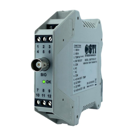
The CMCP500 Series incorporates a transducer "OK" circuit. This feature continuously monitors the
transducer bias and signal voltage. If this voltage exceeds (over or under) pre-set limits, the 4-20 mA output
current is reduced to less than 2 mA (typically 0 mA) to allow detection of the fault condition at the
associated PLC or DCS system. A green “OK" LED on the front of the unit ("ON" in an "OK" condition)
turns "OFF" to provide a local indication of the fault condition. This circuit will effectively detect open,
shorted, or reversed transducer connections. If a fault is detected that subsequently is repaired or goes
away, there will be a delay of approximately 30 seconds before the unit returns to the "OK" condition and the
"OK" LED turns back "ON". The detected fault will also disable the "ALERT" and "DANGER" alarms/relays
until the fault is removed and an "OK" condition exists.
2.4 Full Scale Range:
The CMCP500 Series is supplied factory calibrated for the full-scale range specified at the time of order.
The factory calibrated range is listed on the side label as a dash number. Custom ranges are available.
Range CMCP560 CMCP656 CMCP570
-01 0-250 Deg. F 0-250 Deg. F 0-250 Deg. F
-02 0-350 Deg. F 0-350 Deg. F N/A
-03 0-500 Deg. F 0-500 Deg. F N/A
-51 0-120 Deg. C 0-120 Deg. C 0-120 Deg. C
-52 0-175 Deg. C 0-175 Deg. C N/A
-53 0-260 Deg. C 0-260 Deg. C N/A
2.5 4-20 mA Output:
The primary output of the monitor/transmitter is the 4-20 mA current output which is proportional to the full
scale range of the unit. IE: If the range is 0 – 250 Deg F then 4 mA indicates a reading of 0 Degrees F and
20 mA indicates a reading of 250 Degrees F. This output is intended to drive a maximum resistive load of
600 Ohms with respect to system common at the PLC/DCS input. A precision 250 Ohm resistor is the
recommended load if the IO Module is not equipped. This will convert the 4-20 mA current reading into a 1-5
Vdc reading for the PLC/DCS. A short to ground (common) on this output will not damage it.
2.6 Buffered Output:
The CMCP570(A) provides buffered access to a 0-5Vdc, temperature proportional signal via a BNC
connector on the front of the unit. The buffered output signal is also available on a screw terminal at the top
of the unit.


