Stienen B.E. KL-6400 Series User manual
USER MANUAL
CLIMATE COMPUTERS
KL-6400 series
EN
© StienenBE / KL-6400-G-EN02000

Shut down power before opening the climate computer!
The climate computer contains exposed live parts!
Only to be opened by authorized personnel!
WARNING
Although utmost care has been given to the quality of this equipment during the design and manufacturing stages,
technical malfunctions can never be ruled out. The user should ensure that an adequate alarm system
and/or emergency provisions is/are in place to prevent any technical failure of the equipment and
peripheral facilities leading to danger to people, animals or property.
NOTE DOWN THE FOLLOWING IN CASE OF AN EMERGENCY
●Hardware and DIP switch settings
●Circumstances in which the emergency occurred
●Possible causes
●Software version number
KL-640 series includes the products: KL-6401, KL-6402, KL-6405 and KL-6410.
Please contact our Customer Service Department, if you have any questions. Be sure to have all necessary data at
hand. To ensure a speedy solution to the malfunction and to avoid any misunderstandings, it is advisable to note
down the cause and the circumstances in which the malfunction occurred before contacting us.
No part of this document may be reproduced or transmitted in any form or by any means, electronic or
mechanical, for any purpose, without the express written permission of StienenBE (www.StienenBE.com)
StienenBE accepts no liability for the contents of this manual and explicitly waives all implicit guarantees of
merchantability or fitness for a certain use. StienenBE also reserves the right to improve or change this manual
without being under the obligation to inform any person or organisation of any such improvement or change.
StienenBE cannot be held liable for any damage, loss or injury resulting from improper use or from use not in
accordance with the instructions in this manual.

CONTENTS PAGE
OPERATION 5
Temperature settings 8
OVERVIEW WINDOW 9
MAIN MENU 10
Access code 10
ROOM 11
Ventilation 11
Heating 16
Miscellaneous 17
Growth curves 18
Overviews 20
Alarm 21
Communication alarm 21
Climate alarm codes 22
ROOM STATUS 24
SENSORS 25
Outside temperature alarm 25
ALARM 26
Latest alarm for device 26
Latest alarms for rooms 26
SYSTEM 27
Language 27
Date/time 27
Display 27
Remote control 27
MAINTENANCE AND INSPECTION 28

If the software version of a module or peripheral device does not comply with the
requirements of the operating software, you have to perform a software update for the
module and/or peripheral device.
DO NOT USE A PRESSURE CLEANER ON THE RH OR CO2 SENSORS OR THE
MEASURING FAN
Remove the RH sensor and CO2 sensor from the room and store them
somewhere safe before cleaning the room. Also screw the protection caps
onto extension cable plugs to prevent water from penetrating into the
plugs. If the sensor is connected via a fixed socket outlet (FSO), push on
the flap of the fixed socket outlet until you hear it click (lock).
Application notes
Central ventilation
KL64CV-N-ENxxxxx
Compensations
KL64CS-N-ENxxxxx
Cooling KL64CC-N-ENxxxxx
Data communication between climate computers KL64DC-N-ENxxxxx
General description
KL64GD-N-ENxxxxx
Heat exchanger KL64HE-N-ENxxxxx
Heating controls KL64HC-N-ENxxxxx
MCA flap (central MCA flap) KL64MF-N-ENxxxxx
Remote control KL64RC-N-ENxxxxx
Timer (central timer) KL64TC-N-ENxxxxx
Ventilation control (air mixing fan, bypass flap, inlet flap etc.)
KL64VC-N-ENxxxxx
Attachments
AQC-G-Table
AQC-G-B-ALxxxxx
xxxxx = version number application note/attachment

Page 5 of 28
OPERATION
When the symbol is shown in the title bar and you press function key F3, the settings are displayed
graphically with the dot (●) showing the calculated value. Press F3 again to switch off the graphic display. Scroll
window
Scroll window
If a window contains more lines than the screen can display, the title bar will show the symbol. This symbol
indicates that you can call up the remaining settings and/or measurements using the up and down cursor keys
().
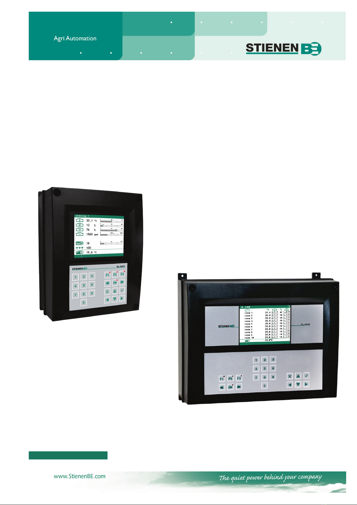
Keyboard
KL-6401
KL-6402 / KL-6405 / KL-6410
Whenever a key is pressed, the display will be lit for a couple of seconds so that you can also see the settings
and measurements in a dark animal house.
Note:
Only press the keys with the tip of your finger. Sharp objects such as a pen, pencil or screwdriver may
damage the keys!
The calculated setting may
differ from the value set by the
user, due to the growth curve
and/or compensations.
Window number
Window title
Column with settings and/or
measurements
Column with calculated and/or
corrected settings
Graph (function key F3)
Time & Date
You can use the keys to select
the previous room.
Room name
You can use the keys
to select the next room.
Scroll window
This manual suits for next models
4
Table of contents
Popular Industrial PC manuals by other brands


Dell
Dell Embedded Box PC 5000 Installation and operation manual

IBASE Technology
IBASE Technology ASB200-918 Series user manual

Lenovo
Lenovo ThinkCentre M90q Hardware Maintenance Manual

IXXAT
IXXAT Econ 100 Hardware manual

Kontron
Kontron KBox A-151-TGL user guide

AXIOMTEK
AXIOMTEK ICO500-518 Series user manual