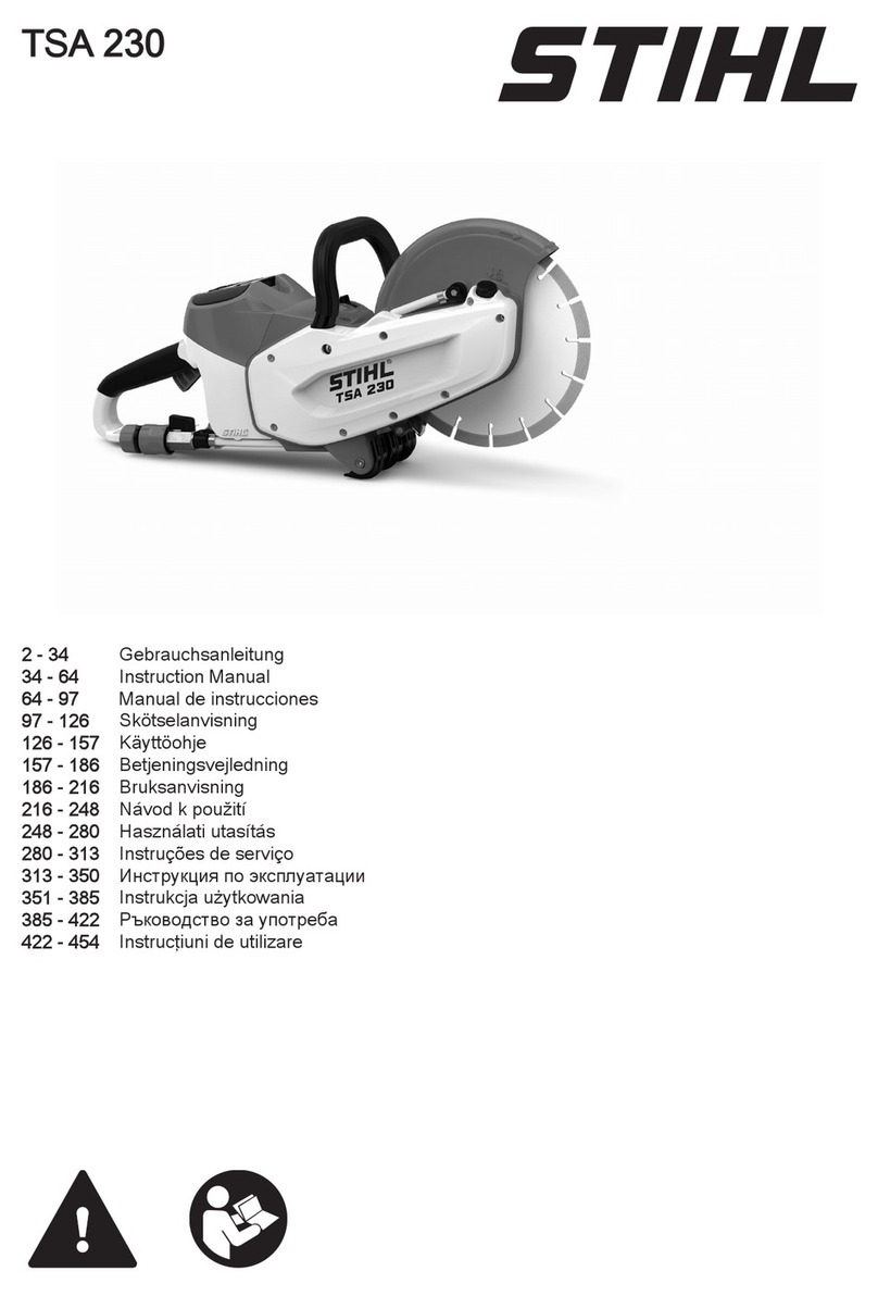
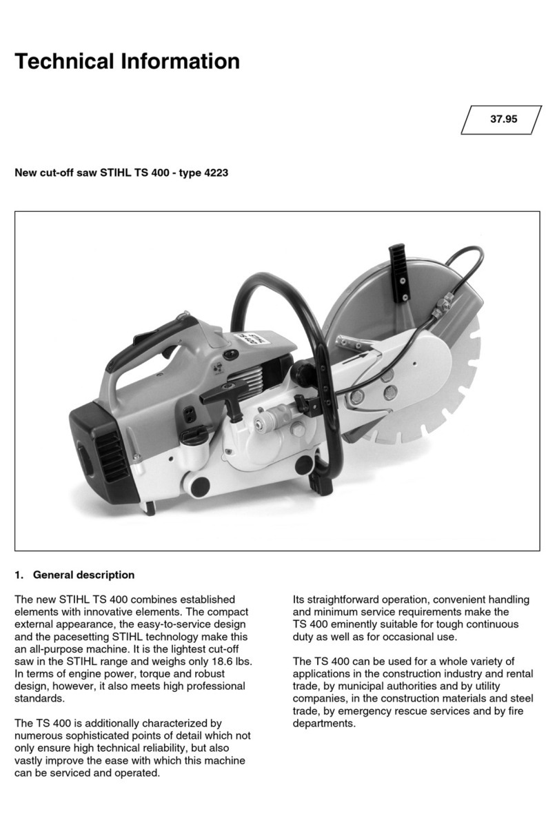
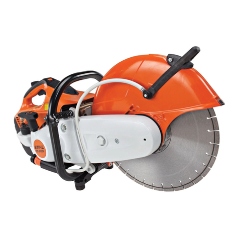
Stihl GS 461 User manual

STIH)
STIHL GS 461 2012-06

1GS 461
q
© ANDREAS STIHL AG & Co. KG, 2012
RA_761_00_01_01
1. Introduction and
safety precautions 2
1.1 Introduction 2
1.2 Safety precautions 3
2. Specifications 4
2.1 Engine 4
2.2 Fuel system 4
2.3 Ignition system 4
2.4 Tightening torques 5
3. Troubleshooting 7
3.1 Clutch 7
3.2 Chain Drive, Chain
Tensioner 8
3.3 Water system 9
3.4 Starter 10
3.5 Ignition system 11
3.6 Carburetor 12
3.7 Engine 15
4. Clutch 16
4.1 Clutch drum 16
4.2 Clutch 16
4.3 Pin / hand guard 18
4.4 Chain tensioner 19
4.5 Cut-off chain 20
4.6 Bar mounting studs 21
4.7 Collar nuts for chain
sprocket cover 21
5. Engine 22
5.1 Muffler 22
5.2 Leak testing 23
5.2.1 Preparations 23
5.2.2 Testing with
negative pressure 24
5.2.3 Pressure test 25
5.3 Oil seal on
ignition side 25
5.3.1 Oil seals on
clutch side 26
5.4 Shroud 27
5.5 Cylinder 28
5.6 Crankshaft 30
5.6.1 Ball bearing /
crankcase 34
5.7 Piston 35
5.8 Piston rings 37
5.9 Decompression valve 37
6. Ignition system 38
6.1 Ignition timing 38
6.2 Ignition module 38
6.3 Testing the ignition
module 40
6.3.1 Testing the ignition
module with engine
analyzer MDG 1 40
6.4 Spark plug boot /
ignition lead 41
6.5 Flywheel 42
6.6 Wiring harness 43
6.6.1 Testing 43
6.6.2 Ground wire 43
6.6.3 Wiring harness
Removal and
installation 43
6.6.4 Contact spring 46
6.7 Troubleshooting,
ignition system 48
7. Starter 51
7.1 General 51
7.2 Starter
Removal and
installation 51
7.3 Pawls 51
7.4 Rope rotor 52
7.5 Starter rope / starter
grip 52
7.6 Tensioning the
rewind spring 53
7.7 Replacing the
rewind spring 53
8. Antivibration
elements 55
8.1 Ring buffer fuel tank /
clutch side 55
8.1.1 Ring buffer fuel tank /
ignition side 55
8.1.2 Ring buffer guard /
clutch side 56
8.1.3 Ring buffer guard /
ignition side 57
8.1.4 Stop buffer on clutch
side 58
8.1.5 Stop buffer on ignition
side 58
8.2 Handlebar 58
8.3 Guard 59
8.4 Rubber buffers /
support 60
8.4.1 Water hose 60
8.4.2 Shut-off cock 61
8.4.3 Support 61
9. Actuating levers 63
9.1 Master Control lever 63
9.1.1 Removal and
installation 63
9.2 Throttle trigger /
trigger interlock 64
9.3 Throttle rod 65
10. Fuel system 67
10.1 Air filter 67
10.2 Filter base 67
10.3 Carburetor 67
10.3.1 Leakage test 69
10.4 Repairing
the carburetor 69
10.4.1 Metering diaphragm 69
10.4.2 Inlet needle 70
10.4.3 Pump diaphragm 71
10.4.4 Adjusting screws 72
10.5 Carburetor adjustment 74
10.5.1 Basic setting 74
10.5.2 Adjustment 74
10.5.3 Standard setting 75
10.6 Intake elbow 76
10.6.1 Impulse hose 77
10.7 Tank vent 78
10.7.1 Testing 78
10.7.2 Removal and
installation 78
10.8 Fuel intake 79
10.8.1 Pickup body 79
10.8.2 Fuel hose 79
10.8.3 Tank housing 80
11. Special tools 83
12. Service accessories 85
Contents

2GS 461
1. Introduction and safety precautions
1.1 Introduction
This Service Manual contains
detailed descriptions of all the
typical repair and servicing
procedures for this power tool.
Refer to the illustrated spare parts
lists during all repair work. These
lists show the installation position
and order in which the individual
parts and modules should be
assembled.
Refer to the latest edition of the
relevant spare parts list to check the
part numbers of any spare parts
required.
A fault on the machine may be due
to several causes. To help locate
the fault, consult the chapter on
"Troubleshooting" and the
"STIHL Service Training System"
for all functional groups.
Refer to the "Technical Information"
bulletins for engineering changes
which have been introduced since
publication of this Service Manual.
The "Technical information
bulletins" also supplement the spare
parts list and Service Manual until
an updated edition is issued.
The special tools mentioned in the
descriptions are listed in the chapter
"Special Servicing Tools" of this
manual. The tools can be identified
according to part number in the
"Special Tools Manual". The manual
lists all tools supplied by STIHL.
Symbols are included in the text and
pictures for greater clarity.
The meanings are as follows:
In the text:
:= Action to be taken
as shown in the illustration
above the text
– = Action to be taken
but not shown in the illustration
above the text
In the illustrations:
AItem pointer (short)
aDirection of movement (long
arrow)
b4.2 = Reference to another
chapter, in this case to
Chapter 4.2
Service Manuals and "Technical
information bulletins" are intended
exclusively for the use of properly
equipped repair shops. They must
not be passed on to third parties.
In order to be able to fit the machine
on the assembly stand, the support
5910 850 1651 mounting kit must
be used. The new support (1) can
be identified with the aid of the
marking "5910 851 1601 B" printed
on the housing.
2411RA001 TG
1
xxxx xxx xxxx x
– Remove support 5910 850 1650
:Secure the support (1)
5910 851 1601 B to the
assembly stand with two
screws (2) and washers.
The screws must not protrude, as
they may damage the housings
when clamping the machine,
depending on the model.
Preparing to make repairs
In order to be able to clamp the
machine for the repair work on the
assembly stand, the chain sprocket
cover, cut-off chain and guide bar
must be removed.
The machine is guided with the
collar screws through the lower
holes of the clamping rail and
fastened using nuts M 8 (arrows).
1
2
3
219RA000 TG
2411RA000 TG

3GS 461
Always use original STIHL
replacement parts.
They can be identified by the STIHL
part number,
the logo STIH)
and the
STIHL parts symbol (
The symbol may appear alone on
small parts.
Storage or disposal of fuel
Collect fuel in a clean container and
dispose of it in accordance with
environmental regulations.
Routing the leads
In principle, press all electrical leads
into the guides using the wiring tool
5910 890 4000.
1.2 Safety precautions
Specific national safety regulations
and the safety instructions in the
instruction manual must be
observed if the machine has to be
started up during maintenance or
repair work.
Fuel is highly inflammable and can
also be explosive under certain
conditions.
Do not bring any fire, flame, spark or
other source of heat near the fuel.
All work with fuel must be performed
outdoors only. Spilled fuel must be
wiped away immediately.
Test for leakage after all work on the
fuel system and engine.
Exercise extreme caution while
carrying out maintenance and repair
work on the ignition system. The
high voltages which occur can
cause serious or fatal accidents.
Suitable gloves must be worn
without fail if parts are heated for
assembly/disassembly purposes.
Improper handling may result in
burns and other serious injuries.
Always replace damaged parts.
Check dismantled parts for wear
and damage before installation,
replace if necessary.
Only use the machine with the
starter and shroud mounted –
otherwise the rotating flywheel
poses a risk of injury and there is a
risk of engine damage due to
overheating.
The chapter "Tightening Torques"
lists all components of this machine
that must be tightened with the
specified tightening torques or
coated with thread-locking
adhesive. These specifications
must be observed throughout the
Service Manual when tightening
screws and nuts as well as other
fasteners.
Fuel system – barbed connectors
Pull or push the fuel hoses, by hand
whenever possible, in the direction
of the connector in order to ensure
leakproofness of the fuel system.
Avoid damaging the barbed
connectors
– sharp-edged pliers, screwdrivers,
etc., may not be used.
Also, do not cut open fuel hoses
with a knife or similar aids.
Do not reuse fuel hoses after
disassembly, but instead always
replace them with new hoses
– fuel hoses can be overstretched
when being detached.
Mount new fuel hoses dry or using
STIHL press fluid
– apply press fluid to the ends of the
hose and the connectors, b12.
Other press fluids are not permitted
and may lead to fuel hose damage.


4GS 461
2. Specifications
2.1 Engine
GS 461
Displacement: 76.5 cm3
Cylinder bore: 52.0 mm
Stroke: 36.0 mm
Engine power according to ISO 7293: 4.3 kW (5.9 HP)
at 9800 rpm
Idle speed: 2500 rpm
Clutch: Centrifugal clutch without
linings
Clutch engages at: 3500 rpm
Crankcase leakage test
at gauge pressure: 0.5 bar
under vacuum: 0.5 bar
2.2 Fuel system
Carburetor leakage test at
gauge pressure: 0.8 bar
Operation of tank vent at
gauge pressure: 0.5 bar
Fuel: as specified in instruction
manual
2.3 Ignition system
Air gap between ignition
module and fanwheel: 0.20 (+ 0.1/- 0.25) mm
Spark plug (suppressed): BOSCH WSR 6 F
NGK BPMR 7 A
Electrode gap: 0.5 mm

5GS 461
2.4 Tightening torques
P and DG screws are fitted in plastic and light alloy metal parts. These screws form a permanent thread when
they are installed for the first time. The material is permanently deformed. Screws can be removed and installed
as often as necessary without impairing the strength of the screwed assembly, provided that the specified
tightening torque is observed.
For this reason it is essential to use a torque wrench.
When inserting DG and P screws into an existing screw thread:
Insert the DG or P screw in the hole and turn counterclockwise until it gently drops into the hole in axial direction
and engages the existing threads. Tighten the screw clockwise to the specified torque.
This procedure ensures that the screw engages properly in the existing thread and does not form a new thread
and weaken the assembly.
For the microencapsulated screw, before renewed assembly, clean both threads (insert tap in the internal thread
by hand and then blow out the threaded hole, brush off the exterior thread), coat the cleaned screw with
medium-strength Loctite 242 or 243.
Screwdriver speed with: P and DG screws max. 500 rpm.
Do not use an impact wrench to release or tighten screw connections.
Screws with and without locking serration must not be confused.
Fastener Thread size For component Tightening
torques
Nm
Comment
Screw M 4x12 Cover for chain tensioner / crankcase 3.0
Stud M 8 Stud / crankcase for bar 23.0 2)
M 10x1 Decompression valve 14.0
Screw D 4x12 Spring housing / fan housing 3.0
Collar nut M 5 Filter cover / slotted nut 1.0
Collar nut M 5 Flange / filter base / carburetor 3.5
Screw M 4x10 Flange / crankcase 2.5 5)
Screw M 4x12 Crank drive flange / crankcase 3.5 4), 6)
Screw P 6x21.5 Handlebar at top / tank housing 8.0 3)
Screw P 6x32.5 Handlebar at bottom / tank housing 8.0 3)
Screw P 4x19 Handle molding 1.6
Screw D 4x16 Hand guard clutch side 4.0 4), 6)
Screw M 5x35x22 Hand guard ignition side 7.0 4), 6)
Screw M 5x23 Shroud / crankcase 6.0
Nut M 5 Shroud / cylinder 3.5
Screw M 5x25 Crankcase drive side / fan side 10.0 4), 6)
Screw M 5x20 Fan housing 7.0 4)
Carrier M 12x1 L Carrier 50.0
Screw M 4x16 Ring buffer / crankcase 4.5 5)
Screw P 6x19 Ring buffer / tank housing rear 5.5

6GS 461
Fastener Thread size For component Tightening
torque
Nm
Comment
Screw P 6x32.5 Ring buffer / tank housing rear ignition side top 5.5
Screw P 6x19 Ring buffer / tank housing front 5.5
Screw M 6x30 Muffler / crankcase 15 4), 6), 8)
Screw M 5x16 Muffler / cylinder 11.5 1), 4), 6)
Screw M 5x6 Muffler top 6.5 1), 4), 5)
Nut M 8x1 Flywheel / crankshaft 33.0 7)
Screw M 4x8 Side plate / crankcase 3.0 4), 6)
Screw M 3x20 Clamp / manifold 0.5
Screw P 4x14 Water attachment / handle housing 2.0
M 14x1.25 Spark plug 25.0
Screw M 5x20 Ignition module / crankcase 7.0 5)
Screw M 6x30 Cylinder / crankcase 15.0 4), 6)
Remarks:
1) Loctite 242 or 243 medium strength
2) Loctite 270 high strength
3) Loctite 649 very high strength
4) Screws with locking serration
5) Microencapsulated screws
6) Screws with easy-slide coating
7) Connection between crankshaft and flywheel must be degreased and oil-free
8) Coat screws and threaded hole with medium-strength Loctite 242 or 243

7GS 461
3. Troubleshooting
3.1 Clutch
Problem Cause Remedy
Cut-off chain becomes stuck under
full load
Clutch shoes badly worn Replace clutch
Clutch drum badly worn Replace clutch drum
Cut-off chain runs when idling Idle speed too high Readjust idle speed screw LA
Tension springs of the clutch shoes
are stretched
Replace clutch springs or replace
clutch
Tension springs of the clutch shoes
are broken
Replace clutch springs
Loud noises Tension springs stretched Replace all clutch springs
Needle cage damaged Replace needle cage
Clutch shoe retainer broken Replace retainer or clutch
Clutch shoes and carrier worn Replace clutch

8GS 461
3.2 Chain Drive, Chain Tensioner
Problem Cause Remedy
Chain sprocket wears rapidly Cut-off chain not properly tensioned Tension cut-off chain properly
Insufficient cooling of cut-off chain Check water cooling
Insufficient water volume Check water pressure
Cut-off chain becomes stuck under
full load
Clutch shoes badly worn Replace clutch
Clutch drum badly worn Replace clutch drum
Cut-off chain runs when idling Idle speed too high Readjust idle speed screw LA
Tension springs of the clutch shoes
are stretched
Replace clutch springs or replace
clutch
Tension springs of the clutch shoes
are broken
Replace clutch springs

9GS 461
3.3 Water system
Problem Cause Remedy
No water supply Shut-off cock, connectors of hose
connections or opening of water
outlet very dirty / clogged
Clean shut-off cock and connectors
of hose connections, replace if
necessary
Too little water Water hose kinked or damaged –
also check water supply hose
Check hose clips, water hose and
seals, replace if necessary
Connectors of hose connection
very dirty
Check and clean connectors,
replace if necessary
Leaks in the water system O-ring on water attachment
damaged
Replace O-ring, replace whole
water attachment if necessary
Hose clips open or damaged or
hose damaged
Close hose clips, replace if
necessary, replace damaged hose

10 GS 461
3.4 Starter
Problem Cause Remedy
Starter rope broken Rope pulled out too vigorously as
far as stop or over edge, i.e. not
vertically
Replace starter rope
Normal wear Replace starter rope
Starter rope does not rewind Heavy fouling or rust on rewind
spring
Clean or replace rewind spring
Spring insufficiently tensioned Check rewind spring and increase
tension
Rewind spring broken Replace rewind spring
Starter rope cannot be pulled out
far enough
Rewind spring overtensioned Check rewind spring and reduce
tension
Starter rope can be pulled out
almost without
resistance (crankshaft does not
turn)
Guide peg on pawls or pawls
themselves are worn
Replace pawls
Spring clip fatigued Replace spring clip
Spring clip improperly installed Install spring clip properly
Starter rope is difficult to pull or
rewinds very slowly
Starter mechanism is very dirty Thoroughly clean complete starter
mechanism
At very low outside temperatures:
Lubricant oil on the rewind spring
becomes viscous (spring winding
stick together) or moisture has
penetrated the rewind spring
(spring windings are frozen)
Coat rewind spring with a little
standard solvent-based degreasant
(containing no chlorinated or
halogenated hydrocarbons), then
pull rope carefully several times
until normal action is restored

11GS 461
3.5 Ignition system
Exercise extreme caution while
carrying out maintenance and
repair work on the ignition system.
The high voltages which occur can
cause serious or fatal accidents.
Problem Cause Remedy
Engine runs roughly, misfires,
temporary loss of power
Spark plug boot is loose Press spark plug boot firmly onto
spark plug and fit new torsion
spring and spark plug boot if
necessary
Spark plug sooted, smeared with oil Clean spark plug, replace if
necessary
In the event of repeated sooting,
check air filter
Ignition lead loose in ignition
module
Replace ignition lead
Fuel / oil mixture
– contains too much oil
Use a fuel mixture with the correct
mixing ratio
Incorrect air gap between ignition
module and flywheel
Set the correct air gap
Flywheel is cracked
or has other damage or pole shoes
have turned blue
Install new flywheel
Incorrect ignition timing, flywheel
out of adjustment
– woodruff key has sheared off or
groove in flywheel is worn
Replace flywheel or woodruff key
Weak magnetization in flywheel Install new flywheel
Irregular spark Check operation of switch shaft /
contact spring and ignition module
Damaged insulation on ignition lead
or interruption in ignition lead or
short circuit wire, check ignition
lead / ignition module and replace if
necessary.
Check operation of spark plug
Clean spark plug, replace if
necessary
If the engine runs roughly, this may also be due to problems in the carburetor or engine.

12 GS 461
3.6 Carburetor
Problem Cause Remedy
Carburetor floods; engine stalls Inlet needle not sealing
– Foreign matter in valve seat or
cone
Remove and clean inlet needle or
clean carburetor
Inlet needle worn Replace inlet needle
Inlet control lever sticking on
spindle
Check inlet control lever, replace if
necessary
Helical spring not located on nipple
of inlet control lever
Remove the inlet control lever and
refit it correctly
Perforated disc on diaphragm is
deformed and presses constantly
against the inlet control lever
Fit new metering diaphragm
Metering diaphragm is deformed Fit new metering diaphragm
Poor acceleration Low speed adjusting screw "too
lean"
Check basic carburetor setting,
correct if necessary
High speed adjusting screw "too
lean"
Check basic carburetor setting,
correct if necessary
Inlet needle sticking to valve seat Remove inlet needle, clean and
refit
Metering diaphragm or gasket is
damaged
Replace metering diaphragm and
gasket
Tank vent faulty Replace tank vent
Leak in fuel line between pickup
body and carburetor
Seal connections or replace fuel
line

13GS 461
Problem Cause Remedy
Engine will not idle, idle speed too
high
Throttle shutter opened too wide by
idle speed screw LA
Set idle speed screw LA correctly
Oil seals / crankcase leaking Seal or replace oil seals /
crankcase
Throttle shutter does not close Replace carburetor
Engine stops when idling Idle jet bores
or ports blocked
Clean the carburetor
Low speed adjusting screw "too
rich" or
"too lean"
Correct setting of low speed
adjusting screw L
Idle speed screw LA
setting incorrect – throttle shutter
completely closed
Set idle speed screw LA correctly
Tank vent faulty Replace tank vent
Leak in fuel line between pickup
body and carburetor
Seal connections or replace fuel
line
Cut-off chain rotates at idle speed Idle speed too high Readjust with idle speed screw
LA (counterclockwise)
Tension springs of clutch shoes
stretched or fatigued
Replace tension springs or replace
clutch
Anchor loops of the tension springs
for the clutch shoes are broken
Replace tension springs

14 GS 461
Problem Cause Remedy
Engine speed drops quickly under
load – low power
Air filter dirty or wet Clean or dry air filter, replace if
necessary
Throttle shutter not opened fully Check throttle cable and rod
Tank vent faulty Replace tank vent
Fuel pickup body dirty Replace pickup body
Fuel strainer dirty Clean fuel strainer in carburetor,
replace if necessary
Leak in fuel line between pickup
body and carburetor
Seal connections or replace fuel
line
High speed adjusting screw H"too
rich"
Check basic carburetor setting,
correct if necessary
Main jet bores or ports blocked Clean the carburetor
Pump diaphragm damaged or
fatigued
Fit new pump diaphragm
Incorrect ignition timing, flywheel
out of adjustment
– woodruff key has sheared off or
groove in flywheel is worn
Replace flywheel or woodruff key
Engine runs extremely rich, lacks
power and has very low final speed
Choke shutter does not open fully Examine the carburetor and starter
shaft and repair or replace if
necessary

15GS 461
3.7 Engine
Always check and, if necessary,
repair the following parts before
looking for faults on the engine:
- Air filter
- Fuel supply
- Carburetor
- Ignition system
Problem Cause Remedy
Engine does not start easily, stalls
at idle speed but operates normally
at full throttle
Oil seals in crankcase damaged Replace oil seals
Crankcase leaking or
damaged (cracks)
Seal / replace crankcase
Engine does not deliver full power
or runs erratically
Piston rings worn or broken Replace piston rings
Muffler / spark arresting screen
carbonized
Clean muffler (inlet and outlet
openings), replace spark arresting
screen, replace muffler if necessary
Air filter dirty or wet Clean or dry air filter, replace if
necessary
Fuel line kinked or cracked Fit new lines and ensure they are
installed without kinking
Decompression valve not closed Close decompression valve, check
and replace if necessary
Engine is overheated Insufficient cylinder cooling. Air
inlets in fan housing blocked or
cooling fins on cylinder very dirty
Thoroughly clean all cooling air
openings and the cylinder fins
Air intake in fan housing is fouled Clean air intake on fan housing

16 GS 461
4. Clutch
4.1 Clutch drum
:Remove cap (1)
:Push out circlip (1) and remove
washer (2) – always use new
circlip
:Remove the clutch drum (3)
:Remove needle cage (1)
– Clean needle cage and
crankshaft stub, b12
1
2411RA002 TG
3
2411RA162 TG
2
1
3443RA047 TG
1
– Coat the needle cage and
crankshaft stub with STIHL
grease, b12
– Examine the clutch drum (1) for
signs of wear
The remaining thickness must be
measured if there are distinct signs
of wear on the inside diameter of the
clutch drum (1). The clutch drum
must be replaced if the remaining
thickness is less than approx. 80 %
of the original thickness.
Installation
– Install the clutch drum
– Coat cap with STIHL press fluid,
b12
– Fit rim sprocket and press on cap
until the groove completely
enclose the clutch drum
4.2 Clutch
– Troubleshooting, b3
– Remove filter cover
– Remove air baffle
– Take off the spark plug boot and
remove the spark plug
!
80%
100%
5902RA018 TG
1
:Insert locking strip (1)
0000 893 5903 into the cylinder
with the wide side in front and
align so that the words "OBEN-
TOP" are visible
:Locking strip (1) 0000 893 5903
must rest against the cylinder
wall (arrow)
– Position as shown
– Remove rim sprocket and clutch
drum
3443RA004 TG
1
3443RA493 TG
1

17GS 461
:Unscrew the clutch (1) at
hexagon (arrow)
The clutch has a left-hand thread.
Disassembly
:Use hook (2) 5910 890 2800 to
remove the clutch springs (1)
If there are distinct signs of wear of
the clutch kit (set of 3), replace
clutch shoes.
Assembly
:Fit holder (1) and slide clutch
shoes (2) over the legs (3)
TOP
1
2411RA003 TG
off
off
off
5902RA006 TG
21
off
3443RA464 TG
31
2
Attach the springs to the side with
the raised hexagon (arrow).
– clamp assembled clutch on a
horizontal clutch shoe in the vise
:Attach one end of the clutch
spring (1) to the clutch shoes
:Use the assembly hook (2)
5910 890 2800 to pull the other
end of the spring and hook it into
the clutch shoe
– Examine the clutch – all springs
must be hooked in properly
The washer (1) must be in place
and the word "TOP" (arrow) must be
visible.
off
off
5902RA012 TG
1
2
TOP
1
2411RA004 TG
:Fit the clutch (1) on the
crankshaft stub so that the raised
hexagon (arrow) can be seen
:Screw on and tighten the
clutch (1) – left-handed thread
– Pull the locking strip out of the
cylinder
– Fit rim sprocket and clutch drum
– Fit the spark plug and tighten it
down firmly
– Refit the spark plug boot
– Insert air baffle
– Attach filter cover
TOP
1
2411RA005 TG

18 GS 461
4.3 Pin / hand guard
The pin ensures that the hand guard
is securely mounted. If it is worn,
replace the pin.
– Remove starter, b7.2
:Pull out rubber buffer (1)
:Unscrew the screw (1)
:Draw hand guard (2) with
insert (3) off the pivot pin
simultaneously
– Pull insert out of hand guard
– Remove washer
1
2411RA006 TG2411RA007 TG
1
2
3
:Disassemble bolt (1)
Installation
– Coat the knurled area of the new
pin with Loctite before fitting the
pin, b12
:The pin must be inserted in the
hole (arrow) so that the knurling
on the pin engages the knurled
profile
Turn the pin back and forth slightly
until it fits.
The pin must be driven in square.
2411RA008 TG
1
2411RA009 TG
:Drive in pin (1) in accordance
with the following information
:Pin (1) a =
approx. 10.3...10.5 mm
:Orient insert (1) so that the
tab (2) is at the top
:Slide insert (1) into recess in
hand guard (3) until the holes (4)
and (5) are lined up
2411RA010 TG
1
a
1
2411RA011 TG
2411RA012 TG
1
25
4
3

19GS 461
:Slide on the washer (1)
:Slide hand guard (1) with
insert (2) across the machine as
far as it will go on the pivot pin
(arrow)
:Screw in the screw (3) and
tighten
:Align rubber buffer (1) so that the
pegs face the machine and the
raised part (2) faces upwards
1
2411RA013 TG
2
3
1
2411RA014 TG2411RA015 TG
21
– Use STIHL press fluid to simplify
assembly, b12
:Press rubber buffer (1) into the
mount so that the raised part (2)
rests against the hand guard
(arrow)
– Reassemble remaining parts in
reverse order
4.4 Chain tensioner
– Troubleshooting, b3.2
– Remove outer side plate,
b8.1.2
:Turn the spur gear (1)
anticlockwise until the tensioner
slide (2) makes contact on the left
and the tensioning nut is visible
:Unscrew the screw (3)
2411RA016 TG
1
2
3
:Hook assembly hook
5910 890 2800 onto tensioning
nut (arrow) and pull out the
complete chain tensioner
– Remove sealing ring from shaft
– Examine the chain tensioner,
replace if necessary
Installation
:Fit new sealing ring in the groove
(arrow) of the spur gear
– Clean all disassembled parts,
b12
– Grease screw threads, gear
wheels and sealing ring with
STIHL grease, b12
– Before fitting the chain tensioner,
assemble the individual parts and
push limit stop into the mount
2411RA017 TG
3443RA466 TG
Other manuals for GS 461
5
Table of contents
Other Stihl Saw manuals

Stihl
Stihl MSA 300.0 User manual

Stihl
Stihl TS 410 User manual

Stihl
Stihl MSA 161 T User manual

Stihl
Stihl MS 18 Building instructions

Stihl
Stihl MS 241 C-M User manual

Stihl
Stihl MSA 220 C User manual

Stihl
Stihl MS 500i User manual

Stihl
Stihl TS 400 Cutquick Manual

Stihl
Stihl TS 700 User manual

Stihl
Stihl GS 461 User manual

Stihl
Stihl TS 400 Cutquick User manual

Stihl
Stihl MSA 160 T User manual

Stihl
Stihl TS 700 User manual

Stihl
Stihl GTA 26 User manual

Stihl
Stihl TS 700 User manual

Stihl
Stihl MDG 1 User manual

Stihl
Stihl MS 260 User manual

Stihl
Stihl TS 700 User manual

Stihl
Stihl MS 460 User manual

Stihl
Stihl MSA 160 C User manual