Stiles Ironwood CUT 18 User manual
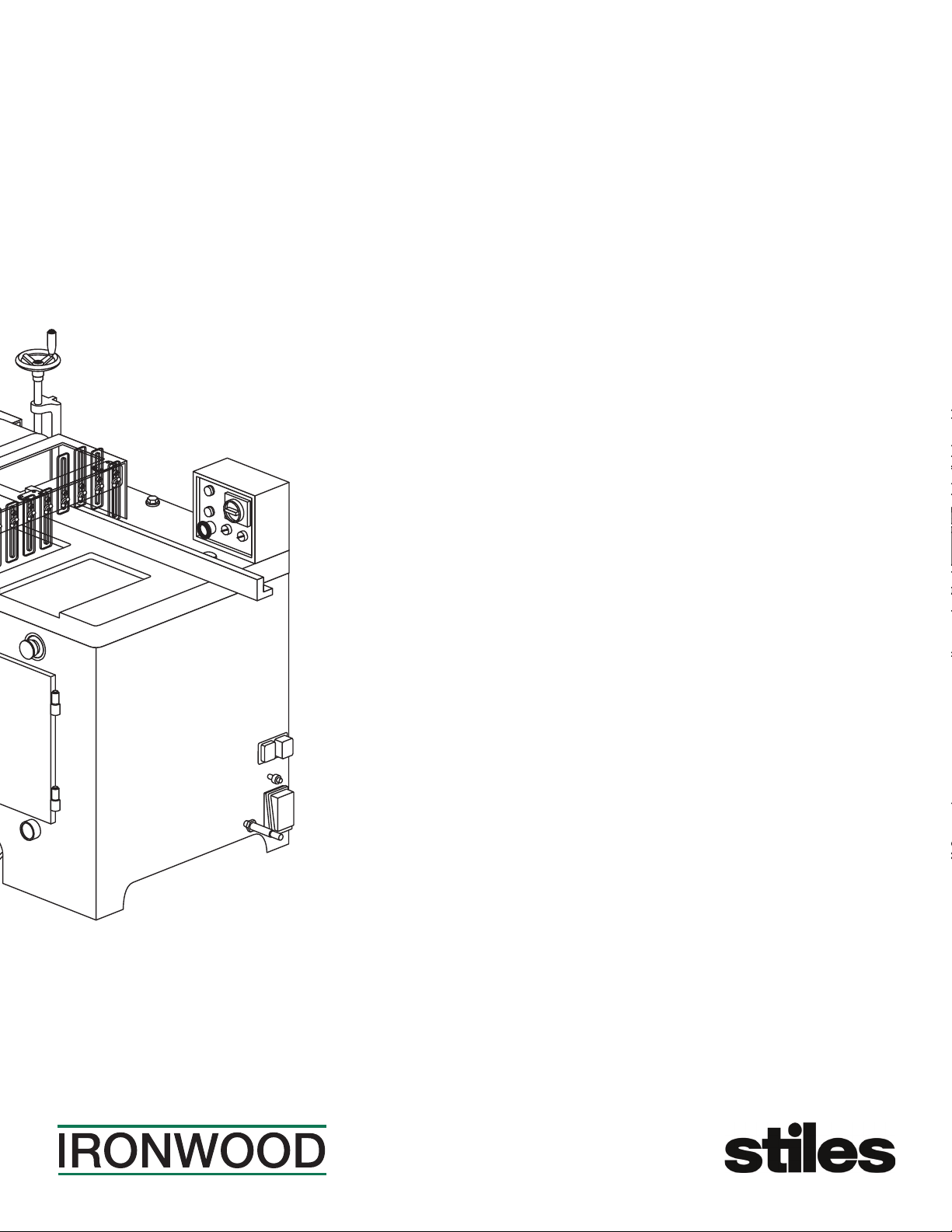
Ironwood CUT 18
User Manual
general information. features.
adjust air pressure. cutting the workpiece.
maintenance. adjust v-belt tension.
troubleshooting. electrical diagram.
delivery and installation. inspection.
receiving the machine. assembly.
dust exhaust outlet. operation and adjustments.
technical specifications. safety considerations.
connect to power. safety.

Ironwood CUT 18 | User Manual2
1.0 General Information ................................................................ 3
1.1 Thank You!
1.2 Before Contacting Stiles
1.3 Features
1.4 Intended Use
1.5 Technical Specifications
1.6 Safety Considerations
2.0 Facility Preparation ................................................................. 6
2.1 Floor
2.2 Work Space
2.3 Power
3.0 Delivery and Installation ............................................................. 7
3.1 Receiving Your Machine
3.2 Unpack the Machine
3.3 Inspection
3.4 Move Machine to Final Position
3.5 Remove Machine from Pallet
3.6 Level
3.7 Pre-Operation Cleaning
4.0 Assembly ....................................................................... 10
4.1 Saw Blade
4.2 Dust Exhaust Outlet
4.3 Safety Guard Assembly
5.0 Connect to Power ................................................................ 12
6.0 Safety.......................................................................... 13
7.0 Operation and Adjustments ......................................................... 14
7.1 Control Panel
7.2 Emergency Stop
7.3 Pneumatic Control
7.4 Adjust Hold-Down Clamp
7.5 Adjust Air Pressure
7.6 Adjust Fence Squareness to Saw Blade
7.7 Cutting the Workpiece
8.0 Maintenance..................................................................... 18
8.1 Cleaning
8.2 Lubrication
8.3 Change the Saw Blade
8.4 Adjust V-Belt Tension
8.5 Replace V-Belts
9.0 Troubleshooting .................................................................. 20
9.1 Air Circuit Diagram
9.2 Electrical Diagram
Table of Contents
PLEASE REVIEW AND OBSERVE ALL SAFETY
INFORMATION / DIRECTIVES BEFORE INSTALLING,
OPERATING, OR PERFORMING MAINTENANCE ON
THIS MACHINERY.

Ironwood CUT 18 | User Manual 3
1.0 General Information
1.1 Thank You!
Thank you for your purchase of the Ironwood CUT 18 cut-off saw.
At Stiles Machinery, our goal is to ensure that you are fully satisfied
with your purchase. This manual is provided so that you may
properly assemble, operate, and maintain your CUT 18. Should you
need help, our team of dedicated service personnel are available to
answer your questions and provide any resource recommendations
you may need.
Warranty and Support
All Ironwood machines are designed to meet the exacting standards
demanded by craftsmen like you. Ironwood machines include a
one (1) year parts warranty and two (2) years of free 24/7 technical
support beginning at date of shipment. Standard technical support
remains in effect for free for the lifetime of the machine thereafter.
Warranty service work is not covered by manufacturer’s warranty.
Stiles’ service team is available for an additional charge.
1.2 Before Contacting Stiles
Please have your machine model and serial number available when
contacting Stiles Machinery with questions. The machine’s model
and serial numbers are listed on the metallic plate located on the
machine’s frame.
Information regarding the electrical system and pneumatic supply
are also listed on the metallic plate.
Stiles Technical Support
616.698.6615
Stiles Parts
800.PARTS.80 (800.727.8780)
Website
www.stilesmachinery.com/ironwood/cut18
Machine Model ____________________________________________
Machine Serial Number _____________________________________
1.3 Features
• A convenient foot pedal, or dual push buttons (depending on
saw configuration) controls the pneumatic operation of the
cutting cycle; air pressure is used to raise the saw blade and
lower the hold-down clamp.
• Solid steel construction and a precision ground table surface
ensure cutting accuracy and stability during heavy cutting
operations.
• Accommodates an 18" saw blade.
• Cutting capacity: up to 4" thick and 12" wide. See section 7.4 for
cutting capacity chart.
• Door safety switches ensure safe tool changes; access doors
can be opened only after blade has stopped rotating.
• Powerful, high-torque, 10-hp motor provides stability at fast
cutting speeds.
• Safety guard improves operator safety.
• 4" diameter dust extraction port keeps work area clean.
• Hold-down clamp adjusts to workpiece thickness.
• Doors are locked and unlocked only with a special unlocking
handle.
1.4 Intended Use
Use your CUT 18 for accurate, safe, and reliable wood crosscutting
for workpieces up to 4" thick and up to 12" wide. Rugged cast iron
construction and powerful motor ensure stability for heavy cutting
operations.
Performance and dependability are optimized when the machine is
operated with care and maintained properly. When used according
to the instructions in this manual, you can expect years of trouble-
free operation.

Ironwood CUT 18 | User Manual4
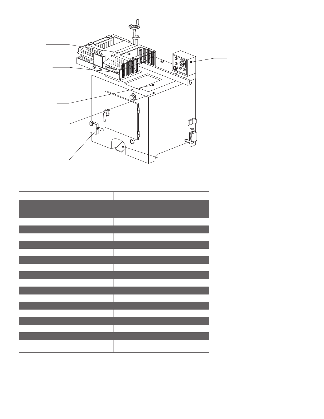
Convenient and
easy-to-use control
panel handles all
control functions
Adjustable ngers
on the fence protect
the operator from the
cutter and add
support for the
workpiece.
Safety guard
for improved
operator safety
Generous table size
provides support for
larger workpieces
Large, cast iron,
ground and polished
table is rugged and
stable, with maximum
rigidity for heavy
cutting operations
Door lock safety switch Foot pedal for pneumatic
operation of saw
1.5 Technical Specifications
Description Ironwood CUT 18
Cutting capacity (thickness x width)
2" x 12", 3" x 11", 4" x 10"
(51mm x 305mm, 76mm x 280mm,
102mm x 254mm)
Cycle speed 45 cpm (cuts/min)
Cycle operation Pneumatic
Air pressure requirement 80-90 psi
Air consumption 12 cfm @ 45 cpm
Saw blade size 18" (457mm)
Saw arbor diameter 1" (25.4mm)
Saw blade speed 3,200 rpm
Dust port diameter 4" (102mm)
Dust extraction requirements 450 cfm @ 4,500 feet/min.
Motor 10 hp
Power 230 v (3 phase) 460 v (3 phase)
Amperage 25 amps (@ 230 v) / 12.5 amps (@460 v)
Table size 26" x 27
1⁄2" (660mm x 700mm)
Working table height 34¼" (870mm)
Net weight 771 lbs. (350 kgs)
Gross weight 903 lbs. (410 kgs)
Packing dimensions (L x W x H) 35 1⁄2" x 31
1⁄2" x 53⁄2"
(900mm x 800mm x 1,350 mm)

Ironwood CUT 18 | User Manual 5
1.6 Safety Considerations
For your safety, read these instructions thoroughly before you install
and operate this machine. Always have these instructions available
at the machine for reference.
Observe all codes and regulations that apply to the installation and
operation of this machine.
Keep visitors at a safe distance from the workspace.
Keep children away from this and all machines. Childproof your
work area!
Familiarize yourself with the safety notices used in this manual.
Caution
If cautions are ignored, personal injury and/or machine damage
may result.
WaRninG
If warnings are ignored, serious injury or death may result.
Warning Labels
This machine has warning labels attached to ensure safe operation.
These warning labels are very important and should be kept clean
and never be removed. If warning labels become damaged or lost,
contact Stiles Machinery immediately for replacements.
Label 1 Keep hands out of this area
Label 2 Do not operate the CUT 18 when the saw blade access
door is open
Label 3 Always wear ear and eye protection
Label 4 Safety instructions for operating the CUT 18
LABEL NO. 1 LABEL NO. 2
LABEL NO. 3 LABEL NO. 4
WaRninG
Never use the CUT 18 for purposes other than its intended use. Do
not modify or remove any guards or other safety features. Improper
use or modifications may affect your warranty or result in serious
injury or death.
Training
This machine is intended for use by authorized, well-trained
operators only.
Do not operate this machine until you have a complete working
knowledge of this saw and have been properly trained for its
safe operation, correct adjustment, and use. All operators should
thoroughly read and understand this manual and the workings of
this machine prior to operation.
It is essential that all operators be aware of the following:
• The dangers associated with the operation of this machine.
• The use of personal protective equipment for ear and eye
protection.
• The proper positioning of the operator and operator’s hands
relative to the saw blade and pneumatic hold down clamp.
• The principles of machine operation, and proper use and
adjustment of the fence, jigs, safety guards, extension tables and
end stops.
• The correct selection of tooling for each operation.
• The safe handling of the workpiece when cutting.
• The safe stacking of the workpiece before and after cutting.
NOTE: Dust extraction equipment must be connected and turned on
before starting all machine operations.

Ironwood CUT 18 | User Manual6
2.0 Facility Preparation
Prior to uncrating your machine confirm that your location can
accommodate the Ironwood CUT 18. Follow these guidelines:
2.1 Floor
• The floor must be flat and level.
• Although no special foundations are required, a concrete floor is
recommended.
• All floors must have a load-bearing strength suitable for the
machine weight of approximately 800 pounds.
• The machine need not be anchored to the floor. However, if you
decide to do so, purchase high quality anchor bolts appropriate
to the floor construction and material.
2.2 Work Space
• Provide adequate work space surrounding the machine.
• Provide proper non-glare, overhead lighting to keep the work
space well lit.
• Place the machine so that any potential kickback area is not in
line with aisles, doorways, or other work and traffic areas.
• Provide an adequate dust extraction system. The dust extraction
system should have a flow rate of 4500 feet/min at 450 cfm.
• Avoid exposure to any environment where vibration is present.
• Avoid exposure to direct sunlight or heat.
1'-6"*
(500mm)
(work area)
1'-6"
(500mm)
(work area)
2'-0"
(600mm)
(work area)
7'-6"
(2300mm)
(work area)
1'-6"*
(500mm)
(work area)
6'-6"
(2000mm)
(work area)
Machine clearance requirements*
*Actual clearance requirements may vary depending on length of
material to be cut.
2.3 Power
WaRninG
A licensed electrician must connect the CUT 18 to the building
power source.
• Do not use extension cords.
• Be sure that the electrical current of the power source is of the
same characteristics as the electrical system supplied with your
machine. If other machine voltage capabilities are required,
contact Stiles Machinery.
• Provide access to a suitable power source.
CUT 18
Motor 10 HP
Motor Power 230v (3 phase) /
460v (3 phase)
Amperage 25 amps (230v) /
12.5 amps (460v)
• Ensure the machine is protected with an external over-current
protective device per your local electrical codes.
• Electrical equipment operating conditions:
Air temperatures between +41ºF (+5ºC) and +113ºF (+45ºC).
Relative humidity not to exceed 50% at a maximum temperature
of +113ºF (+45ºC).
• Electrical equipment is designed and protected to withstand the
effects of transportation and storage temperatures within a range
of -13ºF (-25ºC) to +131ºF (+55ºC), and for short periods of time
not exceeding 24 hours at up to +158ºF (+70ºC).
• Ensure connection to factory ground system is wired correctly
(according to IAW local electrical codes and National Electric
Code) and not connected to any electromagnetic interference
source such as welders.

Ironwood CUT 18 | User Manual 7
3.0 Delivery and Installation
3.1 Receiving Your Machine
You will be contacted to arrange delivery. Your machine will be
delivered by truck to your location. If there is no loading dock,
be sure that you have informed the carrier in advance so that
they deliver using a truck with a lift gate to lower the machine to
ground level.
Before accepting the machine and signing the bill of lading from the
carrier, please inspect crating and machine condition, note potential
damage on the bill of lading, take pictures of potential damage, and
contact Stiles Machinery immediately at 616.698.7500 and ask to
speak with the traffic department.
The machine will arrive fully crated and secured to a pallet. Use a
hand truck or fork lift to move the machine on its pallet as close to
its final position as possible.
If you do not intend to install the Ironwood saw immediately after
delivery, store it in a protected, cool, and dry location.
The machine
arrives fully crated.
Remove and save the
paperwork attached to
the outside.
3.2 Unpack the Machine
TOOLS REQUIRED:
• Hammer
• Crowbar
Unpack as follows:
Do not remove the machine from the pallet.
1. Remove and save all paperwork attached to the outside of
the crate.
2. Remove the crating, starting with the top, then remove the four
sides. Use caution to avoid personal injury and prevent damage
to the machine’s finish.
3. Remove the protective plastic from the machine, starting at
the bottom.
Remove the crating,
starting with the top,
then remove the fou
r
sides.
4. Remove the plastic sleeve from the front access door handle.
The door is locked when the handle is in the vertical position.
Turn the handle to the right to unlock and open the access
door.

Ironwood CUT 18 | User Manual8
5. Remove the hardware, accessories, and a tool kit that are
shipped with the machine, noting that some hardware and
accessories may be located inside the machine. If additional
accessories are ordered, they may be delivered separately.
Remove any parts
that may be stored
inside the machine.
6. Close and lock the front access door.
3.3 Inspection
Save all containers and packing materials until you are satisfied
that your machine has arrived in good condition. If you discover the
machine is damaged after you’ve signed for delivery, immediately
call Stiles Customer Service at 616.698.7500.
When you are completely satisfied with the condition of your
equipment, you should inventory its parts.
Open and check the contents of all containers to ensure all tools,
hardware, and accessories are included. The tool kit should contain
the following items:
1. 19mm T-wrench
2. 5mm Allen wrench
3. Door key/handle
4. Adjustment handle
5. Leveling plates and bolts
6. Dust port connection
7. Acrylic fingers for infeed of safety guard
8. Paint (2-color set)
9. User manual
3.4 Move Machine to Final Position
Be sure the site is properly prepared. Refer to section 2.0 for details.
Be sure the front and side access doors are closed and locked
before transporting.
TOOLS REQUIRED:
• Hand truck or fork lift
Use a hand truck or fork lift to move the machine on its pallet to its
final location. If using a fork lift, make sure fork travel is clear of any
obstacles.
Use a hand truck
or fork lift to move
the machine.
3.5 Remove Machine from Pallet
Caution
The CUT 18 weighs approximately 770 pounds. For this procedure,
we recommend using four people.
TOOLS REQUIRED:
• Adjustable wrench
• Machine-door key
When the machine has been placed at its final location, carefully
remove the machine from the pallet.
1. From inside the cabinet, remove the bolts that secure the
machine to the pallet at the interior corners.
2. Lift the machine from the pallet by one of 2 methods:
a. Team lift
b. Slide machine onto forks of fork lift
3. Carefully slide the machine into final position.

Ironwood CUT 18 | User Manual 9
3.6 Level
TOOLS REQUIRED:
• Bubble Level
• Adjustable wrench
Use a bubble level along the length and width of the tabletop surface
to check for level. Use an adjustable wrench to adjust leveling bolts
to level the machine.
Be sure to level
the machine.
3.7 Pre-Operation Cleaning
WaRninG
Use proper cleaning agents and methods described below. Do not
use gasoline or other petroleum-based solvents. There is a risk of
explosion and burning if these products are used. Serious personal
injury may occur.
Machine Surfaces
After the machine is unpacked, remove the rust preventative oil that
coats the machine. Use a soft cloth and nonflammable degreasing
agent, such as Simple Green or other orange/citrus-based cleaner.
Do not use abrasive pads.
Saw Blade Flanges
If blade is not pre-mounted, remove saw blade flanges and clean
well to remove all rust-preventative oils. When cleaning, make sure
no dust or debris is left on the saw blade flanges.

Ironwood CUT 18 | User Manual10
4.0 Assembly
To be assembled:
• Saw blade
• Dust exhaust outlet
• Safety guard assembly
4.1 Saw Blade
WaRninG
Make sure the machine is disconnected from its power source
before installing the saw blade.
Caution
The saw blade is extremely sharp. Wear gloves when installing the
saw blade to prevent injury.
The CUT 18 requires an 18" diameter blade. Blade bore diameter is
1". Specific tooling requirements depend upon application. Please
contact Stiles Machinery at 616.698.7500 for assistance with your
tooling needs.
Use only saw blades with maximum safe operating speeds of
3,200 rpm or greater. The CUT 18 saw arbor runs at a fixed speed
of 3,200 rpms.
Always keep the saw blade sharp for optimum cutting quality.
1. Before installing the saw blade, remove the rust-preventative oil
that coats the surface.
2. Open the side access door using the supplied door key.
Note: The door safety switch prevents you from opening the
door for 60 seconds after the saw motor has been turned off.
This is a safety switch and should not be tampered with. To
unlock with the power off, use the supplied door safety switch
key and turn the switch to the unlocked position. Use extreme
caution. The switch is not designed for repeated manual locking
and unlocking and can be easily damaged.
Door key
Door safety switch
3. Ensure that the arbor and flange are clean and free of dust and
debris.
Saw blade Flange
4. Attach the saw blade and flange onto the arbor.
5. Make certain the saw blade teeth point toward the blade’s
running direction.
6. Tighten the saw blade securely using the supplied T-wrench.
7. Close the saw blade access door and lock. If door was
manually unlocked, ensure the door safety switch is switched
back to the locked position, using the supplied key.

Ironwood CUT 18 | User Manual 11
4.2 Dust Exhaust Outlet
PARTS REQUIRED:
• Dust port connection
TOOLS REQUIRED:
• Allen wrench
The CUT 18 is equipped with a dust exhaust outlet, located on the
left side of the machine.
Exhaust port
Attach the dust collection manifold to the machine frame with the
three Allen bolts provided.
The dust exhaust outlet diameter is 4". Use a proper diameter of
flexible hose to connect the exhaust outlet to an appropriately sized
dust collector. Refer to section 1.5 for dust collection requirements.
4.3 Safety Guard Assembly
WaRninG
Always use the safety guard assembly when using the CUT 18.
PARTS REQUIRED:
• Safety guard assembly
TOOLS REQUIRED:
• Adjustable wrench
Adjustable fingers
Safety guard
1. Attach the safety guard assembly body at the pilot hole
locations using the hex nuts provided. There are four mounting
points on the guard assembly body:
• front of machine
• inside-back on the table side of the guard assembly
• outfeed side of the machine
2. Adjust the acrylic fingers on the safety guard to the height of
your workpiece, leaving
1⁄4" –
3⁄8" clearance.

Ironwood CUT 18 | User Manual12
5.0 Connect to Power
• Voltage – Steady state voltage +/- 10% of nominal voltage.
• Machine needs steady voltage at all times.
WaRninG
Before connecting power to the machine, make sure all screws and
fasteners are tightened, all mechanical functions work freely, and the
saw blade turns freely without touching the machine.
WaRninG
All connections to electrical power should be completed by a
licensed electrician.
Before connecting to a power source, confirm that the electrical
current of the power source is the same as the electrical system
supplied with your machine. Ensure the machine is protected with
an external over current protective device per your local regulating
authorities.
Machine must be properly grounded to prevent electric shock.
Never connect the yellow/green wire to a live terminal.
Once connected to power source, terminals are electrified even
while the power switch is off.
To connect source power to the machine:
1. Remove one screw (A) and remove terminal box cover (B).
2. Remove clear plastic insulator that covers the terminals (C).
3. Insert source power cables through opening of terminal box (D).
4. Connect the three power cables to terminals L1, L2 and L3, (E)
and the yellow/green ground wire to ground terminal (F).
5. Replace the clear plastic insulator (C) and the power box
cover (B).
WaRninG
Always shut off power at source before removing terminal box cover.
Failure to comply with this action may result in electric shock.
Caution
We have covered some basic electrical requirements for the safe
installation of your machine. These requirements may not cover
all installation requirements. You must confirm that your particular
electrical configuration complies with all local codes. Ensure
compliance by checking with your local municipality and a licensed
electrician.
Note: Before operating, the phasing will be tested to ensure
sandblade is turning the correction direction. If not, L1 and L2
should be switched to change phasing.
AB CD
Proper wiring inside
the terminal strip box.
E
F

Ironwood CUT 18 | User Manual 13
6.0 Safety
WaRninG
Like all power equipment, there is danger associated with the
Ironwood CUT 18. Use caution and follow all safety instructions.
Take every precaution to protect yourself, others around you, and
the machine itself from improper use. Safety is a combination of
common sense, training, and being alert at all times while operating
your machine. If instructions, warnings, and cautions are not
followed, serious personal injury or death may occur.
EYE PROTECTION: Always wear approved safety glasses or a face
shield when operating this machine. Only use eye protection that
meets or exceeds the standards of the American National Standards
Institute (ANSI).
EAR PROTECTION: Always wear ear protection during machine
operation.
DRESS CODE: Do not wear loose clothing, neckties, jewelry, or
gloves that can get caught in moving parts. Confine long hair and
keep sleeves above the elbow.
ELECTRICAL GROUNDING: Your machine must be electrically
grounded. If a cord and plug are used, make certain the machine is
properly grounded. Follow the grounding procedure indicated by the
National Electric Code and local regulating authorities.
GUARDS: Make certain that machine guards are in place and in
good working order. The machine should never be operated without
the safety guards in place.
TOOLING AND ACCESSORIES: Use only recommended tooling
and accessories. Improper tooling and accessories may cause
personal injury or damage to your machine. Regularly maintain
your tools and accessories. The saw blade should be sharpened
and cleaned for safe, optimal performance. Follow instructions for
lubricating and changing tooling and accessories.
POWER: Make sure the starter is in the OFF position before
connecting power to the machine.
Make certain the machine is either unplugged or electrically
disconnected and locked out when performing all maintenance,
cleaning, or machine adjustments. Never leave the machine running
unattended. Always turn the power off and stay by the machine until
the saw blade comes to a complete stop.
HOUSEKEEPING: Before turning the machine on, remove all extra
items on or around the machine. Keep the work area clean and free
of scrap material, sawdust, and other debris to minimize the danger
of slipping. Use compressed air or a brush to remove chips or
debris. NEVER use your hands.

Ironwood CUT 18 | User Manual14
7.0 Operation and Adjustments
7.1 Control Panel
The control panel on the front of the machine handles all machine
control functions and has the following features:
1. Main power switch
5. Saw blade
on button
4. Saw blade off
button
6. Power lamp
3. Guard air switch
2. Cycle air switch
1. Main Power switch:
• Turn the switch to the ON position to turn on the power to
the machine.
• Turn the switch to the OFF position to turn off the power to
the machine.
2.
3.
Cycle Air Switch
• Turn the switch to the ON position to activate the air supply
to the foot pedal or push button controls. The saw carriage
stays in the down position until the foot pedal or push
button controls are triggered.
• Turn the switch to the OFF position to de-activate the air
supply to the foot pedal or push button controls.
4. Saw Blade Off
• Stops the saw blade motor. After approximately
30 seconds, the saw blade stops rotating. The access door
can be opened 60 seconds after the saw blade is turned off.
5. Saw Blade On
• Starts the saw blade motor.
6. Power Lamp
• Illuminates when the power switch is in the ON position.
7.2 Emergency Stop
Caution
There is an emergency stop switch for the air and electrical
system. When the switch is pressed, the hold-down clamp raises
immediately to release the work piece and the power will be cut
to the motor.
Emergency stop switch
7.3 Pneumatic Control
Machine operation is controlled by either a foot pedal at the bottom
of the machine front, or dual push buttons on the front of the
machine, depending on machine configuration.
Foot switch Dual push buttons
When you press the foot pedal or dual push buttons one time and
release, the following occurs:
1. The hold-down clamp lowers to hold the workpiece securely.
2. The saw blade rises to cut the workpiece.
3. After the cut, the saw blade lowers under the table.
4. The hold-down clamp rises to release the workpiece.
Guard Air Switch
• Turn the switch to the ON position to activate the air to the
blade guard / hold-down clamp. When the guard air switch
is turned on, the hold-down clamp rises to the set position.
The saw carriage stays in the down position.
• Turn the switch to the OFF position to de-activate the air to
the blade guard / hold-down clamp. The hold-down clamp
drops when air is turned off.

Ironwood CUT 18 | User Manual 15
Note: If you press the foot pedal or push buttons continuously for
one minute, the saw blade will remain in the up position after the
cut. To correct, press the Emergency Stop switch to lower the saw
blade.
Do not activate the pneumatic control unless the saw blade is on
and is operating at full rotational speed.
7.4 Adjust Hold-Down Clamp
T-Clamp
SAWBLADE
Wood Width (inches)
1"
1"
2"
3"
4"
3" 5" 7" 9" 11" 13"
Wood Thickness (inches)
Adjust the position of the hold-down clamp, leaving
1⁄4" –
3⁄8"
between the clamp and the workpiece.
1. Raise the hold-down clamp by turning the Guard Air switch to
the right, or ON position.
2. Place workpiece to be cut under the hold-down clamp.
3. Turn the height-adjustment handle to raise or lower the hold-
down clamp. If you feel resistance while turning the handle, turn
the Guard Air switch to the left, or OFF position, until the handle
turns easily.
4. Tighten the lock nut to set the height.
Clamp - raise/lowe
r
7.5 Adjust Air Pressure
Caution
Do not operate the machine if air pressure does not reach the
normal working pressure of 75 psi.
The CUT 18 requires a normal working pressure of 75 psi (5 bar)
with an air volume of 12 cfm for safe machine operation.
The main air connection point is located on the bottom-right side
of the machine for CUT 18L, and bottom-left side for CUT 18R. The
working pressure is indicated on the pressure gauge of the air
regulator mounted inside the machine, behind the front access door,
on the same side of the machine as the main air connection point.
To adjust working pressure, lift the pressure adjustment knob and
turn clockwise to increase pressure, or counterclockwise to reduce
pressure. Push back down to lock the adjustment knob and to
maintain the working pressure at 75 psi.
Quick air connecto
r
Pressure gauge
Adjustment knob

Ironwood CUT 18 | User Manual16
7.6 Adjust Fence Squareness to Saw Blade
The fence should be positioned at a 90-degree angle to the saw
blade. This ensures that the workpiece is cut squarely. To adjust the
fence:
1. Disconnect the machine from its power source.
2. Turn Guard Air switch to the ON position.
3.
Place a wood block under the edge of the hold-down clamp to
keep the clamp up, off of the table. To avoid machine damage,
the wood block position should not interfere with or overlap the
saw blade path / cutline as it rises.
Wood block
under clamp
Cut line not
to be overlapped
by wood block
4.
Turn the Cycle Air switch to the ON position.
5.
Press the foot pedal or dual hand controls simultaneously to
raise the saw blade.
6.
Turn the Cycle Air switch to the OFF position to set the saw
blade at the raised position.
7.
Use a combination square to check squareness between the
fence and the saw blade. Do not allow the combination square
to touch the blade teeth.
8.
If the fence is not square to the saw blade, loosen the two lock
screws located on the back side of the back fence.
Lock screws
Adjust the fence until it is square to the saw blade.
10.
Tighten the two lock screws located on the back side of the
back fence.
11.
Turn the Cycle Air switch to the ON position to lower the saw
blade.
For a quick squareness adjustment: The table is marked with a
reference line that is square to the saw blade. Align the fence with
this line.
Reference line
Turn the Cycle Air switch to the OFF position.
9.
12.

Ironwood CUT 18 | User Manual 17
7.7 Cutting the Workpiece
WaRninG
Do not attempt to operate machine if you are not completely familiar
with its operation. Obtain immediate advice from a supervisor,
instructor, or other qualified personnel.
Use of this machine requires that you give your work your undivided
attention, and careless acts or not paying close attention to work
being performed may result in serious injury to yourself and/or
others. Never operate this or any machine under the influence of
drugs, alcohol, or any medication that may impair judgment.
Do not cut badly warped wood. The workpiece must sit flat on the
table without rocking.
Dust created by manufacturing activities may be harmful to
your health.
Your risks from exposure may vary. Always work in a well-ventilated
area and wear safety approved, protective dust masks specifically
designed to filter out microscopic particles. Utilize wood dust
collection systems appropriate to your machine type.
Stand to the right of the workpiece when feeding it through the saw
to avoid potential injury from kickback and loose chips.
To cut a workpiece, perform the following steps:
Step 1: Turn on power to the machine.
Step 2: Make sure the dust collector is operating. If it is not, turn
on dust collector. Note: when operating the CUT 18 for the first time,
ensure the saw blade is turning in the correct direction and that the
blade is mounted correctly. If not, please change the phasing of the
machine so the saw blade turns in the correct direction. Refer to 5.0.
Step 3: Press Saw Blade ON.
Step 4: Turn on the Guard Air and the Cycle Air.
Step 5: Feed the workpiece through the machine. Always use the
fence to position and guide the workpiece. When cutting a long
workpiece, use an infeed and outfeed conveyor table for support.
Step 6: Press the pneumatic control foot pedal or dual push buttons
one time.
Step 7: Wait for the saw to complete the cutting cycle and remove
the workpiece.
WaRninG
Never remove the cut-off piece until the cutting cycle is complete.
Roller extensions

Ironwood CUT 18 | User Manual18
8.0 Maintenance
WaRninG
Before performing any type of maintenance or adjustments, make
certain that the machine is disconnected from its power source and
completely shut off.
WaRninG
Never operate the machine until it has been properly lubricated and
all necessary maintenance work has been completed.
NOTE: After changing a setting, making an adjustment, performing
repair/maintenance work, or troubleshooting, please check that all
applicable safety functions are working properly before performing
another operation.
8.1 Cleaning
Clean and remove sawdust and debris on the machine every day
and in between jobs to maintain accurate cutting.
8.2 Lubrication
Every month, check the lubrication level in the lubrication bowl of the
air regulator unit. If necessary, fill the bowl up to 80% of capacity to
ensure that the air cylinder is properly lubricated. Before adding oil,
turn the guard air switch and the cycle air switch to the off position.
Use No. 32 light oil for the lubrication bowl.
Every week, check for accumulated water in the filter bowl of the air
regulator unit. To release water, turn the Guard Air switch to the
off position.
Pressure Adjust Knob
Pressure Gauge
Filter Bowl
Water Drain Port
Lubrication Bowl
8.3 Change the Saw Blade
Caution
The saw blade is extremely sharp. Wear gloves during saw blade
replacement.
1. Disconnect the machine from its power and air source.
2. Open the side access door using the supplied door handle.
Note: The door safety switch remains locked for 60 seconds
after the saw blade has been turned off to allow the saw blade
to come to a complete stop.
3. Remove the saw blade lock screw and flange.
4. Remove the saw blade.
Saw blade Flange
Lock screw
T-wrench
5. Attach the new saw blade and flange onto the arbor. Ensure
that the arbor and flange are clean and free of dust and debris
before fitting on the saw blade.
6. Make certain the saw blade teeth point toward its running
direction.
7. Tighten the saw blade securely using the supplied T-wrench.
8. Ensure the blade access door is completely closed and locked
and the door safety switch is on.

Ironwood CUT 18 | User Manual 19
8.4 Adjust V-Belt Tension
Over time, V-belt tension may gradually loosen. To adjust belt
tension:
1. Disconnect the machine from its power source.
2. Slightly loosen the 4 lock screws on the machine table.
Lock screws
3. Open the front access door, using the supplied door handle.
4. Move the motor away from the arbor, towards the back of the
machine, until the belts are taut.
Motor
V-belt
5. After V-belt tension is adjusted, tighten the 4 lock screws on the
table to secure the motor in place.
Note: Ensure motor pulley and arbor pulley are square to
prevent vibration.
6. If the back fence position was moved to access the top motor
bolts, re-square the back fence to the saw blade.
Note: After belts have stretched and are re-tensioned, belt life
span will be diminished. Do not replace 1 belt at a time. All 3
should be changed together to maintain equal pressure.
8.5 Replace V-Belts
Replace V-belts if the saw arbor speed decreases or makes an
abnormal sound when starting the saw blade. Replace all three belts
at the same time to ensure a consistent tension on each belt.
To replace V-belts:
1. Disconnect the machine from its power source.
2. Slightly loosen the 4 lock screws on the machine table.
3. Open the front access door, using the supplied door handle.
4. Move the motor towards the arbor until the belts can be
mounted on the pulleys.
5. Once belts are mounted, adjust belt tension (see section 8.4,
steps 4-6).
The V-belt specification is MF-1330. Stiles Part Number:
73-185-50000.
Note: It is recommended to change all 3 belts at the same
time to avoid affecting accuracy of the parallel between the
motor pulley and the spindle pulley. If they are not parallel,
belts will wear very quickly.

Ironwood CUT 18 | User Manual20
9.0 Troubleshooting
Trouble Possible Cause Solution
Saw blade will not start up 1. Power supply is abnormal.
2. Power wire is damaged.
3. Overload tripped.
4. Arbor spindle is locked up.
5. Motor not functioning.
1. Check with a volt meter.
2. Inspect wiring for damage.
3. Reset overload.
4. Replace arbor spindle.
5. Replace or repair motor.
Poor cutting quality 1. Saw blade is dull.
2. Inaccurate fence alignment.
3. Improper wood moisture content.
1. Sharpen saw blade.
2. Adjust fence squareness.
3. Humidify plant or maintain proper wood moisture content.
Burn marks on work piece 1. Saw blade is dull.
2. Blade teeth are worn out or broken.
3. Power phasing is backwards.
1. Sharpen saw blade.
2. Replace saw blade.
3. Re-phase incoming power.
Saw blade slows down during cutting 1. Saw blade is dull.
2. V-belt tension is too loose.
3. Blade teeth are worn out or broken.
1. Sharpen saw blade.
2. Adjust V-belt tension.
3. Replace saw blade.
Motor does not run at full speed 1. Power voltage is too low.
2. Overloaded tripped.
1. Test voltage with volt meter.
2. Reduce load.
Motor is overheating 1. Motor is dirty.
2. Motor is damaged.
3. Arbor is locked up or damaged.
1. Clean motor.
2. Check and repair motor.
3. Check arbor spindle for free rotation.
If you cannot resolve your issue, contact Stiles technical support at 616.698.6615.
This manual suits for next models
2
Table of contents
Other Stiles Saw manuals