Stiles Ironwood SLR330 User manual

Ironwood SLR330
User Manual
general information. features.
install saw blade. connect dust collection system.
operation and adjustments.
machine controls. machine operation. rip sawing tips.
maintenance. replace saw arbor motor belt.
facility preparation. work space. power.
delivery and installation. inspection.
pre-operation cleaning. assembly.
technical specifications. safety considerations.

Ironwood SLR330 | User Manual2
1.0 General Information…............................................................... 3
1.1 Thank You
1.2 Before Contacting Stiles
1.3 Features
1.4 Intended Use
1.5 Technical Specifications
1.6 Safety Considerations
2.0 Facility Preparation… ............................................................... 6
2.1 Floor
2.2 Work Space
2.3 Power
3.0 Delivery and Installation … ........................................................... 7
3.1 Receiving Your Machine
3.2 Unpack the Machine
3.3 Inspection
3.4 Move Machine to Final Position
3.5 Remove Machine from Pallet
3.6 Level
3.7 Pre-Operation Cleaning
4.0 Connect to Power…............................................................... 11
5.0 Safety.......................................................................... 12
6.0 Assembly ....................................................................... 13
6.1 Install Saw Blade
6.2 Attach Rip Fence Assembly
6.3 Connect Dust Collection System
7.0 Operation and Adjustments ......................................................... 16
7.1 Machine Controls
7.2 Machine Operation
7.3 Rip Sawing Tips
7.4 Adjust Oil Supply to Feed Chain
7.5 Adjust Hold-Down Pressure for Pressure Rollers
8.0 Maintenance… ................................................................... 21
8.1 Automatic Lubrication System
8.2 Manual Lubrication
8.3 Inspection
8.4 Clean Roller Housing
8.5 Replace Saw Arbor Motor Belt
8.7 Feed Chain Cleaning
9.0 Troubleshooting .................................................................. 24
9.1 Electrical Diagrams
Table of Contents
PLEASE REVIEW AND OBSERVE ALL SAFETY
INFORMATION / DIRECTIVES BEFORE INSTALLING,
OPERATING, OR PERFORMING MAINTENANCE ON
THIS MACHINERY.

Ironwood SLR330 | User Manual 3
1.0 General Information
1.1 Thank You!
Thank you for your purchase of the Ironwood SLR330 straight
line rip saw. At Stiles Machinery, our goal is to ensure that you are
fully satisfied with your purchase. This manual is provided so that
you may properly assemble, operate, and maintain your SLR330.
Should you need help, our team of dedicated service personnel
are available to answer your questions and provide any resource
recommendations you may need.
Warranty and Support
All Ironwood machines are designed to meet the exacting standards
demanded by craftsmen like you. Ironwood machines include a
one (1) year parts warranty and two (2) years of free 24/7 technical
support beginning at date of shipment. Standard technical support
remains in effect for free for the lifetime of the machine thereafter.
Warranty service work is not covered by manufacturer’s warranty.
Stiles’ service team is available for an additional charge.
1.2 Before Contacting Stiles
Please have your machine model and serial number available when
contacting Stiles Machinery with questions. The machine’s model
and serial number are listed on the metallic plate located on the
machine’s frame.
Information regarding the electrical system is also listed on the
metallic plate.
Machine information plate
Stiles Technical Support
616.698.6615
Stiles Parts
800.PARTS.80 (800.727.8780)
Website
www.stilesmachinery.com/ironwood/SLR330
Machine Model ____________________________________________
Machine Serial Number _____________________________________
1.3 Features
• Cast iron machined feed chain block and guide track
• 18" ripping width capacity
• Easy access to blade and arbor
• 8 aligned pressure rollers provide absolute cutting tolerances,
low maintenance, and safe operation
• Saw arbor is machine nickel-chrome steel with a balanced,
large-diameter shaft that ensures accuracy
• 15-hp saw arbor motor
• Variable-speed belt allows infinite feed speed adjustment
between 16-131 fpm (5-40m/min)
• Rugged cast-iron and steel provide a rigid, strong, and stable
cabinet structure
• 3 rows of extended anti-kickback fingers and a side protection
guard provide maximum safety
• Electric auto-lubrication system provides constant, consistent
lubrication to the chain track
• Pivoting eye-level controller
• Linear guiderail with cast-iron rip fence ensures parallel
positioning and provides accurate set-up, fast movement, and
dust-free operations
• Laser device provides cutline guide for accurate straight-line
ripping the entire length of material
1.4 Intended Use
The Ironwood SLR330 straight line rip saw provides absolute
precision on the first cut to optimize subsequent cutting processes.
This heavy-duty, single-blade cutting solution offers superior build
and high feed rates, while incorporating enhanced safety features
that improve operator protection.
The innovative design of the feed chain ensures durability and
accuracy, enabling glue tolerances up to 13 feet. Ground connector
pins with diamond-cut, heat-treated chain blocks allow straight line
feeding for glue joint rip capabilities.

Ironwood SLR330 | User Manual4
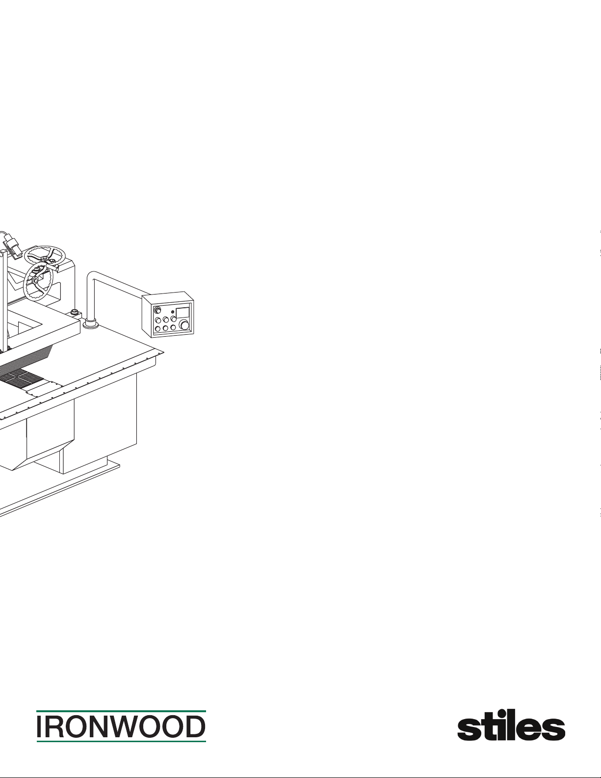
Pr
essure mechanism
Machine base
Front door
Saw arbor raising handwheel
Control panel
Pressure roller height
adjustment handwheel
Electrical contr
ol box
Rip fence
Front chain wheel guard
Laser device
1.5 Technical Specifications
Description Ironwood SLR330
Min Material Length 10" (250mm)
Material Thickness min 3
/
8" (10mm)
max 4" (100mm)
Distance Between Blade and Fence 18¾" (466mm)
Number of Hold-Down Rollers 8
Rows of Anti-Kickback Fingers 3
Working Table Height 32½" (850mm)
Saw Arbor Motor 15 hp
Saw Arbor Speed 4100 rpm
Saw Blade Diameter 10-12" (250-330mm)
Saw Arbor Diameter 1" (2.54mm)
Feed Speeds 16-131 fpm (5-40 m/min)
Feed Motor 1 hp
Table Area (w x l) 43" x 63" (1100mm x 1600mm)
Machine Dimensions (h x w x l) 97" x 45" x 55" (2469mm x 1150mm x 1403mm)
Net Weight 3200 lbs (1450 kg)
Dust Port Diameter 5" (125mm)
Dust Extraction Requirements 600 cfm @ 4,500 feet/min
Motor Power 230v (3-phase)
Amperage 40 amps
Shipping Dimensions (h x w x l) 68" x 45.3" x 70.9" (1720mm x 1150mm x 1800mm)
Shipping Weight 3370 lbs (1530 kg)

Ironwood SLR330 | User Manual 5
1.6 Safety Considerations
For your safety, read these instructions thoroughly before you install
and operate this machine. Always have these instructions available
at the machine for reference.
Observe all codes and regulations that apply to the installation and
operation of this machine.
Keep visitors at a safe distance from the work space.
Keep children away from this and all machines. Childproof your work
area!
Familiarize yourself with the safety notices used in this manual.
CAUTION
If cautions are ignored, personal injury and/or machine damage
may result.
WARNING
If warnings are ignored, serious injury or death may result.
Warning Labels
This machine has warning labels attached to ensure safe operation.
These warning labels are very important and should be kept clean
and never removed. If warning labels become damaged or lost,
contact Stiles Machinery immediately for replacements.
Label 1: Hazardous voltage label
Label 2: Danger, sharp saw blade
Label 3: Warning – Feed workpiece from this end
Label 4: Warning – do no stand in the cut line
Label 5: Safety instructions
Label 6: Notice – power will not start without the door closed
Label 7: Direction of saw rotation
Label 8: Warning – Entanglement hazard/pinchpoint
WARNING
Never use the SLR330 for purposes other than its intended use. Do
not modify or remove any guards or other safety features. Improper
use or modifications may affect your warranty or result in serious
injury or death.
Training
This machine is intended for use by authorized, well-trained
operators only.
Do not operate until you have a complete working knowledge of the
machine have been properly trained for its safe operation, correct
adjustment, and use. All operators should thoroughly read and
understand this manual and the workings of this machine prior to
operation.
It is essential that all operators be aware of the following:
• The dangers associated with the operation of this machine.
• The use of personal protective equipment for ear and eye
protection.
• The proper positioning of the operator and operator’s hands
relative to the saw blade.
• The principles of machine operation.
• The safe handling of the workpiece when cutting.
• The safe stacking of the workpiece before and after cutting.
LABEL NO. 1 LABEL NO. 2 LABEL NO. 3 LABEL NO. 4
LABEL NO. 5 LABEL NO. 6LABEL NO.
7L
ABEL NO. 8
NOTICE
The power will not be started
if you did not close the safety
door at first.
Direction of
saw’s revolution
SAFETY INSTRUCTIONS
1. Do not operate the machine until
all guards are in place.
2. Make sure the machine is properly
ground.
3. Do not wear loose clothes, neckties.
Pull up the long hair.
4. Remove all accessories such as
rings, watch and bracelets, etc.
5. Wear safety glasses and other
personal safety equipment.
6. Unplug electric power before
servicing.
7. Do not leave machine running
unattended.
8. Refer to instruction manual for
complete setup, operating and
servicing.
Feed Workpiece from
This End
WARNING

Ironwood SLR330 | User Manual6
2.0 Facility Preparation
Prior to uncrating your machine confirm that your location can
accommodate the Ironwood SLR330. Follow these guidelines:
2.1 Floor
• The floor must be flat and level.
• Although no special foundations are required, a concrete floor is
recommended.
• All floors must have a load-bearing strength suitable for the
machine weight of approximately 3,200 pounds (1,450 kg).
2.2 Work Space
• Provide adequate work space surrounding the machine.
• Provide proper non-glare, overhead lighting.
• Place the machine so that any potential kickback area is not in
line with aisles, doorways, or other work and traffic areas.
• Provide adequate dust extraction system.
The dust extraction system should have a flow rate with a speed
of 4,500 feet per minute at 600 cfm.
• Avoid exposure to any environment where vibration is present.
Standard machine clearance requirements
*
*
3'
(1000mm)
3'
(1000mm)
*
Machine clearance requirements*
*Actual clearance requirements may vary depending on length of
material to be cut.
2.3 Power
WARNING
A licensed electrician must connect the SLR330 to the building
power source.
• Do not use extension cords.
• Be sure that the electrical current of the power source is of the
same characteristics as the 230-volt electrical system supplied
with your machine. If other machine voltage capabilities are
required, contact Stiles Machinery.
SLR330
Saw Arbor Motor 15 hp, 230v, 60 hz
Feed Motor 1 hp, 230v, 60 hz
Amperage 40 amps
• Ensure the machine is protected with an external over-current
protective device per your local electrical codes.
• Electrical equipment operating conditions:
Air temperatures between +41ºF (+5ºC) and +113ºF (+45ºC).
Relative humidity not to exceed 50% at a maximum temperature
of +113ºF (+45ºC).
• Electrical equipment is designed and protected to withstand the
effects of transportation and storage temperatures within a range
of -13ºF (-25ºC) to +131ºF (+55ºC), and for short periods of time
not exceeding 24 hours at up to +158ºF (+70ºC).
• Ensure connection to factory ground system is wired correctly
(IAW local electrical codes and NEC) and not connected to any
electro magnetic interference source such as welders.

Ironwood SLR330 | User Manual 7
3.0 Delivery and Installation
3.1 Receiving Your Machine
You will be contacted to arrange delivery. Your machine will be
delivered by truck to your location. If there is no loading dock, be
sure that you have informed the carrier in advance so that they
deliver using a truck with a lift gate to lower the machine to
ground level.
Before accepting the machine and signing the bill of lading from the
carrier, please inspect crating and machine condition, note potential
damage on the bill of lading, take pictures of potential damage, and
contact Stiles Machinery immediately at 616.698.7500 and ask to
speak with the traffic department.
The machine will arrive fully crated and secured to a pallet. Use a
fork lift to move the machine on its pallet as close to its final position
as possible.
If you do not intend to install the Ironwood saw immediately after
delivery, store it in a protected, cool, and dry location.
The machine arrives fully
crated. Remove and save
the paperwork attached
to the outside.
3.2 Unpack the Machine
TOOLS REQUIRED:
• Hammer
• Crowbar
Unpack as follows:
Do not remove the machine from the pallet.
1. Remove and save all paperwork attached to the outside of the
crate.
2. Remove the crating, starting with the top, then remove the four
sides. Use caution to avoid personal injury and prevent damage
to the machine’s finish.
3. Remove the protective plastic from the machine, starting at the
bottom.
Remove the crating, starting
with the top, then remove
the four sides.
Do not remove the machine from the pallet while uncrating.

Ironwood SLR330 | User Manual8
3.3 Inspection
Save all containers and packing materials until you are satisfied
that your machine has arrived in good condition. If you discover the
machine is damaged after you’ve signed for delivery, immediately
call Stiles Customer Service at 616.698.7500.
When you are completely satisfied with the condition of your
equipment, you should inventory its parts.
Open and check the contents of all containers to ensure all tools,
hardware, and accessories are included. The tool kit should contain
the following items:
1. Oil pot
2. Open-ended wrench set (3 pieces)
3. Allen wrench set
4. 10mm T-handle Allen wrench
5. 4 leveling pads
6. 4 leveling bolts with nuts
7. Saw arbor wrench
8. Paint (2-color set)
9. Fence assembly
10. User manual
3.4 Move Machine to Final Position
Be sure the site is properly prepared. Refer to section 2.0 for details.
Be sure the access doors are closed and secured before
transporting.
TOOLS REQUIRED:
• Fork lift
Use a fork lift to move the machine on its pallet to its final location.
Make sure fork travel is clear of any obstacles or wiring. Lift the
machine from the front side so that the fork is positioned in the
fork slots in the machine base. When transporting the machine,
the fork must be over the center of gravity of the machine to avoid
hazardous situations.
The infeed and outfeed direction of workpieces must not face areas
where people gather or pass through.
Use a fork lift to move
the machine on its pallet.

Ironwood SLR330 | User Manual 9
3.5 Remove Machine from Pallet
CAUTION
The SLR330 weighs 3,200 pounds (1,450 kg). For this procedure,
we recommend using a fork lift.
TOOLS REQUIRED:
• Adjustable wrench
When the machine has been placed at its final location, carefully
remove the machine from the pallet.
The machine is
bolted to the pallet
for transport.
1. Remove the bolts securing the machine to the pallet at the
4 corners of the machine.
2. Lift the machine from the pallet with a forklift using the fork
holes located in machine base.
3. Carefully place the machine into final position.
Use a fork lift to move the
machine to its nal position.

Ironwood SLR330 | User Manual10
3.6 Level
TOOLS REQUIRED:
• Bubble Level
• Adjustable wrench
Use a bubble level along the length and width of the tabletop surface
to check for level. Use an adjustable wrench to adjust the 4 leveling
screws on the lower end of the machine to level machine. After
leveling, be sure to retighten the leveling screws.
Be sure to level
the machine
3.7 Pre-Operation Cleaning
WARNING
Use proper cleaning agents and methods described below. Do not
use gasoline or other petroleum-based solvents. There is a risk of
explosion and burning if these products are used. Serious personal
injury may occur.
Use a soft cloth and nonflammable degreasing agent, such as
Simple Green or other citrus-based cleaners to carefully clean off all
grease and rust preventative oils from all surfaces of the machine
and all lubricated parts. Do not use abrasive pads.
CAUTION
Use extreme care when cleaning the saw blade. It is very sharp.
Before installing the saw blade, clean its contact faces, saw arbor,
and lock washer with a clean cloth.
NOTE: Make sure the saw arbor flanges are completely clean when
installing the saw blade.

Ironwood SLR330 | User Manual 11
4.0 Connect to Power
• Voltage – Steady state voltage +/- 10% of nominal voltage.
• Machine needs steady voltage at all times.
WARNING
Before connecting power to the machine, make sure all screws and
fasteners are tightened, all mechanical functions work freely, and the
saw blade turns freely.
WARNING
A licensed electrician must complete all connections to electrical
power.
Before connecting to a power source, confirm that the electrical
current of the power source is the same as the electrical system
supplied with your machine. Ensure the machine is protected with
an external over current protective device per your local regulating
authorities.
Machine must be properly grounded to prevent electric shock.
Never connect the yellow/green wire to a live terminal.
Once connected to power source, terminals are under power even
while the power switch is off.
Proper wiring inside
terminal box
To connect power source to the machine:
1. Open the electrical cabinet
2. Place cable through electrical fitting on the bottom of the
cabinet.
3. Remove the clear plastic insulator that covers the main
incoming power terminals.
4. Insert source power cables through the opening of the terminal
box.
5. Connect the three power cables to terminals L1, L2 and L3,
and the yellow/green ground wire to ground terminal.
6. Replace the clear plastic insulator and close the electrical
cabinet
7. Tighten cable fitting on the bottom of the electrical cabinet to
properly secure incoming power cable.
WARNING
Always shut off power and lock out at source before opening
electrical cabinet. Failure to comply with this action may result in
electric shock.
CAUTION
We have covered some basic electrical requirements for the safe
installation of your machine. These requirements may not cover
all installation requirements. You must confirm that your particular
electrical configuration complies with all local codes. Ensure
compliance by checking with your local municipality and a licensed
electrician.

Ironwood SLR330 | User Manual12
5.0 Safety
WARNING
Like all power equipment, there is danger associated with the
Ironwood SLR330. Use caution and follow all safety instructions.
Take every precaution to protect yourself, others around you, and
the machine itself from improper use. Safety is a combination of
common sense, training, and being alert at all times while operating
your machine. If instructions, warnings, and cautions are not
followed, serious personal injury or death may occur.
EYE PROTECTION: Always wear approved safety glasses or a face
shield when operating this machine. Only use eye protection that
meets or exceeds the standards of the American National Standards
Institute (ANSI).
EAR PROTECTION: Always wear ear protection during machine
operation.
DRESS CODE: Do not wear loose clothing, neckties, jewelry, or
gloves that can get caught in moving parts. Confine long hair and
keep sleeves above the elbow.
ELECTRICAL GROUNDING: Your machine must be electrically
grounded. If a cord and plug are used, make certain the machine is
properly grounded. Follow the grounding procedure indicated by the
National Electric Code and local regulating authorities.
GUARDS: Make certain that machine guards are in place and in
good working order. The machine should never be operated without
the safety guards in place.
TOOLING AND ACCESSORIES: Use only recommended tooling
and accessories. Improper tooling and accessories may cause
personal injury or damage to your machine. Always run at the
correct speed and feed rate. Regularly maintain your tools and
accessories. The saw blade should be sharpened and cleaned for
safe, optimal performance. Follow instructions for lubricating and
changing tooling and accessories.
POWER: Make sure the starter is in the OFF position before
connecting power to the machine.
Make certain the machine is either unplugged or electrically
disconnected and locked out when performing all maintenance,
cleaning, or machine adjustments. Never leave the machine running
unattended. Always turn the power off and stay by the machine until
the saw blade comes to a complete stop.
HOUSEKEEPING: Before turning the machine on, remove all extra
items on or around the machine. Keep the work area clean and free
of scrap material, sawdust, and other debris to minimize the danger
of slipping. Use compressed air or a brush to remove chips or
debris. NEVER use your hands.

Ironwood SLR330 | User Manual 13
6.0 Assembly
6.1 Install Saw Blade
PARTS REQUIRED: TOOLS REQUIRED:
• Saw blade • Saw arbor wrench
• Open-ended wrench
Before installing the saw blade, make sure the diameter of the saw
blade is correct. Refer to the drawing below:
D=254mm (10")
305mm (12")
ø25.4
ø D
1. Loosen the saw arbor locking lever.
2. Open the blade access door.
Saw arbor lock lever
3. Raise the saw arbor by turning the saw arbor handwheel
so there is ample room for installing the saw blade without
touching the feed chain.
4. Loosen the wing nuts on the small pressure rollers and move
them away from the saw blade position.
5. Open the rear door and fit the supplied saw arbor wrench into
the cross slot on the pulley for securing the saw arbor.
Saw arbor wr
ench
6. Loosen the hex bolt securing the lock washer/hub and remove
the hub.
7. Mount the saw blade with the teeth pointing in the same
direction as the rotation of the arbor (counterclockwise).
CORRECT WRONG
Handwheel
8. Reinstall the lock washer/hub, securing with the supplied
hex bolt.
NOTE: Ensure the saw blade and hub are clean and free of any oil or
debris before installing the saw blade.

Ironwood SLR330 | User Manual14
9. Tighten the hex bolt to secure the saw blade.
T
ighten hex bolt
Saw blade
Chain block
10. Adjust the small pressure rollers to provide support for the
workpiece near the saw blade and secure with wing nuts.
11. Lower the arbor until the saw blade teeth are below the feed
chain by 0.5-1.5mm. Ensure the teeth do not touch the feed
chain. The rubber inserts in the center of the feed chain allow
saw blade depth below the surface of the feed chain.
Chain block
Rubber insert
12. Lock the saw arbor locking lever.
13. Close the blade access door and secure.
14. Remove the saw arbor wrench from the cross slot of the pulley
and close the rear access door.
Release
Lock
raise saw ar bor
lower saw arbor
To remove the saw blade:
1. Loosen the saw arbor locking lever.
2. Open the blade access door.
3. Raise the saw arbor by turning the saw arbor handwheel so the
saw blade teeth are 5-10mm higher than the feed chain.
4. Loosen the wing nuts on the small pressure rollers and move
them away from the saw blade position.
5. Open the rear door and fit the supplied saw arbor wrench into
the cross slot on the pulley for securing the saw arbor.
6. Loosen the hex bolt securing the lock washer/hub and blade.
7. Remove the saw blade.
6.2 Attach Rip Fence Assembly
The rip fence assembly attaches to the front of the machine. Use the
rip fence to position and guide the workpiece as you feed it into the
machine. The top of the rip fence assembly bracket has a measuring
scale that indicates the width of the cut (distance between fence and
saw blade).
To mount the rip fence assembly:
1. Hold the assembly up to the front of machine and align it with
the predrilled holes.
2. Tighten with the supplied bolts.
3. Check the fence for squareness to the saw blade and adjust as
shown below:
Adjustment handle
Lock
Rip fence
assembl
y
Linear
guideway
Release
To lock the rip fence in place, push the handle away from you. To
release it, pull the handle toward you.
The rip fence should glide easily on the linear guideway for quick and
easy ripping width adjustment.

Ironwood SLR330 | User Manual 15
6.3 Connect Dust Collection System
The dust collection outlet is 5" (125mm) in diameter. Connect the
flexible tube of a suitable dust extraction system to the outlet. The
dust extraction system should have a flow rate of 4,500 feet/min at
600 cfm.
NOTE: Flex hose length should not exceed 30 feet or suction
velocity will decrease, causing inadequate dust collection.
Dust collection outlet
The dust collection outlet is located in the top of the machine.

Ironwood SLR330 | User Manual16
7.0 Operation and Adjustments
WARNING
Do not attempt to operate machine if you are not completely familiar
with its operation. Obtain immediate advice from a supervisor,
instructor, or other qualified personnel.
Use of this machine requires that you give your work your undivided
attention, and careless acts or not paying close attention to work
being performed may result in serious injury to yourself and/or
others. Never operate this or any machine under the influence of
drugs, alcohol, or any medication that may impair judgment.
Dust created by manufacturing activities may be harmful to your
health.
Your risks from exposure may vary. Always work in a well-ventilated
area and wear safety approved, protective dust masks specifically
designed to filter out microscopic particles. Utilize wood dust
collection systems appropriate to your machine type.
Avoid Kickback
It is very important that each workpiece be carefully inspected
for stock condition and grain orientation before running through
the machine. Kickback can result when the workpiece has knots,
holes, or foreign materials such as nails. It can also occur when the
material is fed against the grain.
7.1 Machine Controls
1
1. Amp meter for saw motor
10469
23578
2. Power indicator lamp
3. Power sour
ce start button
4. Power sour
ce stop button
5. Saw blade start button
6. Saw blade stop button
7. Feed chain conveyor speed knob
8. Feed chain start button
9. Feed chain stop button
10. Emergency stop
Machine controls are conveniently located at eye level on a pivoting arm.
7.2 Machine Operation
Step 1: Adjust Pressure Roller Assembly Height
WARNING
Pressure rollers must be adjusted to the proper position to prevent
kickback.
There are 4 pressure rollers on each side of the saw blade to hold
down the workpiece during the cut. Adjust the height of the pressure
roller assembly according to workpiece thickness.
Rollers
Pressure ro
ller
locking lever
An adjustment example is shown above.
1. Release the pressure roller locking lever.
2. Pressure roller height is indicated on the scale on the front of
the pressure roller assembly housing. The thickness of the
workpiece should be set using the indicator scale. The pressure
rollers are 2mm lower than the indicator scale to ensure the
correct amount of pressure is applied to the workpiece. When
cutting a thicker workpiece, the indicator scale can be adjusted
2-4mm less than the workpiece thickness to increase pressure.
3. Tighten the pressure roller locking lever to secure the pressure
rollers before running the saw.

Ironwood SLR330 | User Manual 17
Step 2: Adjust Rip Fence
Rip fence position
1. Pull the handle toward you to release the fence.
2. Hold up the anti-kickback fingers using the handle.
3. Move the fence assembly along the measuring guide to set the
width of cut (distance between the saw blade and fence).
4. Push the handle away from you to lock the fence in position for
your cut.
5. Release the anti-kickback finger handle to allow the fingers
to drop.
Rip fence squareness
Adjust rip fence squareness on the bottom of the rip fence assembly.
Adjustment depends on which direction the rip fence is out of
alignment. For example, in the case of fig. 1 below:
1. Loosen screws A, B, and C.
2. Loosen lock nut B2, and turn B3 to the right.
3. Loosen lock nut A2, and turn A3 to the right.
4. Check for squareness.
5. Tighten the lock nuts and securing screws to fix the rip fence in
the correct position.
B3
A2
A3
BA
DC
B2
Step 3: Check Anti-Kickback Fingers
There are three rows of auto-adjust anti-kickback fingers. The anti-
kickback fingers do not need to be adjusted.
For safety, be sure the top anti-kickback fingers hang down in a row,
point in the direction of the feed chain, and can be lifted smoothly.
Be sure the bottom anti-kickback fingers press down and lift up
smoothly.
Step 4: Start the Saw Blade
WARNING
Before starting the machine, inspect it to ensure it is free of all
debris. Remove wood chips and sawdust only with the power OFF.
Make certain that the saw blade is installed with the teeth pointing in
the same direction as the rotation of the saw arbor.
Never start the machine with the workpiece in contact with the saw
blade.
Make sure the workpiece is free of nails, loose knots, and other
defects that could cause personal injury or damage the saw blade.
Press the saw blade start button. Make sure the power-on indicator
lights up.
Power indicator light
Start button
When starting machine for the first time, blade rotation must be
checked. If blade rotation is not the same direction as the arrow
indicates (against the feed), phasing must be changed.
To re-phase machine:
1. Disconnect the main power supply.
2. Open the electrical cabinet and test power leads to ensure
power is off.
3. Switch two of the power legs (e.g., L1 and L2).
4. Close the electrical cabinet.
5. Activate power to the machine.
6. Test rotation again.

Ironwood SLR330 | User Manual18
Step 5: Start and Adjust the Feed Chain
Press the feed chain start button.
Feed chain start button
Adjust the feed speed according to the thickness and type of wood
being cut. The range of feed speed is 16-131 ft/min (5-40m/min).
The optimal feed speed varies depending on the material being cut
and the cut quality desired.
Increase speed by turning clockwise; decrease by turning
counterclockwise.
Step 6: Activate the Laser Cutline Guide
To ensure cutting accuracy the entire length of the workpiece, use
the laser cutline guide.
To activate, plug in the laser on the right side of anti-kickback finger
support arm.
The laser should accurately indicate the cut line path. If the laser line
does not align with the cut line, use the adjustment screws located
on the laser bracket to align.
ADJUSTMENT TIP: Mark the laser line on the board before cutting
for reference after the board is cut.
Step 7: Make Your Cut
WARNING
If you are inexperienced at rip sawing, become familiar with the
machine and its operation before doing normal work. Use scrap
pieces of lumber that are not warped, bowed, or too small.
Stand to the side of the workpiece when feeding it through the saw
to avoid potential injury from kickback and loose chips.
Keep your hands away from the saw blade area.
To stop a workpiece before it is entirely fed through the machine,
press OFF. Wait until the saw blade has completely stopped before
removing material. Attempted removal while saw blade is turning
may cause kickback.
The four sides of the workpiece should be even in thickness to
obtain a precise straight-line rip, Thickness should not exceed
4" (400mm). The workpiece should not be curved, warped, or
deformed.
The workpiece should be at least 10" (250mm) long to ensure the
pressure rollers hold the workpiece properly for a high-quality cut.
Stand at the side of the machine. Never stand behind the ripping
line. The danger zone includes an angle of 30 degrees on both sides
of the ripping line.
Always wear leather gloves, a leather apron, and a face shield.
Place the workpiece on the worktable against the fence and feed it
between the feed chain and pressure rollers to begin sawing.
WARNING
The operator MUST let go of the workpiece as soon as it has been
pushed into the machine. If the workpiece does not enter into the
machine properly, the operator should NEVER attempt to straighten
it with his/her hands.
After the cut, check the profiles of the workpiece to verify that the
cut quality is acceptable and that the feed speed is correct. Adjust
the feed speed if necessary (see Step 5).
WARNING
Never leave the machine unattended while in use. After switching
off the machine, be certain to wait until the saw blade comes to a
complete stop before walking away.
7.3 Rip Sawing Tips
When the edges of a workpiece are not square, the wider side
should always face down on the feed chain. The wider portion
will maintain more surface area on the feed chain for maximum
accuracy.
Pressure roller
CORRECT WRONG

Ironwood SLR330 | User Manual 19
When a workpiece is warped transverse, the convex side should
face down on the feed chain. If the convex side faces up, the saw
blade might become clamped by the workpiece, causing kickback.
Pressure roller
CORRECT WRONG
When a workpiece is warped lengthwise, the convex side should
face up on the feed chain. If the convex side faces down, the
pressure rollers will not work smoothly, which can affect accuracy.
CORRECT WRONG
7.4 Adjust Oil Supply to Feed Chain
The central lubrication system automatically applies oil at specific
intervals. The intervals can be adjusted according to conditions.
If the oil in the tank is below the minimum allowed value, the feed
chain will stop running automatically to prevent damage.
Oil flows from the central lubrication system to the oil distributor,
which then distributes oil to various points. The image below shows
the lubrication points and which line lubricates which point.
Brush (2)
Brush (3
)
Chain rail (1)
Chain rail (2)
Brush (1)
Brush (1)
Brush (2)
Brush (3
)
Chain rail (1
)
Chain rail (2
)
Oil distributor
Check every day before machine operation to ensure the oil reservoir
is full.
Before starting the machine, press the manual lubrication button
located on the front of the lubricator for 10-15 seconds to start the
flow of oil to the lubrication points. When starting the machine, make
sure the lubricator is in the intermittent OFF position to avoid over
lubrication due to repetitive starting.
NOTE: The oil pump in the central lubrication device is not intended
for continuous pumping for an extended time. Pressing the manual
lubrication button for more than 3 minutes may damage the oil
pump motor.
Oil inlet
Oil level
gauge

Ironwood SLR330 | User Manual20
The machine comes preset at the factory to provide 10 seconds of
active lubrication time and 20 minutes of intermittent time between
pumping cycles. These intervals can be adjusted based upon actual
operating conditions.
To manually set automatic lubrication time intervals:
1. Open the control box cover on the top of the central lubrication
device.
2. Select active lubrication time. You can choose 5, 10, 15, or
20 seconds of active pumping time. The label on the control
box cover shows how to set the pumping time for the various
time interval choices.
3. Select intermittent time. You can choose 3, 15, 20, or 30 minute
intervals between pumping cycles.
4. Close the control box cover.
CESPWIRING DIAGRAM
POWER GROUNDABNORMALOUTPUT
POWERGND
(PE)COM (B)
NC
(A)
NO
ACT.TIMEKEYINT.TIMEKEY
RED/LEFT BLUE/RIGHT
CONDITIONACT.TIMECONDITION ACT.TIME
5sec
10sec
15sec
20sec
3min
15min
20min
30min
10 0
1
00 0
10 1
0
10
0
11
Act. time key
Int. time key
Manual pumping
switch
CESP WIRING DIAGRAM
POWERGROUNDABNORMAL OUTPUT
POWER GND
(PE) COM (B)
NC
(A)
NO
ACT. TIME KEYINT. TIME KEY
RED/LEFT BLUE/RIGHT
CONDITIONACT. TIME CONDITIONACT. TIME
5 sec
10 sec
15 sec
20 sec
3 min
15 min
20 min
30 min
100
101
010
011
000
101
010
011
7.5 Adjust Hold-Down Pressure for Pressure Rollers
Hold-down pressure is adjustable to accommodate the cutting
application. To adjust:
1. Locate the adjustment points for the rollers you wish to adjust.
The adjustment points are located on the top of the pressure
roller assembly housing. To adjust the split pressure rollers
located closest to the blade, open the blade access door.
2. Loosen the lock nut on the adjustment screw.
3. Turn the adjustment screw clockwise to increase pressure on
the pressure roller. Turn counterclockwise to decrease pressure.
4. Tighten the lock nut.
5. Close the blade access door if opened.
Adjustment points
Adjustment points
Table of contents
Other Stiles Saw manuals