STILLA Birch 6x3 User manual

STILLA
ASSEMBLY INSTRUCTIONS
‘Birch’6x3
S3001
Every part needed to construct your shed is included inside the pack; cedar
panels, doors, windows, hardware kits & roof sheeting. Please ensure you fully
unpack all the parts & check against the parts checklist before contacting
customer service about anything you believe may be missing. Thank-you!
Caution

1 | P a g e
Please be careful when handling all components, some parts have sharp metal edges.
Always wear work gloves, eye protection and long sleeves when assembling or maintaining
your shed.
Tools required for assembly
•Level
•Drill
•Hammer
•Ladder
•Phillips head drive
•Hex Head Drive (5/16’)
•Safety glasses
•Gloves
Before assembly
•Remove all parts from packages and place in a safe place close to assembly area.
•Review all instructions; continue to refer to instructions throughout assembly –step
by step.
Preparing your site
•Choose your site carefully, site surface must be level (unless an Elevation kit or
Heavy duty floor kit option has been purchased with your product)
2 | P a g e
BIRCH 6x3 PARTS CHECKLIST
Part Code
Checked
Part Description
Qty
P
Cedar Clad Panel 900x1890mm
2
LP
Tapered Panel (Left) 900x1875mm
1
RP
Tapered Panel (Right) 900x1875mm
1
FP
Cedar Clad Front Panel 195x1805mm
2
D
6x3 Door 700x1770mm (Full Cedar)
2
C
1970mm Channel
1
L
1970mm L Flashing –ZINC
1
L
1040mm L Flashing –ZINC
2
RS
1040mm Roof Sheeting
3
HK
6x3 Hardware Kit
1
CP
Corner Post 2x1805 2x1890
4
CS
Cover Strip 1890x40x7mm
1
DS
Door Step 1410x42x19mm
1
DH
6x3 Door Head 1800mm
1
IM
6x3 Instruction Manual
1
Floor Kit –Option
Floor Frame - (Rebated Floor 70x35mm/Heavy Duty Floor 140x35mm)
Part Code
Checked
Part Description
Qty
EP
End Plate 1870mm
2
DJ
Double Joist 830mm
2
SJ
Single Joist 830mm
3
L
Logs (light duty floor does not come with logs)
4
FB
1798mm x 485mm
1
FB
1798mm x 326mm
1
3 | P a g e
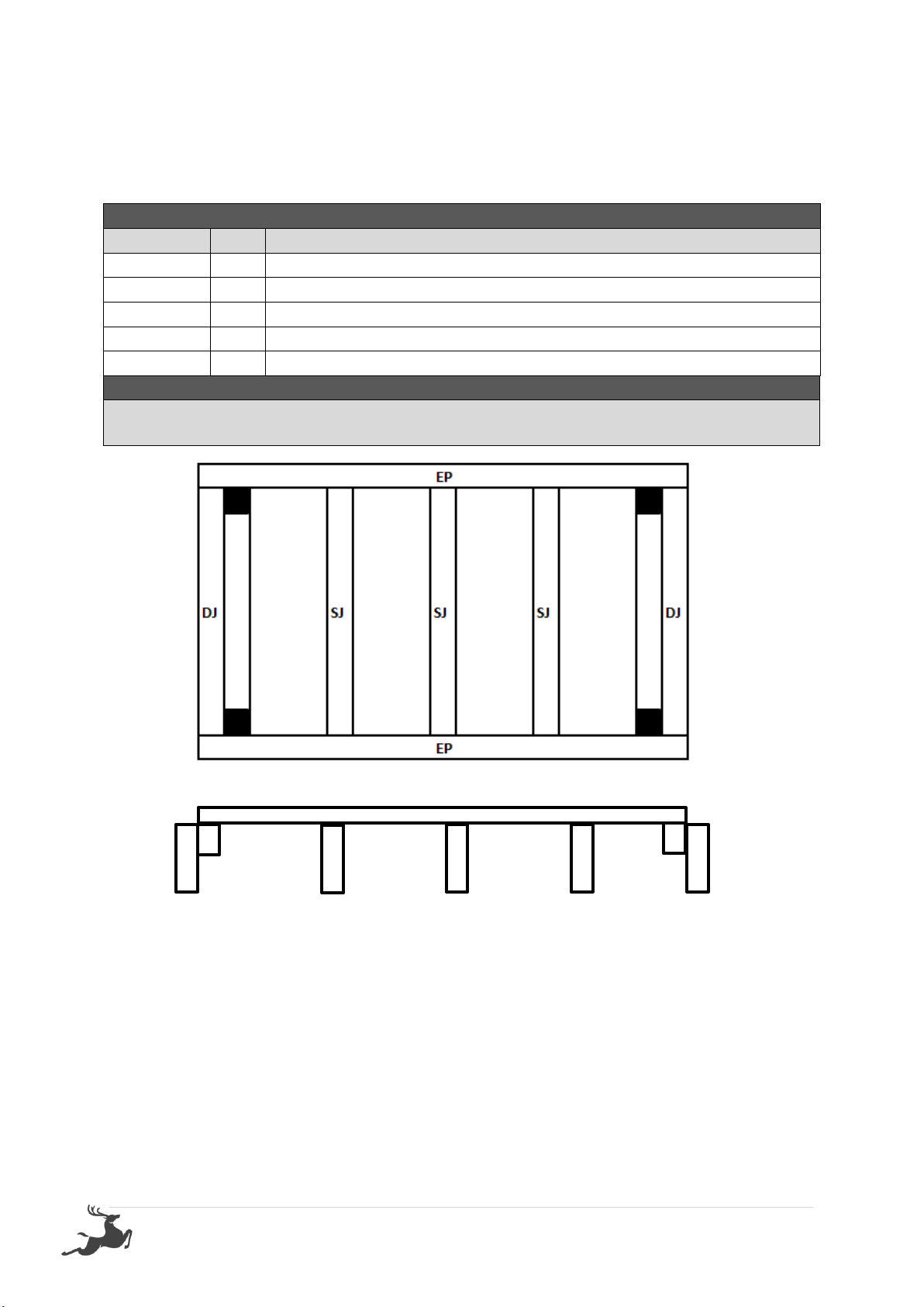
If no floor option was purchased, go to step 2.0 (Wall Assembly)
STEP 1.0
FLOOR KIT
1.0 –FLOOR KIT
PART CODE
QTY
DESCRIPTION
EP
2
End Plate 1870mm
SJ
3
Single Joist 830mm
DJ
2
Double joist 830mm (42x35mm part of DJ goes at the top inside)
100BS
24
100mm Batten screw (Heavy Duty Floor Only)
75N
24
75mm Nail (Rebated Floor Only)
1.0 –FLOOR FRAME
Fasten through EP into DJ using 3 x 100BS per join (75N on Rebated Floor)
Fasten Through EP into SJ using 2 x 100BS per join (75N on Rebated Floor)
HEAVY DUTY FLOOR KIT
Heavy duty floor can be installed on unlevelled ground –use supplied logs to level your floor
by digging them into the ground.
Install heavy duty floor kit using 4 logs –1 in each corner (position shown above) screw
through frame into log using 4 x 100BS per corner.
Ensure floor frame is square by measuring from corner to corner diagonally prior to
installing flooring.
Yellow Tongue
DJ
DJ
SJ
SJ
SJ

4 | P a g e
STEP 1.1
FLOORING INSTALLATION
1.1 –FLOOR INSTALLATION
PART CODE
QTY
DESCRIPTION
FB
1
Floor Board 1798x485mm
FB
1
Floor Board 1798x326mm
50PS
20
50mm Phillips Screw
1.1 –FLOOR SHEETS
Fasten floor sheet to floor frame as shown below using 50PS
5 | P a g e
STEP 2.0
WALL ASSEMBLY
2.0 - ASSEMBLY PARTS –WALL ASSEMBLY
PART CODE
QTY
DESCRIPTION
FP
1
Front panel
LP
1
Tapered panel left
65HHS
3
65mm hex head screw
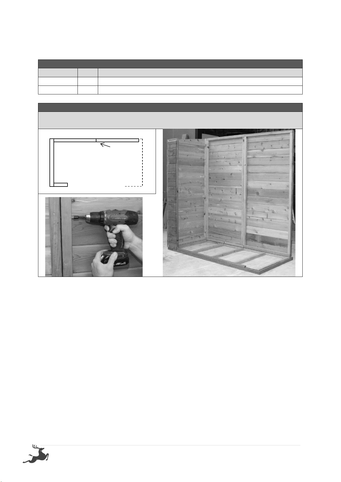
2.0 - ASSEMBLY –WALL ASSEMBLY
Screw through FP into LP (top, centre & bottom) using 3 x 65HHS. (Holding studs flush on
the outside)Note –ensure tongue of cedar cladding is at the top on all panels.
LP
Screw 3 x 65HHS (Top,
centre & bottom)
FP
6 | P a g e
STEP 2.1
WALL ASSEMBLY
2.1 - ASSEMBLY PARTS –WALL ASSEMBLY
PART CODE
QTY
DESCRIPTION
P
1
900mm panel
65HHS
3
65mm hex head screw
2.1 - ASSEMBLY –WALL ASSEMBLY
Screw through P into LP (Top, centre & bottom) using 3 x 65HHS, holding studs flush on the
outside.
P
LP
Screw 3 x 65HHS (Top,
centre & bottom)
7 | P a g e
STEP 2.2
WALL ASSEMBLY
2.2 - ASSEMBLY PARTS –WALL ASSEMBLY
PART CODE
QTY
DESCRIPTION
P
1
900mm panel
65HHS
3
65mm hex head screw
2.2 - ASSEMBLY –WALL ASSEMBLY
Screw through P into P (Top, centre & bottom) using 3 x 65HHS, holding studs flush on the
inside.
P
Screw 3 x 65HHS (Top,
centre & bottom)
P

8 | P a g e
STEP 2.3
WALL ASSEMBLY
2.3 - ASSEMBLY PARTS –WALL ASSEMBLY
PART CODE
QTY
DESCRIPTION
RP
1
Tapered panel right
65HHS
3
65mm hex head screw
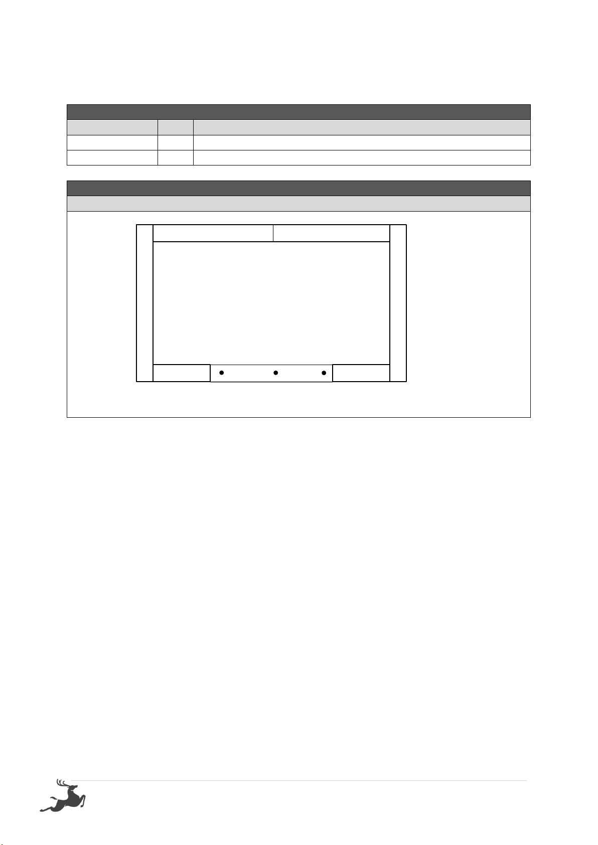
2.3 - ASSEMBLY –WALL ASSEMBLY
Screw through P into RP (top, centre & bottom) using 3 x 65HHS holding studs flush on the
outside.
STEP 2.4
WALL ASSEMBLY
2.4 - ASSEMBLY PARTS –WALL ASSEMBLY
PART CODE
QTY
DESCRIPTION
FP
1
Front panel
65HHS
3
65mm hex head screw
2.4 - ASSEMBLY –WALL ASSEMBLY
Screw through FP into RP (top, centre & bottom) using 3 x 65HHS holding studs flush on the
outside.
P
Screw 3 x 65HHS (Top,
centre & bottom)
P
RP
P
Screw 3 x 65HHS
(Top, centre &
bottom)
P
FP
RP
9 | P a g e
STEP 2.5
DOOR STEP INSTALLATION
2.5 - ASSEMBLY PARTS –DOOR INSTALLATION
PART CODE
QTY
DESCRIPTION
DS
1
Door Step
40N
3
40mm Nail
2.5 - ASSEMBLY –DOOR INSTALLATION
Nail through DS into floor frame (if floor option was not chosen fasteners are not supplied)
DS
10 | P a g e
STEP 2.6
FASTENING WALLS TO FLOOR
2.6 - ASSEMBLY PARTS –FASTENING WALLS TO FLOOR
PART CODE
QTY
DESCRIPTION
65HHS
7
65mm hex head screw
2.6 - ASSEMBLY –FASTENING WALLS TO FLOOR
Ensure walls are in correct position and straight.
Fasten through wall bottom plate in positions shown below.
If floor option not chosen, fasteners are not supplied.
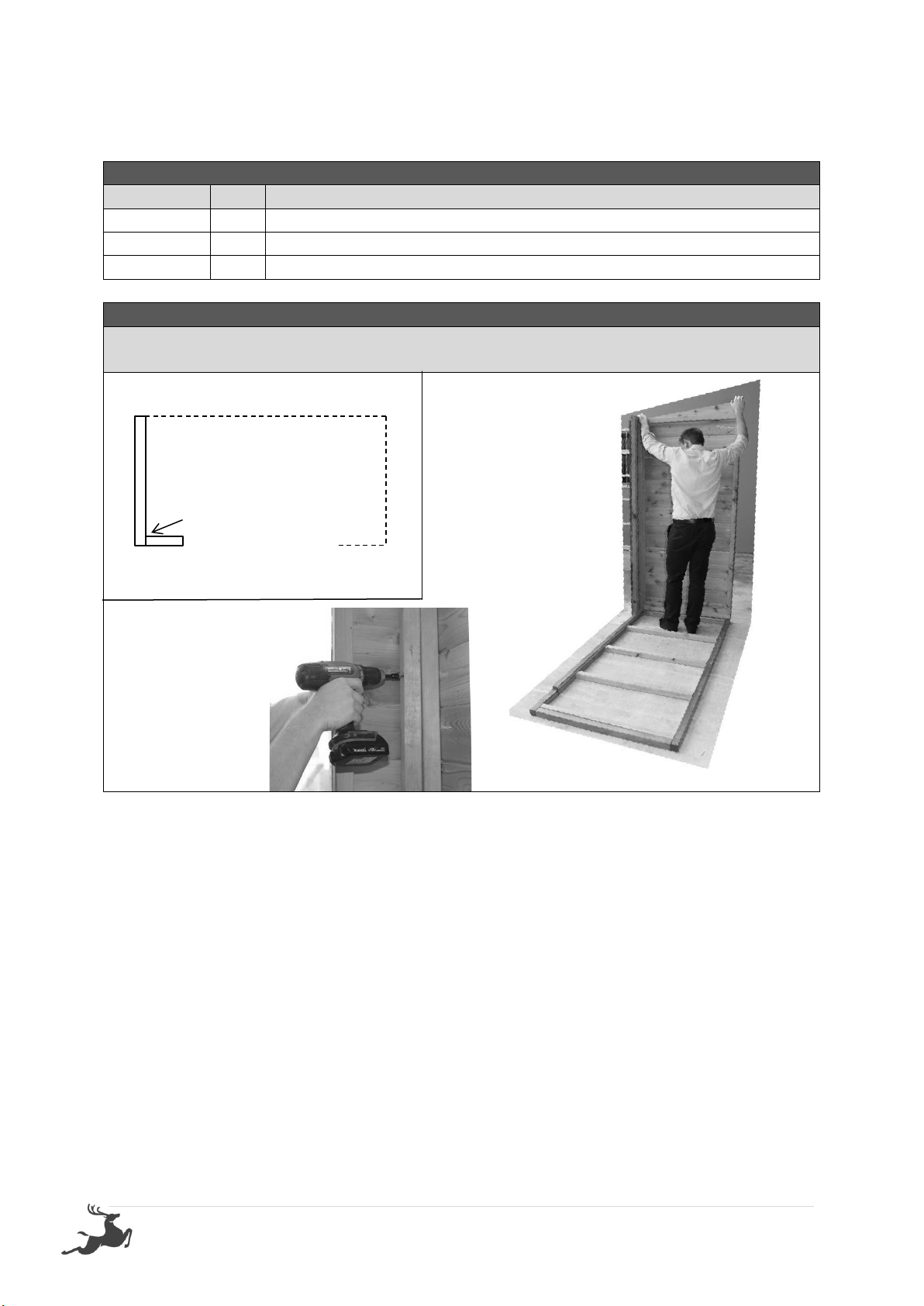
STEP 3.0
ROOF ASSEMBLY
3.0 - ASSEMBLY PARTS –ROOF ASSEMBLY
PART CODE
QTY
DESCRIPTION
RS
3
1040mm roof sheet
3.0 - ASSEMBLY –ROOF ASSEMBLY
Lay RS x 3 down on a flat hard surface and overlap until full measurement is 1970mm.
Bent up edge goes at the back of the shed.

11 | P a g e
STEP 3.1
ROOF ASSEMBLY
3.1 - ASSEMBLY PARTS –ROOF ASSEMBLY
PART CODE
QTY
DESCRIPTION
L
1
1970mm L flashing
C
1
1970mm C channel
ST
8
Self-tapping screw
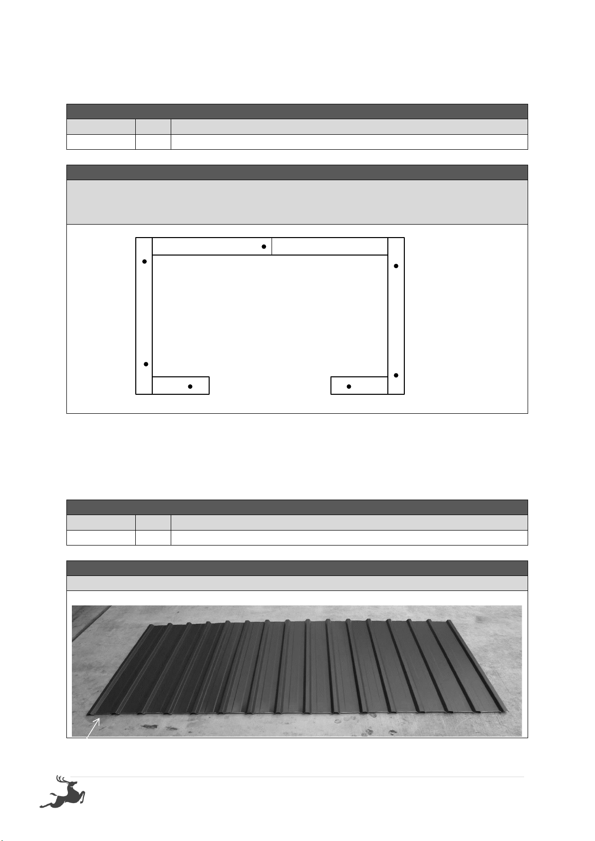
3.1 - ASSEMBLY –ROOF ASSEMBLY
Place L on RS (Roof Sheets) as shown in picture. Screw through top, 1 Rib in from each end
and into each join of sheet (4 times all up) using ST x 4.
Slide C into place and repeat process.
Screw
Screw
Back
Front
Bent up edge
L
C

12 | P a g e
STEP 3.2
ROOF ASSEMBLY
3.2 - ASSEMBLY PARTS –ROOF ASSEMBLY
PART CODE
QTY
DESCRIPTION
L
2
1040mm L flashing
ST
6
Self-tapping screw
3.2 - ASSEMBLY –ROOF ASSEMBLY
Place L into position, as shown in picture. Screw through L into L at back and 1970C at front.
Screw threw L into roof sheet (RS) in centre. (repeat at both ends of the roof)
STEP 3.3
DOOR HEAD ASSEMBLY
3.3 - ASSEMBLY PARTS –DOOR HEAD ASSEMBLY
PART CODE
QTY
DESCRIPTION
DH
1
Door head
40N
4
40mm Nail
3.3 - ASSEMBLY –DOOR HEAP ASSEMBLY
Place DH in position and fasten through DH into FP using 2 x 40N at each end.
Screw
Screw
(Note: This drawing does not show the right number of ribs)
L
L

13 | P a g e
STEP 3.4
ROOF INSTALLATION
3.4 - ASSEMBLY PARTS –ROOF INSTALLATION
PART CODE
QTY
DESCRIPTION
1
Assembled Roof
40RS
24
40mm Roof screw
3.4 - ASSEMBLY –ROOF INSTALLATION
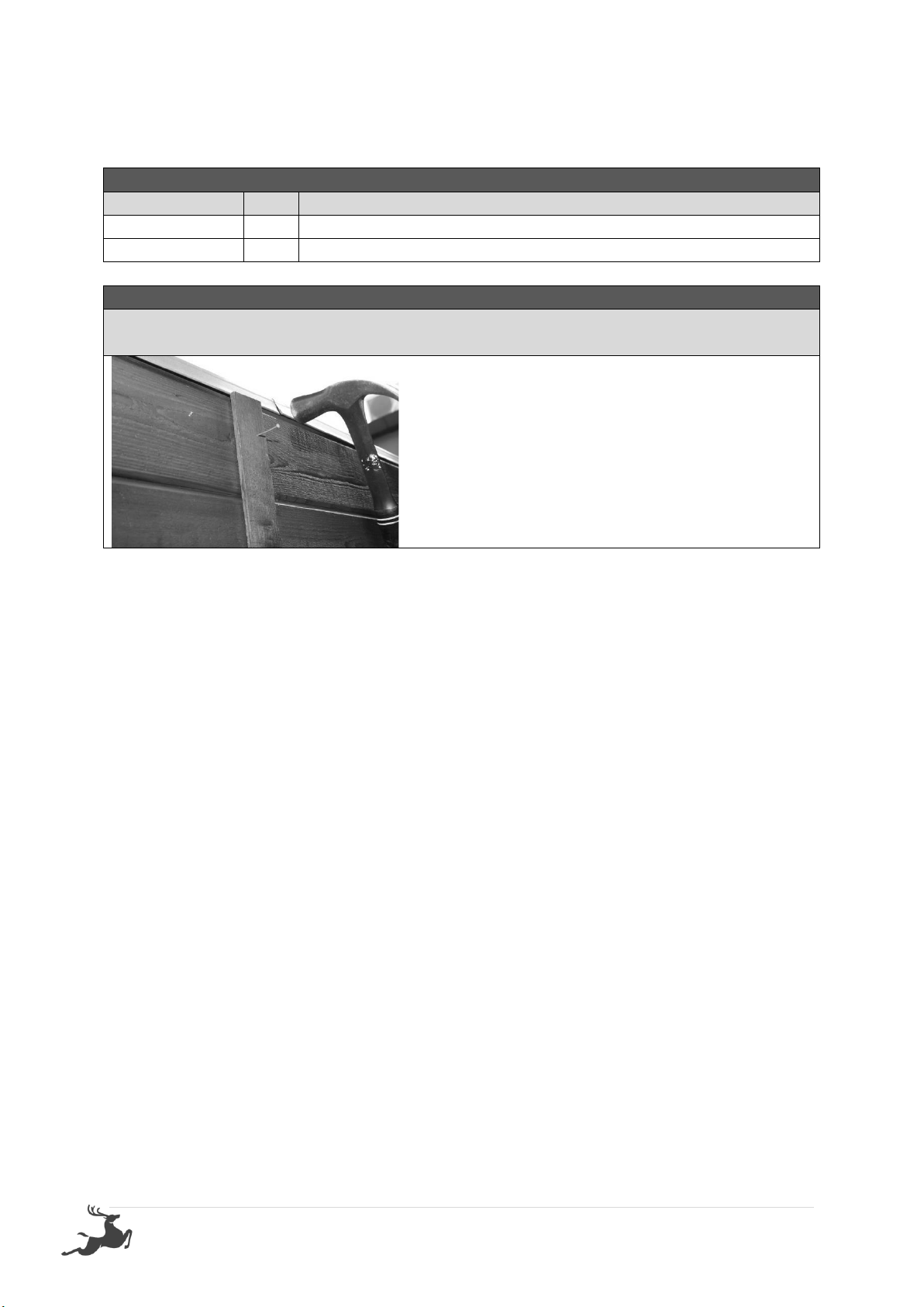
Slide roof into position with L at back. Roof must hang over back walls by 20mm and even
hangover on side walls. Screw through roofing rib into top plate of front and back wall
panels starting in four corners on 2nd rib in.
Note: Use a straight edge to keep screws in line.
STEP 3.5
DOOR HINGE ASSEMBLY
3.5 - ASSEMBLY PARTS –DOOR HINGE ASSEMBLY
PART CODE
QTY
DESCRIPTION
H
4
Hinge
HS
12
Hinge Screw
D
2
Door
3.5 - ASSEMBLY –DOOR HINGE ASSEMBLY
Place door on back and hold hinge (H) in position. Fasten hinges to door using 3 x hinge
screws (HS) per hinge –Predrilling these screws is recommended.
Position: Hinges are to be placed at top and bottom of door. They are to be centralised over
bracing on back of door (as per second and third image below)

14 | P a g e
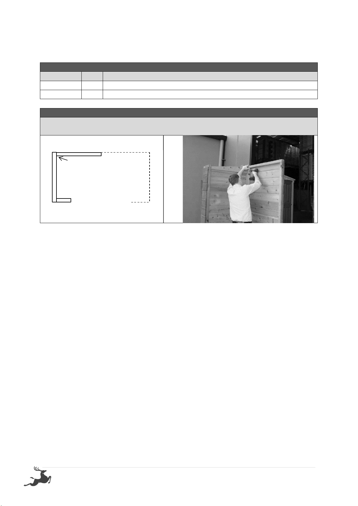
STEP 3.6
DOOR INSTALLATION
3.6 - ASSEMBLY PARTS –DOOR INSTALLATION
PART CODE
QTY
DESCRIPTION
D
2
Door
HS
12
Hinge screw
3.6 - ASSEMBLY –DOOR INSTALLATION
Hold door in position, 3mm down from top. Front of the door when closed will be flush with
front of VJ cladding- Predrilling is recommended.
Screw through hinge into front wall (as pictured).
STEP 3.7
PAD BOLT INSALLATION
3.7 - ASSEMBLY PARTS –PAD BOLT INSTALLATION
PART CODE
QTY
DESCRIPTION
PB
2
Pad bolt
3.7 - ASSEMBLY –PAD BOLT INSTALLATION
Hold PB in position and fasten to door. Mark centre of bolt (while closed) and drill 12mm
hole in marked position. Repeat for bottom pad bolt- Fasten Padbolts to Door

15 | P a g e
STEP 3.8
PAD BOLT INSALLATION
STEP 4.0
CORNER POSTS
4.0 - ASSEMBLY PARTS –CORNER POSTS
PART CODE
QTY
DESCRIPTION
CP
4
2 x 1890 –2 x 1805
40N
24
40mm Nail
4.0 - ASSEMBLY –CORNER POSTS
Hold CP in position nail through corner post into wall stud. (6 x 40N per corner) Repeat on
all corners using1890mm at back and 1805 mm at front.
3.8 - ASSEMBLY PARTS –PAD BOLT INSTALLATION
PART CODE
QTY
DESCRIPTION
PB
1
Pad bolt (fasten to door that is not pad bolted inside)
3.8 - ASSEMBLY –PAD BOLT INSTALLATION
Holding doors in closed position. Hold PB centre of the door as shown in picture. Screw
through PB into door. Hold clasp in position and fasten to door.
16 | P a g e
STEP 4.1
COVER STRIPS
4.1 - ASSEMBLY PARTS –COVER STRIPS
PART CODE
QTY
DESCRIPTION
CS
1
Cover strip
40N
6
40mm Nail
4.1 - ASSEMBLY –COVER STRIPS
Hold CS in position, covering join on back wall.
Using 6 x 40N, nail in position.

17 | P a g e
TO REGISTER YOUR WARRANTY
Thank-you for purchasing a STILLA product. To register your 10 year product
warranty, please go to www.stilla.com.au/warranty and complete the online
form. We recommend that you complete this step once you have finished
installing your product.
PLEASE NOTE THAT IF YOU DO NOT COMPLETE THIS WARRANTY
REGISTRATION FORM –YOUR PRODUCT IS NOT COVERED BY WARRANTY.
PRODUCT MAINTENANCE
We highly recommend you coat the external of your product with Intergrain
Stain –Light Oak. This product cannot be bought off the shelf but is a known
mix of Ultra Deck Intergrain Cedar/Cypress and a black paint. This can be
purchased from Dulux paint store or the paint section at Bunnings.

18 | P a g e
19 | P a g e
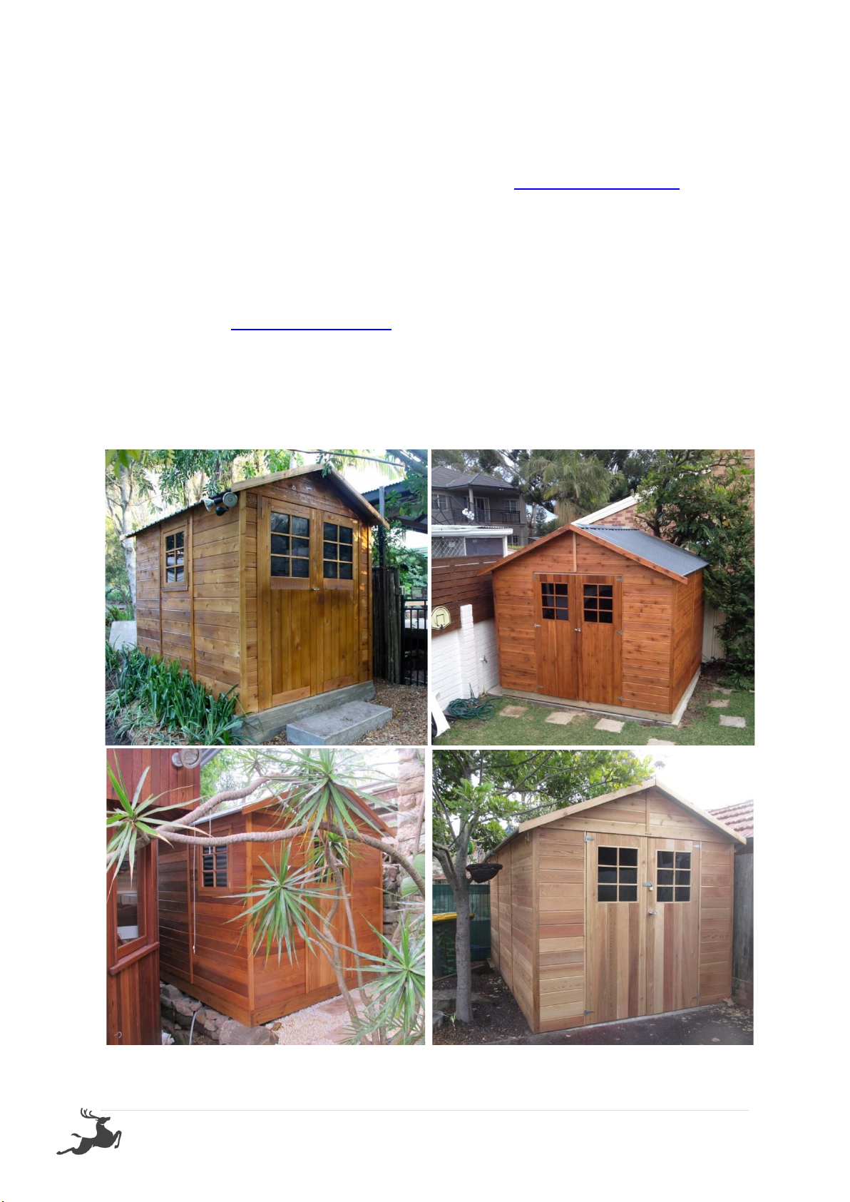
SHOW US YOUR SHED
We would love to see a photo of your STILLA product installed in your
backyard. Please upload this image when completing the warranty registration.
Alternatively, you can send the photos by email to sales@stilla.com.au.
If you require any assistance, please feel free to call or email.
Kind regards,
STILLA Customer Support
This manual suits for next models
2
Table of contents
Other STILLA Outdoor Storage manuals


Popular Outdoor Storage manuals by other brands


X-METAL
X-METAL 4065 owner's manual

Gardiun
Gardiun Glasgow KIS12992 instruction manual

ABSCO SHEDS
ABSCO SHEDS 45302WK Assembly & instruction manual

Backyard Products
Backyard Products YardLine SOMERFIELD GABLE manual

ABSCO SHEDS
ABSCO SHEDS J30232G Assembly instructions

SPACEMAKER
SPACEMAKER 90174CL Series Owner's manual & assembly guide

Mercia Garden Products
Mercia Garden Products 10DTBARK0804-V1 Assembly instructions

Fishers Woodscraft
Fishers Woodscraft Home Garden Pub Assembly instructions

garofalo
garofalo BAULE WOODY GREY 80 user manual

Lifetime
Lifetime 6418 Assembly instructions and owner's manual

Keter
Keter OAKLAND 7511 user manual

USP
USP Duramax Palladium manual