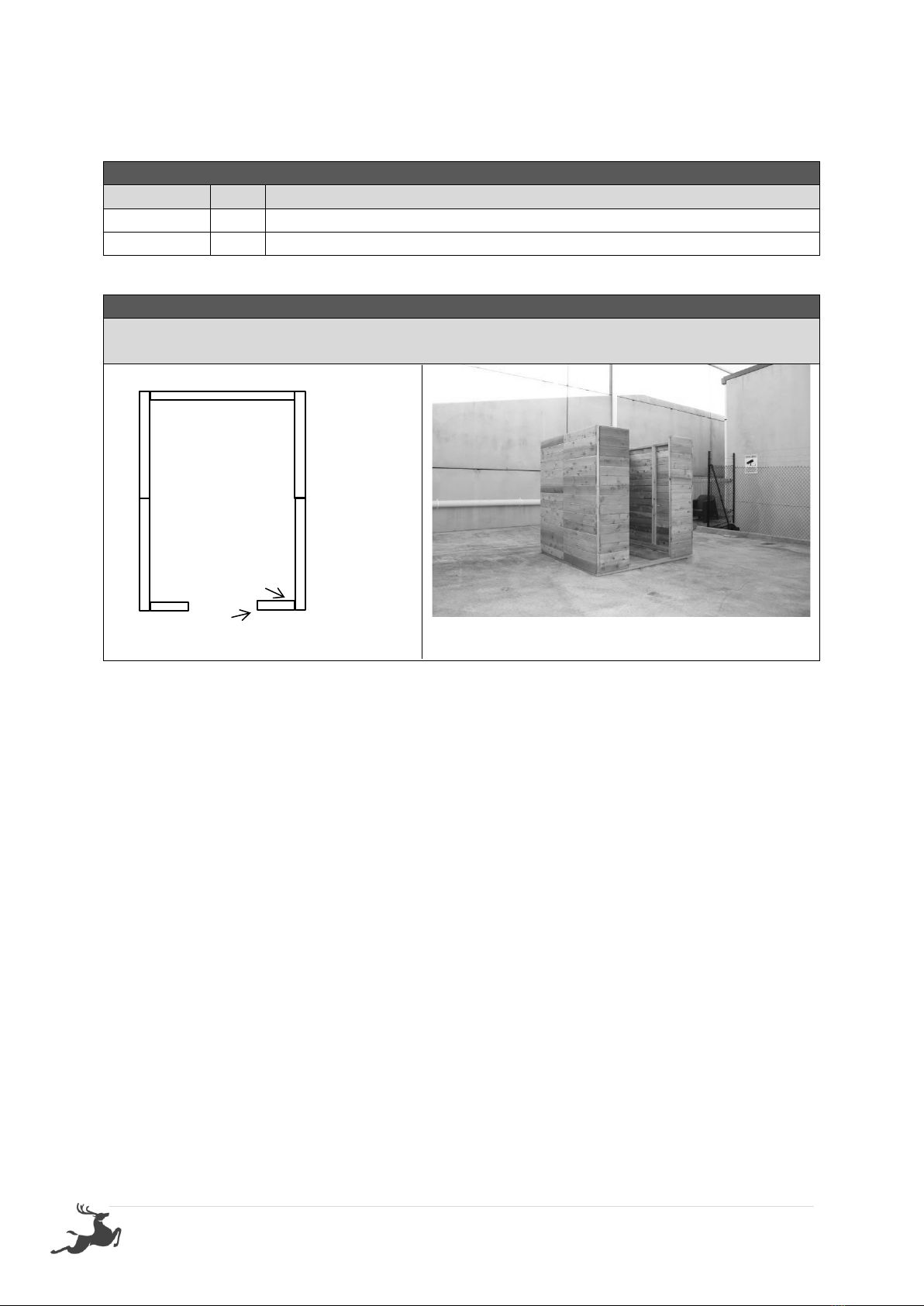
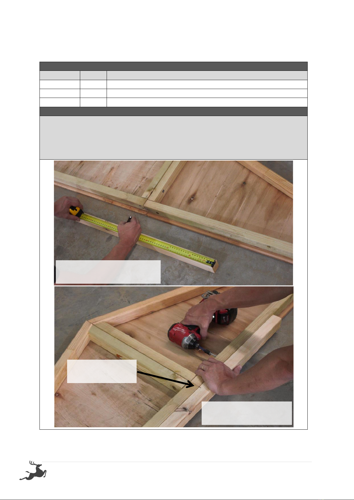
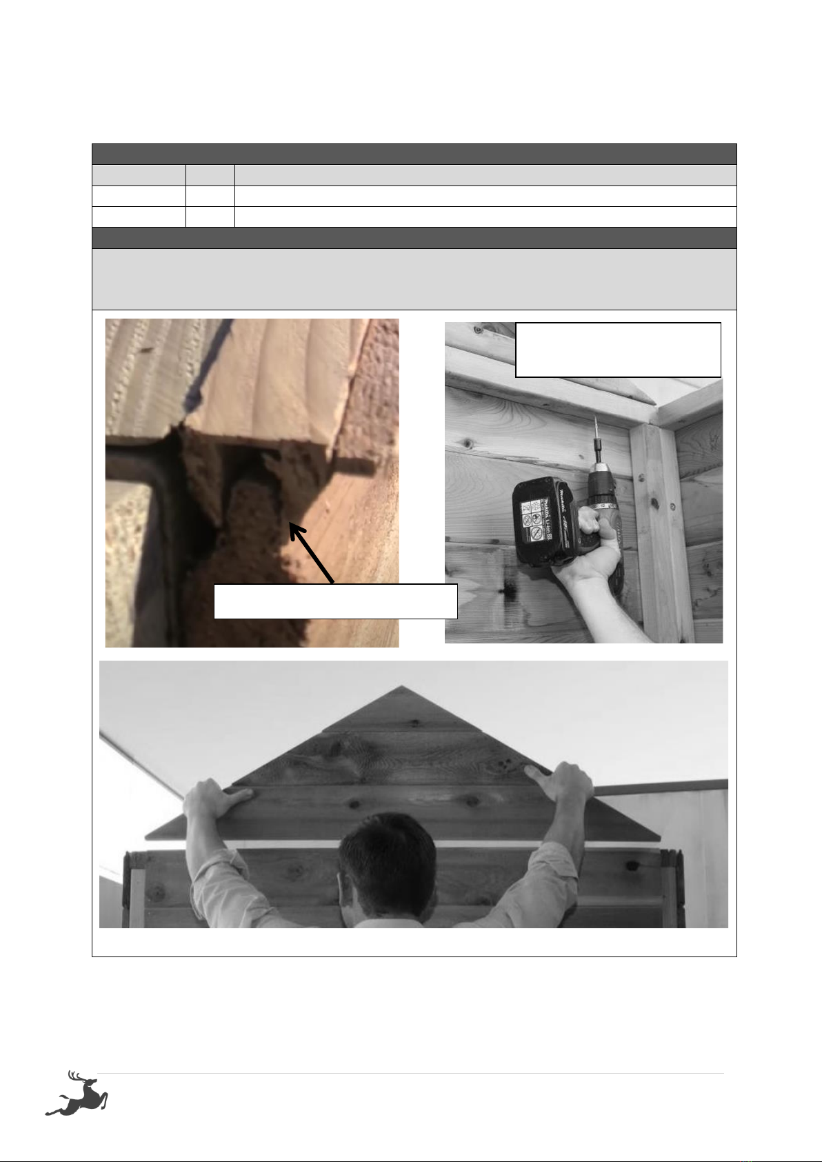
STILLA Windsor User manual

STILLA
ASSEMBLY INSTRUCTIONS
‘Windsor’4x6
S3008
Every part needed to construct your shed is included inside the pack; cedar
panels, doors, windows, hardware kits & roof sheeting. Please ensure you fully
unpack all the parts & check against the parts checklist before contacting
customer service about anything you believe may be missing. Thank-you!

1 | P a g e
Caution
Please be careful when handling all components, some parts have sharp metal edges.
Always wear work gloves, eye protection and long sleeves when assembling or maintaining
your shed.
Tools required for assembly
•Level
•Drill
•Hammer
•Ladder
•12mm Drill bit
•6mm Drill bit
•Phillips head drive
•Hex Head Drive (5/16’)
•Safety glasses
•Gloves
Before assembly
•Before proceeding with installation, we recommend viewing the Cedar Shed video at
www.stilla.com.au/installation/ or search Stilla Classic Cedar Sheds on Youtube. This doesn’t
show the installation in detail however it could give you some handy tips. Please note we
haven’t videoed the assembly of each shed however the video online is the Maple 12x6 and
will give you an overall idea on how the installation process is completed.
•Remove all parts from packages and place in a safe place close to assembly area.
•Review all instructions; continue to refer to instructions throughout assembly –step
by step.
Preparing your site
•If you are installing your shed on the Stilla rebated floor we recommend finding a
place in your yard that is very close to level. Pavers or a solid material that will not be
affected by weather can be used to perfectly level the shed by placing under the
floor frame where required, make sure all members are supported.
•If you are installing your shed on the Stilla heavy duty floor, this can be placed on
unlevelled surfaces and levelled up by using the 100x100 stumps provided.

2 | P a g e
WINDSOR 4x6 PARTS CHECKLIST
Part Code
Checked
Part Description
Qty
9P
Cedar Clad Panel 900x1895mm
4
12P
Cedar Clad Panel 1200x1895mm
1
FP
Cedar Clad Panel 180x1895mm
2
D
4x6 Standard Door 830x1875 –Full Cedar
1
FG
4ft Front Gable
1
BG
4ft Back Gable
1
CP
Corner Post 1890x60x18mm
4
CS
Cover Strip 1890x40x7mm
2
F
4ft Fascia Pack (4)
1
R
Roof Rafters 580x70x45mm
6
DH
Door Head 840x35x42mm
1
DS
Door Step 840x42x19mm
1
E
Roof End Piece 203x70x30mm
12
RS
880mm Sheeting
6
RC
1200mm Ridge Cap
2
C
1060mm Channel
4
HK
4x6 Hardware Kit
1
IM
4x6 Instruction Manual
1
REP
Roof End Plate 1714x70x45mm
4
Floor Kit –Option
Floor Frame - 140x38mm
Part Code
Checked
Part Description
Qty
EP
End Plate 1800x140x38mm
2
DJ
Double Joist 1208x140x38mm
2
SJ
Single Joist 1208x140x38mm
3
L
Logs 750mm
4
FB
1713mm x 800mm
1
FB
1713mm x 395mm
1
Elevation Kit –Option
Must Include a Heavy Duty Floor
Part Code
Checked
Part Description
Qty
SR
Stair Risers (Pair) 1200mm
2
ST
Stair Treads 240x45x900mm
5
EKFIX
Fixings - Bolt (With Nut) M12 x 60 Galvanised
24
P
Post 100x100 @ 1500mm
4

3 | P a g e
If no floor option was purchased, go to step 2.0 (Wall Assembly)
SKIP TO BACK FOR IMAGES TO HELP WITH FLOOR INSTALL
STEP 1.0
FLOOR KIT
1.0 –FLOOR KIT
PART CODE
QTY
DESCRIPTION
EP
2
End Plate 1800mm
SJ
3
Single Joist 1208mm
DJ
2
Double Joist 1208mm
100BS
24
100mm Batten Screw
1.0 –FLOOR FRAME
Fasten floor frame together as indicated in diagram below, using lines and predrilled holes.
Screw through EP into DJ using 3x 100BS.
Screw through EP into SJ using 2 x 100BS per join.
Ensure frame is square by measuring from corner to corner diagonally, frame will be square
when both diagonal measurements equal the same.
ENSURE 42x35 side of the DJ sits at top.

4 | P a g e
STEP 1.1
FLOOR FRAME INSTALLATION
The 6x6 floor frame comes in one part. Install floor frame in desired position at desired
height and fasten to logs once level and square.
1.1 –FLOOR FRAME INSTALLATION
PART CODE
QTY
DESCRIPTION
L
4
Logs 750x100x100mm
100BS
16
100mm batten screws
200PB
4
200mm M12 Post Bolt
W
8
M12 Washers
1.1 –FLOOR FRAME INSTALLATION
1. Lay out frame in desired position and mark holes to dig, as indicated on diagram
below (use shovel or marking paint).
2. Dig and place logs in holes (using concrete if you wish).
3. Fasten floor frame to logs at desired height, using 4x 100BS per log, ensuring frame is
level*.
* Fasten frame to logs when roughly level and then critique by hammering in or adding dirt
(or concrete) to corners until perfectly level at every post.
Once frame is installed, predrill holes (using a 13mm drill bit) and bolt each log to the floor
frame in spots indicated with 200PB, using washers on both sides.

5 | P a g e
STEP 1.2
FLOOR INSTALLATION
1.2 –FLOORING INSTALLATION
PART CODE
QTY
DESCRIPTION
FB
2
Floor Board 1713x800mm
FB
1
Floor Board 1713x395mm
50PS
25
50mm Philips Screw
1.2–FLOORING INSTALLATION
Fasten floor sheets to floor frame as shown in diagram below using 50PS.
Bring Floor sheets in 43mm on all 4 sides from the outside of the floor frame.
Note- The x marked on the floor sheets do not line up with out joists.

6 | P a g e
STEP 2.0
WALL ASSEMBLY
2.0 - ASSEMBLY PARTS –WALL ASSEMBLY
PART CODE
QTY
DESCRIPTION
FP
1
Front Wall panel
9P
1
900mm Wall panel
65HHS
3
65mm Hex head screw
–If optional window was purchased, it can take the place of any 900mm (9P) panel.
2.0 - ASSEMBLY –WALL ASSEMBLY
Screw through FP into 9P (top, centre & bottom) using 3 x 65HHS. (Holding studs flush on
the outside)
Note: Ensure tongue on VJ cladding is facing upwards.
9P
Screw 3 x
65HHS (Top,
centre &
bottom)
FP
Cedar Strip
When screwing the four corners together please make sure the studs are flush on the
outside (not the inside) as per image below.

7 | P a g e
STEP 2.1
WALL ASSEMBLY
2.1 - ASSEMBLY PARTS –WALL ASSEMBLY
PART CODE
QTY
DESCRIPTION
9P
1
900mm Wall panel
65HHS
3
65mm Hex head screw
2.1 - ASSEMBLY –WALL ASSEMBLY
Screw through 9P into 9P (Top, centre & bottom) using 3 x 65HHS, holding studs flush on the
inside.
9P
Screw 3 x 65HHS
(Top, centre &
bottom)
FRONT OF SHED
9P

8 | P a g e
STEP 2.2
WALL ASSEMBLY
2.2 - ASSEMBLY PARTS –WALL ASSEMBLY
PART CODE
QTY
DESCRIPTION
12P
1
1200mm Wall panel
65HHS
3
65mm Hex head screw
2.2 - ASSEMBLY –WALL ASSEMBLY
Screw through 12P into 9P (Top, centre & bottom) using 3 x 65HHS, holding studs flush on
the outside.
12P
Screw 3 x
65HHS (Top,
centre &
bottom)
FRONT OF SHED
9P

9 | P a g e
STEP 2.3
WALL ASSEMBLY
2.3 - ASSEMBLY PARTS –WALL ASSEMBLY
PART CODE
QTY
DESCRIPTION
9P
1
900mm Wall panel
65HHS
3
65mm Hex head screw
2.3 - ASSEMBLY –WALL ASSEMBLY
Screw through 12P into 9P (top, centre & bottom) using 3 x 65HHS holding studs flush on
the outside.
Screw 3 x 65HHS
(Top, centre &
bottom)
12P
9P

10 | P a g e
STEP 2.4
WALL ASSEMBLY
2.4 - ASSEMBLY PARTS –WALL ASSEMBLY
PART CODE
QTY
DESCRIPTION
9P
1
900mm Wall panel
65HHS
3
65mm Hex head screw
2.4 - ASSEMBLY –WALL ASSEMBLY
Screw through 9P into 9P (top, centre & bottom) using 3 x 65HHS holding studs flush on the
inside.
Screw 3 x
65HHS (Top,
centre &
bottom)
FRONT OF SHED
9P
9P

11 | P a g e
STEP 2.5
WALL ASSEMBLY
2.5 - ASSEMBLY PARTS –WALL ASSEMBLY
PART CODE
QTY
DESCRIPTION
FP
1
Front Wall panel
65HHS
3
65mm Hex head screw
2.5 - ASSEMBLY –WALL ASSEMBLY
Screw through FP into 9P (top, centre & bottom) using 3 x 65HHS holding studs flush on the
outside.
Screw 3 x 65HHS
(Top, centre &
bottom)
FRONT OF SHED
FP
9P
Cedar Strip

12 | P a g e
STEP 2.6
DOOR STEP INSTALL
2.6 - ASSEMBLY PARTS –DOOR STEP INSTALL
PART CODE
QTY
DESCRIPTION
DS
1
840x42x19mm Door Step (Replace with 1440 DS if DD)
40N
4
40mm Nail
2.6- ASSEMBLY –DOOR STEP INSTALL
Nail Door Step in position using 4x 40N* as seen below. Ensure wall panels are tight against DS.
* This is if floor option was chosen. If you are installing on concrete slab, use small dyno bolts to
fasten (not provided).

13 | P a g e
STEP 2.7
DOOR HEAD ASSEMBLY
2.7 - ASSEMBLY PARTS –DOOR HEAD ASSEMBLY
PART CODE
QTY
DESCRIPTION
FG
1
Front End 4ft Gable
DH
1
840x42x35mm Door Head (replace with 1440mm DH if DD)
65HHS
4
65mm Hex head screw
2.7 - ASSEMBLY –DOOR HEAD ASSEMBLY
Measure and mark middle of Door Head (DH)*. Lay Assembled front end Gable on a flat
surface with the frame facing upwards, as seen below. Line up middle mark on DH with
gable join centre, hold and screw down through gable into DH using 4x 65HHS- 2 either
side of gable join (as seen below).
* 420mm mark for SD / 720mm mark for DD.
Measure and mark middle of
Door Head
Screw through gable frame
into Door Head
Centre Door Head in
middle of Gable

14 | P a g e
STEP 2.8
FRONT END GABLE INSTALL
2.8 - ASSEMBLY PARTS –FRONT END GABLE INSTALL
PART CODE
QTY
DESCRIPTION
FG
1
Front End 4ft Gable
65HHS
4
65mm Hex head screw
2.8 - ASSEMBLY –FRONT END GABLE INSTALL
Carefully place assembled gable on front wall, ensuring groove on gable slots into the tongue
on the wall, as seen below. Ensure end of gable sits flush with side of back wall panel and
fasten by screwing 4x 65HHS through panels into gable- 2 screws either side of join.
Ensure groove slots into tongue
Screw upwards through
wall panel into gable

15 | P a g e
STEP 2.9
BACK END GABLE INSTALL
2.9 - ASSEMBLY PARTS –BACK END GABLE INSTALL
PART CODE
QTY
DESCRIPTION
BG
1
Back End 4ft Gable
65HHS
4
65mm Hex head screw
2.9 - ASSEMBLY –BACK END GABLE INSTALL
Carefully place assembled gable on back wall, ensuring groove on gable slots into the tongue
on the wall, as seen below. Ensure end of gable sits flush with side of back wall panel and
fasten by screwing 4x 65HHS through panels into gable- 2 screws either side of join.
Ensure groove slots into tongue
Screw upwards through
wall panel into gable

16 | P a g e
STEP 3.0
ROOF FRAME ASSEMBLY
3.0 - ASSEMBLY PARTS –ROOF ASSEMBLY (REPEAT TWICE)
PART CODE
QTY
DESCRIPTION
REP
2
Roof End Plate 1714x70x45mm
R
3
Roof Rafter 580x70x45mm
75BS
12
75mm Batten Screw
3.0- ASSEMBLY –ROOF ASSEMBLY (1 of 2 frames)
It helps to find a flat, level surface to complete this process on.
1. Place 3x Roof Rafters (R) in between REPs as seen in diagram above and screw 75BS into
predrilled holes to assemble roof frame.
Repeat this twice.
REPEAT THIS ASSEMBLY PROCESS TWICE TO COMPLETE BOTH ROOF
FRAMES READY FOR ROOF SHEETING

17 | P a g e
STEP 3.1
ROOF ASSEMBLY
3.1 - ASSEMBLY PARTS –ROOF ASSEMBLY (ROOF SHEETS)
PART CODE
QTY
DESCRIPTION
RS
2
880mm roof sheet
40RS
2
40mm Roof screw
25RS
2
25mm Roof screw
3.1 - ASSEMBLY –ROOF ASSEMBLY (ROOF SHEETS)
It helps to find a flat, level surface to complete this process on.
Position roof sheets (RS) at either end of roof frame and fasten in place as indicated in
diagrams. Lay roof sheet (bent edge) flush with top of roof frame while hanging side of roof
sheet 203mm* over end of roof frame. Once in position, screw 25RS through pan at top**
FIRST and then (checking bottom is still overhanging 203mm from side) screw a 40RS
through rib at the bottom** to fasten roof sheet in place.
* Use 203mm “E” or tape measure when placing overhanging side of roof sheet (ENSURE
ROOF SHEET RUNS PARRELEL TO ROOF FRAME END).
** Only screw 25RS in pan at the top and 40RS in the bottom of roof sheet.
REPEAT THIS STEP FOR SECOND ROOF FRAME

18 | P a g e
STEP 3.2
ROOF ASSEMBLY
3.2 - ASSEMBLY PARTS –ROOF ASSEMBLY (ROOF SHEETS)
PART CODE
QTY
DESCRIPTION
RS
1
880mm roof sheet
40RS
2
40mm Roof screw
25RS
4
25mm Roof screw
3.2 - ASSEMBLY –ROOF ASSEMBLY (ROOF SHEETS)
Complete laying roof sheeting out on frame. Fasten roof sheets to battens in sequence
shown. 1 x 25RS either side of join at top and 1 x 40RS through rib join at bottom.
Note: Use straight edge to keep all screws in line and centre of batten.
REPEAT THIS STEP FOR SECOND ROOF FRAME

19 | P a g e
STEP 3.3
ROOF ASSEMBLY
3.3 - ASSEMBLY PARTS –ROOF ASSEMBLY
PART CODE
QTY
DESCRIPTION
40RS
7
40mm Roof screw
25RS
10
25mm Roof screw
3.3 - ASSEMBLY –ROOF ASSEMBLY
Complete screwing roof off at top. 1 x 25RS in pan beside every rib. Once top is complete
screw bottom off using 1 x 40RS through every rib.
Note: Use straight edge to keep all screws in line and centre of batten.
REPEAT THIS STEP FOR SECOND ROOF FRAME
This manual suits for next models
1
Table of contents
Other STILLA Outdoor Storage manuals
Popular Outdoor Storage manuals by other brands

Keter
Keter DARWIN 4x4 user manual

Lifetime
Lifetime 6405 Assembly instructions

Palram
Palram CANOPIA RUBICON 6x8 manual

Schaffner
Schaffner HOLZLAGER-BANK 7023 Assembly instructions

Lifetime
Lifetime 6422 Owner's manual outdoor storage keep this identi?cation number in case you need to contact our custom

Palram
Palram RUBICON manual

Mercia Garden Products
Mercia Garden Products 0628LOG233-V4 General instructions

garofalo
garofalo BOX FLAT 100 user manual

GRE
GRE DECK1 Assembly instructions

Lifetime
Lifetime 60212 Assembly instructions

Mercia Garden Products
Mercia Garden Products 07PORHEL1008-V1 General instructions

ABSCO SHEDS
ABSCO SHEDS PPCK Assembly & instruction manual