STILLA Peppertree 9x6 User manual

STILLA
ASSEMBLY INSTRUCTIONS
‘Peppertree’9x6
S3081
Every part needed to construct your shed is included inside the pack; cedar
panels, doors, windows, hardware kits & roof sheeting. Please ensure you fully
unpack all the parts & check against the parts checklist before contacting
customer service about anything you believe may be missing. Thank-you!

24/10/2023
1 | P a g e
Caution
Please be careful when handling all components, some parts have sharp metal edges.
Always wear work gloves, eye protection and long sleeves when assembling or maintaining
your shed.
Tools required for assembly
•Level
•Drill (capable of driving 100mm
Batten Screw)
•Hammer
•Ladder
•10mm Drill bit
•6mm Drill bit
•Tape measure
•Phillips head drive
•Hex Head Drive (5/16’)
•Safety glasses
•Gloves
•Circular/power saw (if heavy duty
floor was chosen)
•4mm Alan key
•Batten screw drive
Before assembly
•Before proceeding with installation, we recommend viewing the Cedar Studio video
at www.stilla.com.au/installation/ or search Stilla Cedar Studios on Youtube. This
doesn’t show the installation in detail however it could give you some handy tips.
Please note we haven’t videoed the assembly of each shed however the video online
is the Pioneer 20x10 and will give you an overall idea on how the installation process
is completed.
•Remove all parts from packages and place in a safe place close to assembly area.
•Review all instructions; continue to refer to instructions throughout assembly –step
by step.
Preparing your site
•If you are installing your shed on the Stilla heavy duty floor, this can be placed on
unlevelled surfaces and levelled up by using the 100x100 stumps provided.

24/10/2023
2 | P a g e
PEPPERTREE 9X6 PARTS CHECKLIST
Part Code
Checked
Part Description
Qty
P
Cedar Clad Ply Panel 900x2020mm (remove 2 if DD)
7
WP
Cedar Clad Ply Window Panel 930x2020mm
2
SWA
Cedar Studio Window Assembly (add per additional WP)
2
SCD
Single Colonial Door 825x1885mm
1
G
6ft Gable
2
FP
Cedar Clad Ply Front Panel 180x2020mm (add if DD option)
2
DCD
Double Colonial Door 710x1885mm (add if DD option)
2
CP
Corner Post 2015x65x20mm
4
CS
Cover Strip 2015x40x7mm
6
CS
Fixed Cover Strip 2015x40x7mm (4x per added fixed window)
SF
6ft Studio Fascia Pack (4pcs) –140x20mm
1
R
Roof Rafter 870x70x45mm
8
CT
Collar Tie
2
SDH
Single Door Head 840x123x45mm
1
SDSS
Single Door Surround Set –2@ 840mm, 2@ 1870mm (17x17)
1
DDH
Studio Double Door Head 1440x123x45mm (add if DD option)
1
DDSS
Double Door Surround Set –2@ 1440mm, 2@ 1870mm (17x17)
(add if DD option)
1
DDS
Double Door Vertical Seal –1855x55x20mm (add if DD option)
1
SIWS
Studio Internal Window Strip Set –2@ 770mm, 2@ 1240mm
(add per additional WP)
2
E
Roof End Piece 203x70x30mm
12
RS
1120mm Roof Sheeting
8
Sky
1120mm Skylight (option- swap with 1120 RS)
RC
1800mm Ridge Cap
2
C
1520mm Channel
4
HK
9x6 Hardware Kit
1
IM
9x6 Instruction Manual
1
REP
Roof End Plate 1304x70x45mm
8
JP
Joining Plate 812x70x45mm
4
RI (option)
Roof Insulation 2700x1300mm
2

24/10/2023
3 | P a g e
Floor Kit –Option (add screws)
Floor Frame –140x35
Part Code
Checked
Part Description
Qty
EP
End Plate 1884x140x38mm
4
DJ
Double Joist 1280x140x38mm
4
SJ
Single Joist 1280x140x38mm
6
L
Logs 750mm
6
FB
1798x800mm
3
FB
1798x206mm
1
Annex Kit –Option (add screws)
3020mm x 1450mm
Part Code
Checked
Part Description
Qty
VBJ
Veranda Beam Joiner 700x70x45mm
1
VOBJ
Veranda Outer Beam Joiner 700x140x35mm
1
VB
Veranda Beam 1510x70x45mm
2
VOB
Veranda Outer Beam 1510x140x35mm
2
VR
Veranda Rafter 1320x70x45mm
4
VF
Veranda fascia 1350x140x20 block cedar
2
VRS
1450mm Veranda Roof Sheet
4
VP
Veranda Posts 2400x90x90mm
2
Annex Deck Kit –Option (add screws)
3600mm x 1420mm
Part Code
Checked
Part Description
Qty
VEP
Veranda End Plate 2700x140x35mm
2
VJ
Veranda Joists 1350x140x35
7
VFB
Veranda Floorboards 2750x140x20mm
11
VL
Veranda Logs 750x100x100mm
3
24/10/2023
4 | P a g e
If no floor option was purchased, go to step 2.0 (Wall Assembly)
SKIP TO BACK FOR IMAGES TO HELP WITH FLOOR INSTALL
STEP 1.0
FLOOR KIT
1.0 –FLOOR KIT (1 of 2 floor frames)
PART CODE
QTY
DESCRIPTION
EP
2
End Plate 1884mm
SJ
3
Single Joist 1280mm
DJ
2
Double Joist 1280mm
100BS
24
100mm Batten Screw
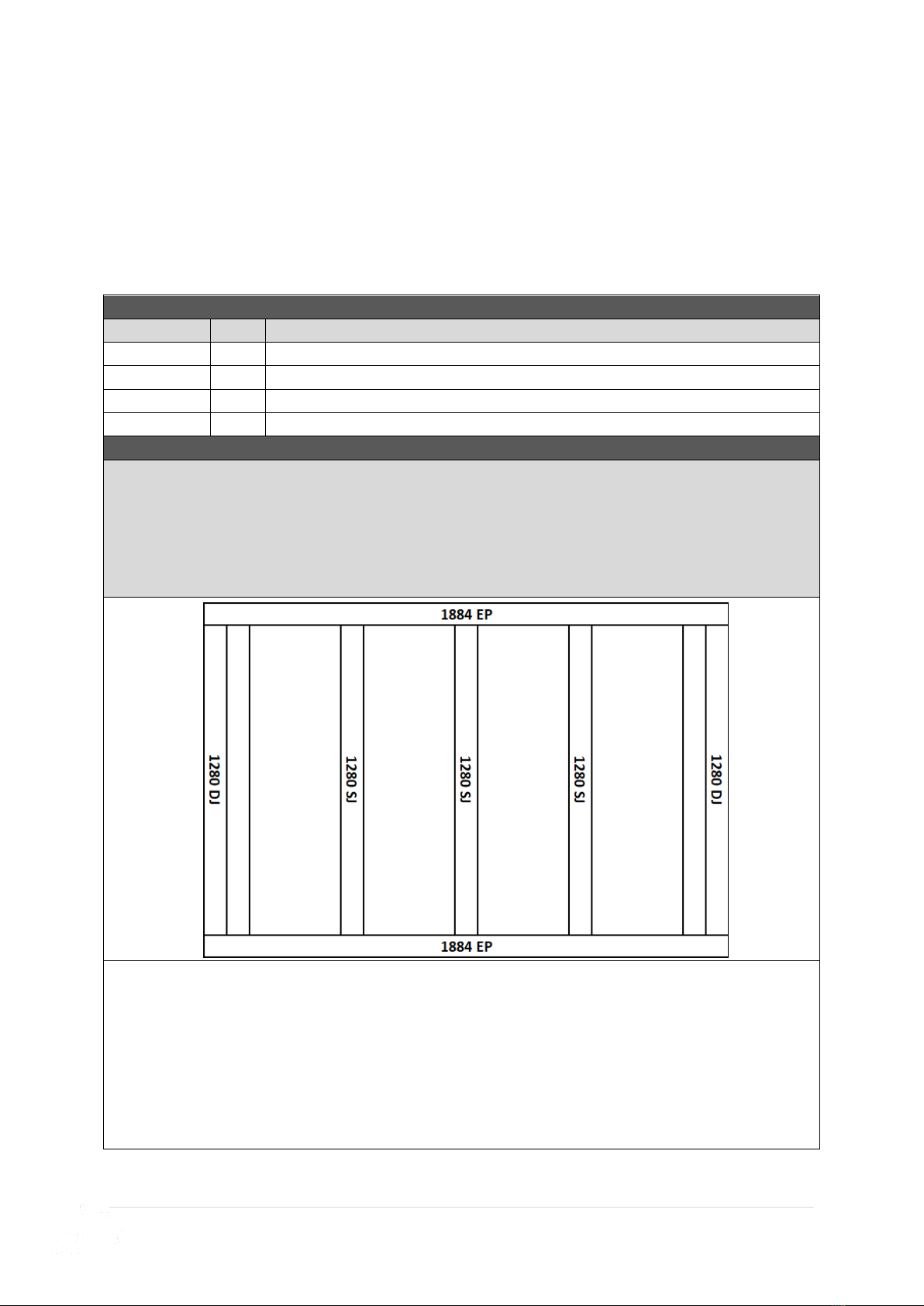
1.0 –FLOOR FRAME (1 of 2 floor frames)
Fasten floor frame together as indicated in diagram below, using lines and predrilled holes.
Screw through EP into DJ using 3x 100BS.
Screw through EP into SJ using 2 x 100BS per join.
Ensure frame is square by measuring from corner to corner diagonally, frame will be square
when both diagonal measurements equal the same.
REPEAT THIS PROCESS FOR FASTENING 1 MORE FLOOR FRAME.
ENSURE 42x35 side of the DJ sits at top.
FRONT

24/10/2023
5 | P a g e
STEP 1.1
FLOOR FRAME INSTALLATION
The 9x6 floor frame comes in two parts. Install first floor frame in desired position at
desired height and fasten to logs once level and square, then join and fasten next frame
and repeat.
1.1 –FLOOR FRAME INSTALLATION
PART CODE
QTY
DESCRIPTION
L
6
Logs 750x100x100mm
100BS
24
100mm batten screws
65BS
8
65mm Batten Screws
200PB
6
200mm M12 Post Bolt
W
12
M12 Washers
1.1 –FLOOR FRAME INSTALLATION
Repeat the steps below for each floor frame, joining the floor frames together as you go in
order displayed in diagram below.
1. Lay out frame in desired position and mark holes to dig, as indicated on diagram
below (use shovel or marking paint).
2. Dig and place logs in holes (using concrete if you wish).
3. Fasten floor frame to logs at desired height, using 4x 100BS per log, ensuring frame is
level*.
4. Butt next floor frame into installed frame and join using 8x 65BS evenly spaced along
the EP.
5. Repeat process until all frames are joined.
* Fasten frame to logs when roughly level and then critique by hammering in or adding dirt
(or concrete) to corners until perfectly level at every post.
Once all frames are joined, predrill holes (using a 13mm drill bit) and bolt each log to the
floor frame in spots indicated with 200PB, using washers on both sides.
FRONT
FRONT
FRONT

24/10/2023
6 | P a g e
STEP 1.2
FLOOR INSTALLATION
1.2 –FLOORING INSTALLATION
PART CODE
QTY
DESCRIPTION
FB
3
Floor Board 1798x800mm
FB
1
Floor Board 1798x206mm
50PS
75
50mm Philips Screw
1.2–FLOORING INSTALLATION
Fasten floor sheets to floor frame as shown in diagram below using 50PS.
Bring Floor sheets in 47mm on two EP sides from the outside of the floor frame and 44mm
from the two DJ sides as seen below.
Note- The x marked on the floor sheets do not line up with our joists.

24/10/2023
7 | P a g e
STEP 2.0
SINGLE DOOR WALL PANEL LAYOUT
The 9x6 Peppertree comes standard with a single door in the non-gable end of the shed
with two window panels either side, as seen in the plan below. Follow the steps outlined
in the following pages to assemble this plan in the correct order.
Note: Any additional window panels purchased can be positioned and replace any of the
900 panels (9P) seen on this plan.
24/10/2023
8 | P a g e
STEP 2.1
WALL ASSEMBLY
2.1 - ASSEMBLY PARTS –WALL ASSEMBLY
PART CODE
QTY
DESCRIPTION
WP
1
930mm Window Panel
P
1
900mm Panel
65HHS
3
65mm Hex head screw
2.1 - ASSEMBLY –WALL ASSEMBLY
Screw through WP into P (top, centre & bottom) using 3 x 65HHS*. Cedar strip on FWP or FP
should be on the door side.
* It helps to have one person adjusting from the outside and one person screwing on the inside.
Note: Ensure tongue on cedar cladding is at top.
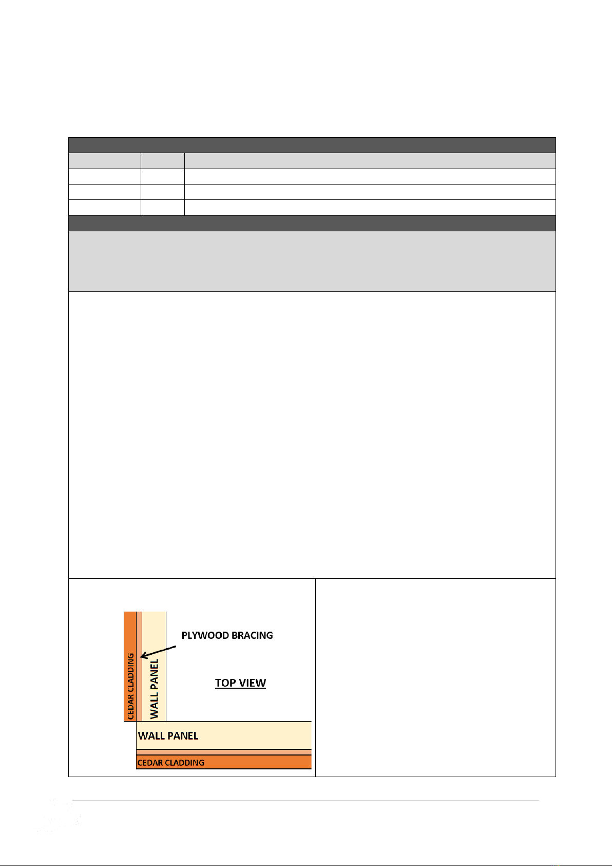
IMPORTANT CORNER DETAIL:
Install frame flush on the outside of plywood
bracing.

24/10/2023
9 | P a g e
STEP 2.2
WALL ASSEMBLY
2.2 - ASSEMBLY PARTS –WALL ASSEMBLY
PART CODE
QTY
DESCRIPTION
P
1
900mm Panel
65HHS
3
65mm Hex head screw
2.2- ASSEMBLY –WALL ASSEMBLY
Screw through P into P (top, centre & bottom) using 3 x 65HHS*.
* It helps to have one person adjusting from the outside and one person screwing on the inside.
Note: Ensure tongue on cedar cladding is at top.

24/10/2023
10 | P a g e
STEP 2.3
WALL ASSEMBLY
2.3 - ASSEMBLY PARTS –WALL ASSEMBLY
PART CODE
QTY
DESCRIPTION
P
1
900mm Panel
65HHS
3
65mm Hex head screw
2.3- ASSEMBLY –WALL ASSEMBLY
Screw through P into P (top, centre & bottom) using 3 x 65HHS*.
* It helps to have one person adjusting from the outside and one person screwing on the inside.
Note: Ensure tongue on cedar cladding is at top.
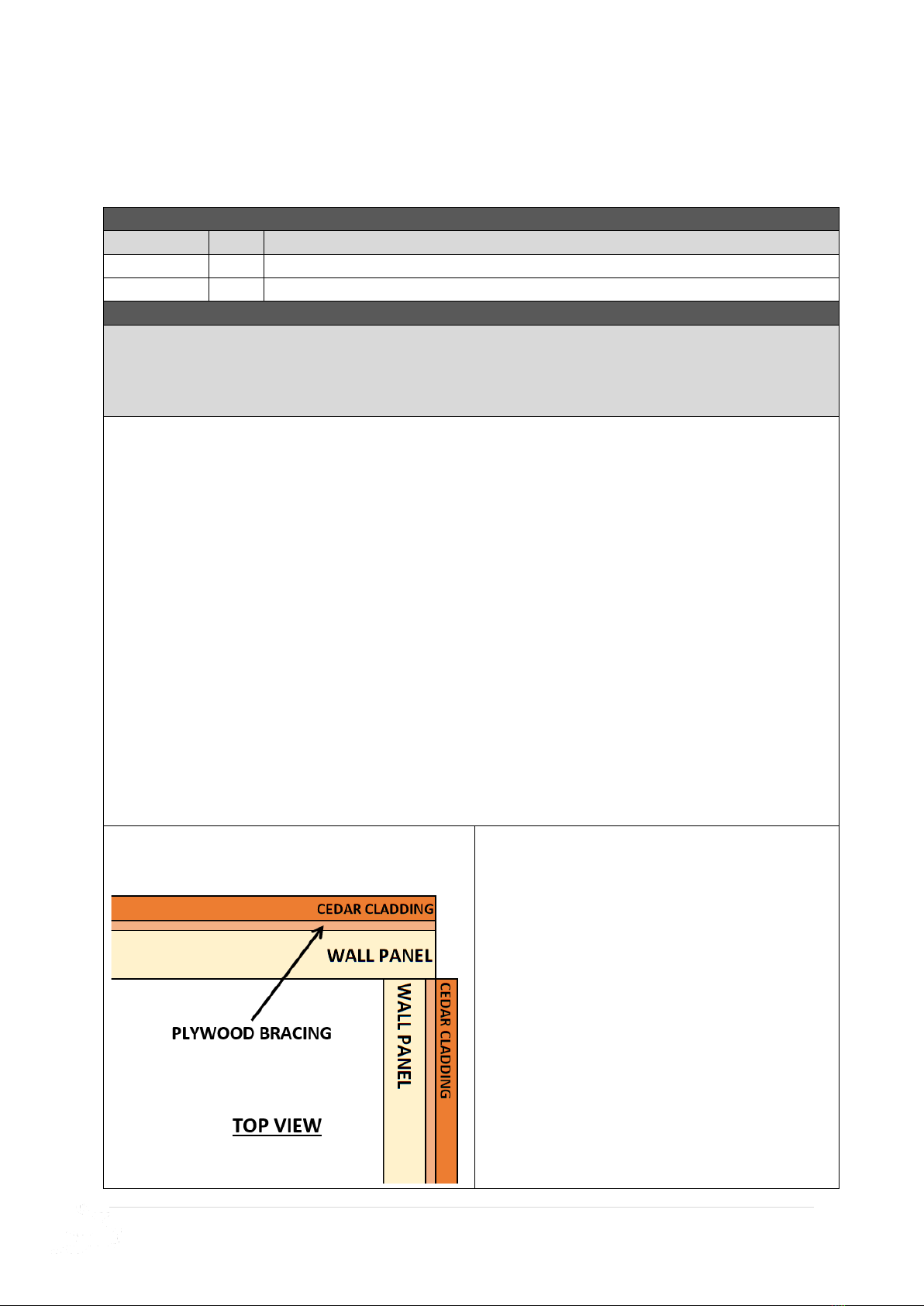
IMPORTANT CORNER DETAIL:
Install frame flush on the outside of plywood
bracing.

24/10/2023
11 | P a g e
STEP 2.4
WALL ASSEMBLY
2.4 - ASSEMBLY PARTS –WALL ASSEMBLY
PART CODE
QTY
DESCRIPTION
P
1
900mm Panel
65HHS
3
65mm Hex head screw
2.4- ASSEMBLY –WALL ASSEMBLY
Screw through P into P (top, centre & bottom) using 3 x 65HHS*.
* It helps to have one person adjusting from the outside and one person screwing on the inside.
Note: Ensure tongue on cedar cladding is at top.
24/10/2023
12 | P a g e
STEP 2.5
WALL ASSEMBLY
2.5 - ASSEMBLY PARTS –WALL ASSEMBLY
PART CODE
QTY
DESCRIPTION
P
1
900mm Panel
65HHS
3
65mm Hex head screw
2.5- ASSEMBLY –WALL ASSEMBLY
Screw through P into P (top, centre & bottom) using 3 x 65HHS*.
* It helps to have one person adjusting from the outside and one person screwing on the inside.
Note: Ensure tongue on cedar cladding is at top.
24/10/2023
13 | P a g e
STEP 2.6
WALL ASSEMBLY
2.6 - ASSEMBLY PARTS –WALL ASSEMBLY
PART CODE
QTY
DESCRIPTION
P
1
900mm Panel
65HHS
3
65mm Hex head screw
2.6- ASSEMBLY –WALL ASSEMBLY
Screw through P into P (top, centre & bottom) using 3 x 65HHS*.
* It helps to have one person adjusting from the outside and one person screwing on the inside.
Note: Ensure tongue on cedar cladding is at top.
IMPORTANT CORNER DETAIL:
Install frame flush on the outside of plywood
bracing.

24/10/2023
14 | P a g e
STEP 2.7
WALL ASSEMBLY
2.7 - ASSEMBLY PARTS –WALL ASSEMBLY
PART CODE
QTY
DESCRIPTION
P
1
900mm Panel
65HHS
3
65mm Hex head screw
2.7 - ASSEMBLY –WALL ASSEMBLY
Screw through P into P (top, centre & bottom) using 3 x 65HHS*.
* It helps to have one person adjusting from the outside and one person screwing on the inside.
Note: Ensure tongue on cedar cladding is at top.

24/10/2023
15 | P a g e
STEP 2.8
WALL ASSEMBLY
2.8 - ASSEMBLY PARTS –WALL ASSEMBLY
PART CODE
QTY
DESCRIPTION
WP
1
930mm Front Window Panel
65HHS
3
65mm Hex head screw
2.8- ASSEMBLY –WALL ASSEMBLY
Screw through WP into P (top, centre & bottom) using 3 x 65HHS*. Cedar strip on FWP or FP
should be on the door side.
* It helps to have one person adjusting from the outside and one person screwing on the inside.
Note: Ensure tongue on cedar cladding is at top.
IMPORTANT CORNER DETAIL:
Install frame flush on the outside of plywood
bracing.

24/10/2023
16 | P a g e
STEP 2.9
DOOR HEAD INSTALL (Non-Gable end)
2.9 - ASSEMBLY PARTS –DOOR HEAD INSTALL
PART CODE
QTY
DESCRIPTION
SDH
1
840x123x45mm Double Door Head
MP
2
Mending Plate
32PS
8
32mm Phillips Screw
2.9 - ASSEMBLY –DOOR HEAD INSTALL
1. Mark 75mm either side on top of door head (tongue is on top).
2. Screw Mending Plate to top of either side of Door Head using 2x 32PS.
3. Place Door Head in position. Ensure back of Door Head sits flush with back frame
of front panel.
4. Fasten Door Head by screwing 2x 32PS through mending plate into front panel.
Ensure Door Head sits hard against side of front panel.
1.
2.
3.
Ensure Door Head sits hard
against side of front panel
and flush with back frame.
4.

24/10/2023
17 | P a g e
STEP 3.0
DOOR HEAD INSTALL (non-Gable End)
3.0 - ASSEMBLY PARTS –DOOR HEAD INSTALL
PART CODE
QTY
DESCRIPTION
100BS
2
100mm batten screw
3.0 - ASSEMBLY –DOOR HEAD INSTALL
Secure Door Head by screwing 1x 100BS through front panel into bottom of Door Head, as
seen below*.
* Predrill a 4mm hole before screwing.
24/10/2023
18 | P a g e
STEP 3.1
DOOR SURROUND INSTALL
3.1 - ASSEMBLY PARTS –DOOR SURROUND INSTALL
PART CODE
QTY
DESCRIPTION
SDSS
1
Double Door Surround Set –2@ 840mm, 2@ 1870mm (DD option)
40N
20
40mm Nail
3.1 - ASSEMBLY –DOOR SURROUND INSTALL
1. Nail top 1440mm Door Surround to bottom of door head (flush with back) using 4x 40N.
2. Nail bottom 1440mm door surround to floor frame (hard against flooring) using 4x 40N*.
Ensure wall panels are tight against surround (there should be a 1440mm gap).
3. Measure and cut side 1870mm Door Surrounds to fit between top and bottom.
4. Nail side Door Surrounds, flush with back of wall panels, using 6x 40N per side.
* If floor frame was not purchased, secure bottom piece using silicone and concrete nails (not
supplied).
Nail surround flush
with back of frame
using 40N.

24/10/2023
19 | P a g e
STEP 3.2
GABLE INSTALL
3.2 - ASSEMBLY PARTS –GABLE INSTALL (1 of 2 Gables)
PART CODE
QTY
DESCRIPTION
G
1
6ft Gable
65HHS
4
65mm Hex head screw
3.2 - ASSEMBLY –GABLE INSTALL (1 of 2 Gables)
Carefully place gable on back wall, ensuring groove on gable slots into the tongue on the wall,
as seen below. Ensure end of gable sits flush with side of back wall panel and fasten by
screwing 4x 65HHS through panels into gable- 2 screws either side of join.
REPEAT THIS PROCESS FOR INSTALLING OTHER SIDE GABLE.
Ensure groove slots into tongue
Screw upwards through
wall panel into gable
This manual suits for next models
1
Table of contents
Other STILLA Outdoor Storage manuals


Popular Outdoor Storage manuals by other brands


Arrow Storage Products
Arrow Storage Products SpaceMaker RMA108CL owner's manual

ABSCO SHEDS
ABSCO SHEDS 23151SK-PTX manual

Backyard Products
Backyard Products HANDY HOME PRODUCTS MARCO Series Assembly manual

Duratuf
Duratuf PG66 Assembly instructions

Yardline
Yardline RIDGEPOINTE Assembly manual

USP
USP DURAMAX 6 Ft WoodSide owner's manual


