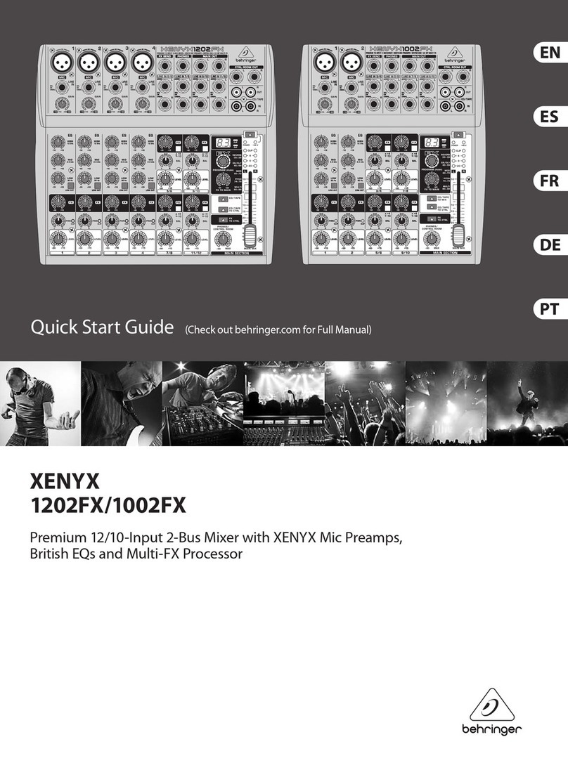
STK Professional Audio SM-16S DDR PowerPlus User manual

SM-16S DDR PowerPlus
Digital Stereo Powered Mixer
OWNER'S MANUAL ENGLISH

2
The new SM16S-DDR powered stereo mixing consoles are professional quality products
combining a full featured mixing console with stereo graphic equalizers, digital signal
processing and integrated stereo power amplification. The mixer and equalizer/amplifier
sections can be electronically separated allowing complete flexibility in a variety of
applications.
The SM16S-DDR each feature oversized heat sinks along with two speed, direct air cooling
for trouble free operation under the most adverse conditions. In addition, both models have a
bar LED display to performance conditions. While providing powerful, accurate and reliable
performance along with outstanding value, your STK new SM16S-DDR powered mixing
console has been designed for many years of dependable service.
Please take the time to read this manual before operation so that your fully understand the
features and correct use of this fine product.
SM-16S D D R
Digital Stereo Powered Mixer
Table Of Contents
1
Introduction.......................................... ........
2
2
Important Safety Instructions....................... ..........
3
3
Warranty Information..........................................
4
4
Panel Description.............................................
5-11
5
Connecting Your System........................................
12-13
6
Operating Your System.. .......................................
14-15
7
System Hookup Diagram.........................................
16-18
8
Block Diagrams................................................
19-20
9
Specifications........................................ ........
21-22
1.Introduction

3
2.Impotant Safety Instructions
1. Read Instructions- All the safety and operating instructions should be read before the
appliance is operated.
2. Retain Instructions- The safety and operating instructions should be retained for future
reference.
3. Heed Warnings- All warnings on this appliance and in the operating instructions should be
adhered to.
4. Follow Instructions- All instructions should be followed.
5. Water and Moisture- This appliance should not be used near water- for example, near a
bathtub, sink, laundry tub, in a wet basement, near a swimming pool, etc.
6. Heat- This appliance should be situated away from heat sources such as radiators, heat
registers, stoves, or other appliances (including amplifiers) that produce heat.
7. Power Sources- This appliance should be connected to a power supply only of the type
described in the operating instructions or as marked on the appliance. if you are not sure
of the type of power supply to your home, consult your appliance dealer or local power
company. For appliances intended to operate from battery power, or other sources, refer to
the operating instructions.
8. Polarization- If the appliance is equipped with a polarized alternating-current line plug
(a plug having one blade wider than the other), this plug will fit into the power outlet only
one way. This is a safety feature. if you are unable to insert the plug fully into the outlet,
try reversing the plug. if the plug should still fail to fit, contact your electrician to replace
your obsolete outlet. Do not defeat the safety purpose of the polarized plug.
9. Grounding- If the appliance is equipped with a 3-wire grounding-type plug, a plug having
a third (grounding) pin, this plug will only fit into a grounding-type power outlet.
This is safety feature. if you are unable to insert the plug into the outlet, contact your
electrician to replace your obsolete outlet. Do not defeat the safety purpose of the
grounding-type plug.
10. Power Cord Protection- Power supply cords should be routed so that they are not
likely to be walked on or pinched by items placed upon or against them, paying particular
attention to cords at plugs, convenience receptacles, and the point where they exit from
the appliance.
11. Damage Requiring Service- Unplug this appliance from the wall outlet and refer servicing
to qualified service personnel under the following conditions:
a. When the power-supply cord or plug is damaged.
b. If liquid has been spilled, or objects have fallen into the appliance.
c. If the appliance has been exposed to rain or water.
d. If the appliance does not operate normally by following the operating Instructions.
Adjust only those controls that are covered by the operating instructions as an improper
adjustment of other controls may result in damage and will often require extensive work
by a qualified technician to restore the appliance to its normal operation.
e. If the appliance has been dropped or the cabinet has been damaged.
f. When the appliance exhibits a distinct change in performance-this indicates a need for
service.
12. Servicing- Do not attempt to service this appliance yourself as opening or removing
covers may expose you to dangerous voltage or other hazards.
Refer all servicing to qualified service personnel.

4
3.Warranty Information
UNPACKING
As a part of our system of quality control,
every STK product is carefully inspected
before leaving the factory to insure flawless
appearance.
After unpacking, please inspect for any
physical damage. Save the shipping carton
and all packing materials, as they were
carefully designed to reduce the possibility
of transportation damage should the unit
again require packing and shipping.
In the event that damage has occurred,
immediately notify our dealer so that a
written claim to cover the damage can be
initiated with the carrier. The right to any
claim against a public carrier can be
forfeited if the carrier is not promptly notified
and if the shipping carton and packing
materials are not available for inspection by
the carrier. Save all packing materials until
the claim has been settled.
STK Customer Service Department
369-2 KURAERI YANGCHON-MYUN KIMPO-CITY
KYUNGGI-DO, KOREA.
TEL : +82-31-981-1788 FAX : +82-31-981-1784
E-mail : stkcom@stkpro.com
http://www.stkpro.com
STK LIMITED 1 YEAR WARRANTY
STK electronics are warranted to be free from
defects in materials and workmanship under
normal use for a period of 1 year from date
of original purchase.
During that period, STK will at its option,
repair or replace materials at no charge if
product has been delivered to STK by an
STK dealer or STK Service Center together
with the original sales receipt or other proof
of purchase. Warranty excludes fuses, exterior
finish, normal wear, failure due to abuse, or
operation outside of specified ratings. Warranty
applies to original purchaser only.
This warranty gives you specifically rights
which vary from state to state.
For more information about warranty repair,
please contact:
Customer Service Dept.,
The STK Professional Audio.
FOR YOUR RECORDS
All of us at STK thank you for your
expression of confidence in STK products.
The unit you have purchased is protected by
a limited 1 year warranty. To establish the
warranty, be sure to fill out and mail the
warranty card attached to your product.
For you own protection, fill out the information below for you own records.
Model Number
Serial Number
Dealer
Date Of Purchase
Salesman
Phone
Other Information

5
Note: The operation of the SM16S-DDR Mixer
is nearly identical.
This manual will help you understand and get the
most out of all SM console powered mixers.
FRONT PANEL
A . M o n a u r a l I n p u t C h a n n e l
1. Mic In
This input accepts a standard XLR microphone
connector and low impedance microphone.
2. Line In
This input accepts a 1/4inch two conductor plug
and is suitable for unbalanced line level sources.
2a. Channel Insert Jack.
Allows interface to external signal processing
devices, or direct channel output. 1/4" connector Tip
is Send, Ring is Return and Sleeve is Ground.
This patch point allows you to insert a compressor,
equalizer or any other signal processing device into
any of the SM16S-DDR input channel strips.
3. Low Cut Switch.
75Hz 18dB/octave low-cut filter eliminates unwanted
subsonic frequencies, while still allowing full use of
the low equalization control.(8)
4. Line Trim/Mic Gain.
Simultaneously adjusts the mic input gain to accept
signals from -10dBm to -60dBm, and trims the line
input to accept signals from +10dBm to -40dBm.
5. High Equalization.
Provides ±15dB of shelving equalization control
to boost or cut high frequency signals of 12kHz and
above.
6. Mid Equalization: Level.
Provides ±12dB of Cut/Boost to the midrange
frequency signals. The frequency range affected
depends on the setting of the mid EQ frequency
control (7). CH5-8 is ±15dB of shelving equalization
for mid high and mid low frequency control.
7. Mid Equalization: Frequency.
Adjusts the center frequency of the peak/dip midrange
control (6) from 100Hz to 8kHz
CH 5-8 is 4 band equalizer with High mid and Low mid.
8. Low Equalization.
Provides ±15dB of shelving equalization control to
boost or cut low frequency signals 80Hz and below.
9. Monitor Send.
Adjusts the amount of channel input signal sent to
the monitor output. Monitor send is post-EQ and
pre-fader.
10. Aux1 Send.
Adjusts the amount of the channel input signal
supplied to the Aux1 output. Aux1 send is post-EQ
and factory-configured for post-fader operation.
11. Aux2 Send.
Adjusts the amount of the channel input signal
supplied to the Aux2 output. Aux2 send is post-EQ
and post-fader.
12. Pan.
Sends the post fader signal to the left and right
master outputs. In the center position, the signal is
equally sent to both the left and right master outputs.
13. Peak Indicator LED.
The red LED near the pan pot is marked
Peak,
and
that stands for Overload. The channel strip overload
circuit constantly checked at a critical point in the
channel strip, just after the EQ circuit. If the channel
strip amplifiers are begin too loud into overload, the
Peak
light will flash bright red. You need to find out
which source is too high and make things right. Start
by returning down the
Gain
control until the
Peak
LED no longer light.
4. Panel Descriptions

6
14. Solo Switsh.
A s o l o s w i t c h t h e s i g n a l s e l e c t e d f o r l i s t e n i n g i n t h e h e a d p h o n e s ,
a l l o w i n g t h e c h a n n e l t o b e h e a r d a l o n e , p r e -f a d e r o r p o s t -f a d e r ,
a c c o r d i n g t o t h e p o s i t i o n o f t h e s o l o m o d e s w i t c h ( 1 4 ) .
15. Channel Fader.
Providescontinuouslyvariablecontrolofthechannelo u t p u t
l e v e l t o t h e l e f t a n d r i g h t m a s t e r o u t p u t s .
B. Stereo Input Channel
1. Left (Mono) Input.
Accepts 1/4" TRS (tip/ring/sleeve) balanced input or
TS (tip/sleeve) unbalanced sources at line level. 1/4"
connector tip is "Hot", ring is "Cold" and sleeve is
"Shield". Input is routed to the left output bus.
In the absence of a plug in the right input (2), the
left input signal is also provided to the right input, so
that the channel functions as a mono channel.
2. Right Input.
Similar to the left input (1), any inputs to this
connector are only routed to the right output bus.
3. Level Switch.
Determines the nominal input level required at the
stereo line inputs for full level. Selections are +4dBv
and -10dBV.
4. High Equalization.
Provides ±15dB of shelving equalization control
to boost or cut high frequency signals 12kHz and
above. Affects both left and right channel input
signals.
5. Mid Equalization.
Provides ±12dB of Cut/Boost to the midrange
frequency channels. This control is centered at
2.5kHz. Affects both left and right channel input
signals.
6. Low Equalization.
Provides ±15dB of shelving equalization control to
boost or cut low frequency signals of 80Hz and
below. Affects both left and right channel input
signals.
7. Monitor Send.
Adjusts the amount of mono-summed channel input
signal supplied to the monitor output. Monitor send is
post-EQ and pre-fader.
8.Aux1Send.
Adjusts the amount of mono-summed channel input
signal supplied to the Aux1 output. Aux1 send is
post-EQ and factory-configured for post-fader
operation.
For pre-fader modific ation of Aux1
Send, please see contact STK.
9. Aux2 Send/EFX.
Determines the amount of post EQ, post fader signal
sent simultaneously to the built-in multi digital effect
unit and the EFX send control in the master section.
10. Balance.
When turned to the right, gradually attenuates the
left channel input signal. When turned to the left,
gradually attenuates the right channel input signal.
11. Sol o Swit ch.
A solo switch the signal selected for listening in the
control room and headphones, allowing the stereo
channel to be heard alone, pre-fader or post-fader,
according to the position of the solo mode switch(11).
12. Channel Fader.
Provides continuously variable control of the channel
output level to the left and right master outputs.
13. Aux Return 1, 2 (Sub 1, 2)
Allows 1/4" line level stereo input directly to the left
and right master outputs, through the level control
sub1 and sub2 (Aux1, Aux2 return control) return
Panel Descriptions

7
control (13). When no plug is inserted into the right
jack, the left input is also provided to the right
master output for mono operation.
14. Aux Sends 1&2.
Provides the unbalanced, line-level Aux1 and Aux2
output mixes on 1/4" phone jacks, for connection to
external effects or monitor systems.
15. Sub Input Channel and Level Controls
(Aux Return1,2)
Stereo sub inputs and level control dual stereo
"Sub1,2"inputs with independent level controls for the
monitor, aux1 and stereo buses can be used as effect
returns or to add just about any line level signal to
the corresponding busses. Both inputs also feature
Solo switches.
C. Master Section
1. Tape Input (L/R).
Allows a stereo tape machine, CD player or similar
device to be attached via unbalanced RCA
connections, and auditioned in the headphone output.
To route the tape input to the headphone output.
2. Tape Output (L/R).
Derived directly from the left/right master output,
allows convenient connection, via unbalanced RCA
jacks, to any tape/recording device.
3. Subwoofer O utpu t Jack.
This line level subwoofer output allow you to
conveniently add supplemental bass to your system.
The signal is derived from the summed left+right
master output or the master output and is routed
through a 125Hz low pass filter.
4. Monitor Output.
Delivers the monitor output mix, through the monitor
output level control(27).
5. Main Output.
These two 1/4″connectors provide a direct feed from
the final output of the master stereo mix.
The level of these is controlled by the main left and
right level control.
6. Amp Input (Jack) & Level
These two 1/4″inputs can be used for connecting a
source device directly to the main left and right EQ
and power amplifier sections of your powered mixer.
Inserting connectors into these jacks will disconnect
the mixer section from the graphic equalizers and the
power amplifiers.
Amp Input controls are repeatable adjustment.
7. Amp Mode Selector & Level.
Two separate power amplifiers and graphic equalizers
that function in two different modes: stereo or L+R/
Monitor.
If the amp/mode switch is in the stereo position (not
pushed in), the unit is in the left+right mode.
The upper EQ/power amplifier gets its signal from
the left bus, and the lower power amplifier from the
right bus. The level to both amps is controlled by the
Master level control.
If the amp assign switch si the L+R/monitor
position(pushed in), the unit is in the main+monitor
mode. The upper EQ/power amp receivers a summed
left and right main signal and the master level control
is used to adjust the level of this signal (main
speakers.) the lower EQ/power amp receives the
monitor signal and the monitor level control is used
to adjust the level for this signal(monitors).
Panel Descriptions

8
8. DSP Foo tswi tch Jack
The Effect footswitch jack is a stand 1/4" size
accommodating a monaural ON/OFF footswitch
that enables/disable the internal digital effect.
9. Headphone Output.
Connect stereo headphones here for channel
monitoring and curing. Control of the headphone
output is supplied by the headphone output level
control (14)
10. Phantom Power Indicator LED
This LED glows green when the phantom power
circuit has been engaged.
11. Power LED
This LED glows green to indicate that the unit has
been switched on and that AC power has been
applied.
12. Protect LED
Your STK SM16S-DDR is equipped with a built-in
output protection circuit. This LED glows red when
there is a system problem and the amplifier has shut
down to protect itself and any attached equipment
from damage due to an electronic fault or improper
usage. The first thing you should do is check all of
your connections for proper wiring.
13. Effect To M oni tor Cont rol
This control lets you add reverb or other effects to
the monitor output.
14. Headphone Outp ut Level.
Sets the output level to the headphone output jack
and control.
15. Meter Assembly.
Allows visual monitoring of whichever signals are
assigned to headphone outputs. When any signal is in
AFL solo mode, that signal's level is shown on the
left and right meters. When any signal is in PFL solo
mode, the right meter shows that signal's input level.
16. Level Set Indicator.
Lights when PFL solo mode is active, indicating that
the right meter is displaying that signal's true input
level. This mode is useful for ensuring that each
input's level is correct.
17. Sol o Act ive Indica tor .
Lights to indicate that AFL or PFL solo mode is
activated on one or more input channels.
18. Phone Source Select: Monitor.
Directs the monitor outputs to the headphone output.
19. Phone Source Select: L/R Master.
Directs the left and right master outputs to the head-
phone output.
20. Phone Source Select: Mono Output.
Directs the mono output to the headphone output.
21. Sol o Mode Swi tch. (PFL/AFL)
Controls whether solo feature is
1) After-fader listen (AFL) up position
2) Pre-fader listen (PFL) down position
22. DSP On/Off Switch
This push control activates/deactivates the DSP
Effects.
23. Digital Mode Select Switch(Up/Down)
The mode control allows for the selection of 99
different types of effect sounds.
Digital Sign al Processor Function and Featur es
The STK digital reverbs gives the power to create
original sounds with a side range of effects.
99 effect patch(effect setting) can be stored in the
internal memory, calling up any patch is quick and easy.
FEATURES
* Real 99 stereo-Effect preset available divided into 26
combination and 63 single effect sound.
* An integrated E2-ROM watchdog is bypassing
the storage device.
* Easy program selection methods by 2 key which can't
preset up and down.
* The once choose preset number is automatically stored
by on board E2-PROM.
* 2-digital 7-segment numeric display interface for preset
1-99 indication.
* Automatic input audio signal "overshooting" indication
circuit on-board.
* Usage of a 1M byte SRAM for superior quality stereo
reverb and delay sound.
* Usage of the famous ASAHIKASEI 24bit DSP with built
in 20 bit AD/DA stereo converter.
* 20bit delta sigma 64 x oversampling AD converter.
* 20bit delta sigma 128 x oversampling AD converter.
* 64 x oversampling ADC digital filter.
* 128 x oversampling DAC digital filter.
* CD-quality professional sound a reality.
APPLI CATIONS
* Longtime delay and repeat for moslem church.
* Very clean and bright echo feedback and delay
for european karaoke vocal sound.
* Keyboard, guitar and combos.
24. DSP Peak indicator
The purpose of the red PEAK LED is ti indicate
when digital effect input signal is dangerously close
to clipping.
25. Graphic Equalizer(Left Master)
5bandgraphicequalizersareprovidedonthefrontpanel
and may be used for stereo Left of
SM16S-DDR.
26. Graphic Equalizer(Right Master)
5bandgraphicequalizersareprovidedonthefrontpanel
and may be used for stereo Right of
SM16S-DDR.
27. Monitor L evel Con trol
This control provides independent overall adjustment
of the signal to Monitor Output, and to the Monitor
amplified output, when in Main+Monitor mode.
28. Digital Effect to Master Control
This control lets you add reverb or other effects to
the master output.
29. Master Level Control
This is "The Important Knob." It serves as the final
volume control over the master signal (or ma ster L eft
and Right signals) to the main output connector(s)
and Master amplified output.
Panel Descriptions

9
30. Mono Master Level (Subwoofer)
Provides continuously variable control over the signal
to the mono output.
31. Sub woofer Swit ch
This push control activates/deactivates the subwoofer
output.
32. Program Display
Panel Descriptions
REVERB MODE PROGRAM
DELAY MODE PROGRAM
1.Hall
2.Room
3.Plate
4.Ambient
1. Delay
2. Cross-FB
3. 3 Tab-Pan
4. One Short
Reverb Control (Potentio Meter)
Delay Control (Potentio Meter)
1.Reverb Level
2.Reverb Time
Min 0.5 Sec to Max 10 Sec
1.Delay Level
2.Delay Time
Min 50 msec to Max 1000 msec
3.Delay Repeat
Min 0 % to Max 90 %

10
REAR PANEL
1. Power Switch
This switch controls the AC mains power to your
powered mixer. Power is on when the switch is in
the on(up) position and is confirmed when the power
LED indicator is illuminated.
2. Fuse
The fuse is located in the fuse holder. (See Section 9
Specifications for the correct values.)
3. Line Cord
For safety, all units are equipped with a three
conductor line cord.
4. Phantom Power Switch
Phantom power is provided for condenser microphones
that may require such power. In the on (in) position,
this switch provides 48VDC phantom power to all
microphone inputs
5. Right/Monitor Speaker Output Jack
These two parallel speaker output jacks accept
standard 1/4"two-conductor phone plugs, providing
750 watts of power at 4 ohms, or 430 watts at 8
ohms. Load impedances less than 4 ohms will not
draw additional power and may cause the unit to go
into protect mode.
Warning: failure to correct this can result in
damage to your unit!
The function of these jacks depends upon the position
of the Amp mode select assign switch(located on the
master section of the front control panel).
If the Amp mode select assign switch is in the stereo
position (not Pushed in), the unit is in the left &
right mode. The power amplifier driving these outputs
then gets its signal from right main bus, the output
level is controlled by the master level control, and the
lower 5-band EQ is used for final equalizing of the
right side.
If the Amp mode select assign switch is in the
L+R/monitor position(pushed in), the unit is in the
Main+Monitor mode. The power amplifier driving
these outputs then gets its signal from the monitor
circuit. The output level is controlled by the monitor
level control, and the lower 5-band EQ is used for
final equalizing of the monitors.
6. Left/Main Speaker Output Jack
These two parallel speaker output jacks accept
standard 1/4"two-conductor phone plugs, providing
750 watts of power at 4 ohms, or 430 watts at
8ohms. Load impedances less than 2 ohms will not
draw additional power and may cause the unit to go
into protect mode.
Warning: failure to correct this can result in
damage to your unit!
The function of these jacks depends upon the position
of the Amp mode select assign switch(7) is in the
stereo position (not Pushed in), the unit is in the left
& right mode. The power amplifier driving these
outputs then gets its signal from left main bus, the
output level is controlled by the master level control,
and the upper 5-band EQ is used for final equalizing
of the left side.
If the Amp mode select assign switch(7) is in the
L+R/ monitor position(pushed in), the unit is in the
Main+Monitor mode. The signal from the right and
left buses is combined and feeds the power amplifier
that drive these output jacks.
The output level is controlled by the master level
control and the upper 5-band EQ is used for final
equalizing of the main speakers.
7.SPEAKON TYPE
▪Speakon Connections
Speakon connectors are purpose-built for low
voltage,
high current applications.
Each connector incorporates two pair of conductors,
labeled 1+, 1-, by convention, single.
When attaching NL4FC mating connectors, be sure to
insert the connector to its full depth, then turn the
connector 45°clockwise to lock it in place.
▪Connection Table
Output Function Pins
Left 1+,1-
Right 1+, 1-
Panel Descriptions

11
▪Connection for Stereo(two-channel) Operation
Connect the left speaker's positive terminal to the 1+
pin of output speakon connector L.
Connect the left speaker's negative terminal to the 1-
pin of output speakon connector L.
Note that the speaker load impedance must be 4
ohms or greater.
Connect the right speaker's positive terminal to the
1+ pin of output speakon connector R.
Connect the right speaker's negative terminal to the
1- pin of output speakon connector R.
Note that the speaker load impedance must be 4
ohms or greater.
Panel Descriptions

12
A. CONNECTORS
Your powered mixer uses several types of input and
output connectors.
1. XLR Input jacks
Electronically balanced inputs accept a standard XLR
male connector. Pin1=ground, pin2=hot or positive(+)
and pin3=cold or negative (-) (see Figure 1).
These connectors should be utilized for low impedance
microphones. If you are using a high impedances
microphone, it will likely have a cord with a 1/4"
connector on it. In this case, it would be appropriate
to plug such microphones into a line input, however
performance, and gain may be lessened. for best
performance. We recommend you invest in one of the
many higher quality, low impedance mics available on
the market, or alternatively, purchase an impedance
matching transformer from your dealer.
2. 1/4″Phone Input Jacks
These tip / sleeve jacks accept an unbalanced line
level signal using a normal male phone plug.
(See Figure 1.)
3. Speaker Output Jacks
The speaker output jacks are 1/4″two conductor
jacks. Their power output and function are dependent
upon the particular unit that you are using.
4. RCA Phone Jacks
The RCA jacks accept unbalanced male pin
connectors.
Figure-1
a. Female Three Pin Connector
b. Unbalanced 1/4'' Connector
B. SYSTEM HOOKUPS
Before you begin your connections, you must decide
how you will configure your sound system, mono or
stereo. Below are system variations that can be used
with your powered mixer. Carefully consider all of
them to decide which system you will use.
NOTE :
The SM powered Mixers feature flexible
patching options which make possible more variations
of setup than are presented here. Once familiarized
with the unit's capabilities, you should be able to
achieve practically any setup you desire.
Powered Stereo (SM16S-DDR)
The basic stereo setup: One or more input devices
such as a microphone, keyboard, CD player, or tape
deck: An optional external effects processor:
One or more parallel speaker systems connected to
each of the left and right sides of the output
operating in stereo : Addition of an externally
powered monitor system.
(See Hookup diagram on page 16)
P o w e r e d M a i n ( L + R ) + M o n i t o r
Hookup diagram on page 15
Now that you have decided which mode and type of
system operation you will use, You are ready to make
our system connections and settings on your
SM-powered Mixer.
(See Hookup diagram on page 15)
1. Switch everything to OFF.
This includes your SM mixer and all devices in the
system.
2. Set the Amp Assign switch to the L+R/Monitor
(in) position.
3. Connect the input devices into the six or eight
mono input channels.
Group your microphone channels and instrument
channels to make mixing easier.
4. Connect the input devices into the two
Stereo input and sub input channels:
Using standard 1/4″shielded cables, connect the
desired devices into the stereo input channels:
Keyboards, drum machines, tape programs etc.
5. Connect the tape and/or CD player.
If you are feeding a signal from a tape or CD player
into your mixer, using a stereo RCA cable, connect
the output jacks of the tape or CD player to the tape
in jacks of your mixer.
If you wish to record the output of your mixer,
using a stereo RCA cable, connect the tape out jack
of your mixer to the input jacks of the tape player.
5. Connecting Your System

13
6. Connect the external effects device.
If you are utilizing an external effects device, using
standard 1/4″shielded cables, connect the Aux send
jack of your mixer to the input jack of the effects
device and connect the output jack of the effects
device to the Aux Return jack of your mixer.
7. Connect the speakers.
Using heavy gauge unshielded 1/4″speaker cables,
connect your main speaker systems to the parallel
speaker output jacks on the rear panel of your
powered mixer. The total speaker impedance load
of your speaker systems must be 4 ohms or greater.
If you are not certain of your total speaker impedance
load, contact your dealer for assistance.
WARNING:
Operating your SM power mixer at an
output impedance less than 4 ohms can damage
your unit and void your warranty!
8. Connect to the Monitor speakers.
Using heavy gauge unshielded 1/4″speaker cables,
connect your monitor speaker systems to the parallel
speaker output jacks on the rear panel of your
powered mixer. The total speaker impedance load
of your speaker systems must be 4 ohms or greater.
If you are not certain of your total speaker impedance
load, contact your dealer for assistance.
WARNING:
Operating your SM power mixer at an
output impedance less than 4 ohms can damage
your unit and void your warranty!
Powered Stereo
(SM16S-DD R)
Hookup di agram on page 16
1. Switch everything to OFF.
This includes your SM mixer and all devices to be
connected.
2. Set the AMP Assign Switch to the stereo(out)
position.
3. Connect the input devices into the six or eight
mono input channels.
Group your microphone channels and instrument
channels to make mixing easier.
4. Connect the input devices into the two Stereo
input and sub input channels:
Using standard 1/4″shielded cables, connect the
desired devices into the stereo input channels:
Keyboards, drum machines, tape programs etc.
5. Connect the tape and/or CD player.
If you are feeding a signal from a tape or CD player
into your mixer, using a stereo RCA cable, connect
the output jacks of the player to the tape in jacks of
your mixer. If you wish to record the output of your
mixer, using a stereo RCA cable, connect the tape out
jack of your mixer to the input jacks of the tape recorder.
6. Connect the external effects device.
If you are utilizing an external effects device, using
standard 1/4″shielded cables, connect the Aux send
jack of your mixer to the input jack of the effects
device and connect the output jack of the effects
device to the Aux Return jack of your mixer.
7. Connect the speakers.
Using heavy gauge unshielded 1/4″speaker cables,
connect your Left main speaker systems to the two
parallel left/main speaker output jacks on the rear
panel of your powered mixer; Connect your right
main speaker systems to the two parallel right/
monitor speaker output jacks on the rear panel of
your powered mixer.
The total speaker impedance load of your speaker
systems connected to each side of your mixer must
be 4 ohms or greater. If you are not certain of your
total speaker impedance load, contact your dealer for
assistance.
WARNING: Operating your SM powered mixer at an
output impedance less than 4 ohms/side can
damage your unit and void your warranty!
8. Connect the subwoofer system (Optional).
If you are utilizing a separate subwoofer system,
using a standard 1/4" shielded cable, connect the
subwoofer jack to the Input jack of the subwoofer
Amplifier; using a heavy gauge unshielded 1/4"
speaker cable, connect the subwoofer to the
subwoofer Amplifier output jack.
Powered Stereo with Separately
Powered Monitor Speakers
(SM16S-DD R)
Hookup diagram on page 17
9. Connect the External Monitor Equalizer.
If you are utilizing an external graphic equalizer for
the monitors, using a standard 1/4″shielded cable,
Connect the monitor Out jack on your mixer to the
Input jack of your external Monitor Equalizer.
10. Connect your External Monitor Power Amp.
If you are utilizing an external Equalizer for the
monitors(No.9) using a standard 1/4″shielded cable,
connect the Output jack of your Monitor Equalizer to
the Input jack of your Monitor Power Amp.
If you are NOT using an external Monitor Equalizer,
connect the Monitor Out jack on your mixer directly
to the input jack of your Monitor Power Amplifier.
11. Connect the Monitor speakers.
Using heavy gauge unshielded 1/4″speaker cables,
connect your Monitor Speakers to the Output jacks
of the Monitor Power Amplifier. Make sure that the
total impedance load of your Monitor Speakers is not
less than the recommended minimum impedance that
your Monitor Power Amp can safely handle.
Connecting Your System

14
A. MONITOR OPERATION
The idea behind a monitor system is to provide a
completely independent mix of your input signals to
your monitor speakers so that the performers can
hear what they are doing and perform their best.
Because of speaker placement, program material, and
several other factors, it is rare that the monitor mix
will be the same as the main mix.
1. Set the Master Level Control to Zero.
Since the monitor mix is completely separate from
the main mix, all of the monitor settings will be
initially made with the master level control set to the
zero position.
2. Set the Monitor Level Control to Zero.
3. Set the input Level of the External Monitor
Equalizer (if applicable).
If you are using a separately powered monitor
system, set the input level control of the equalizer to
about 60%. you will need to check this setting later
to be sure there is no clipping or distortion.
4. Set External Monitor Amplifier(if applicable).
If you are using a separately powered monitor
system, set the input level control of the external
amplifier to about 60%. you will need to check this
setting later to be sure there is no clipping or
distortion.
5. Set the master Monitor Level Control.
Set the monitor level control to 4. you will likely
have to re-adjust this later, but for now, this setting
will allow you to hear your monitor system and
decide what further adjustments are necessary.
6. Set the channel Monitor Controls.
Decide which channels you want to include in the
monitor mix. set a nominal level on each of these
channels using the channel monitor control. Slowly
raise the level on each individual channel until the
optimum volume is achieved or, in the case of a
microphone channel, until you begin to hear feedback.
If you start to hear feedback, quickly reduce the
monitor control of that channel back to 0 or until the
feedback stops. Carefully raise the control again,
stopping before the point at which you experienced
feedback.
7. Adjust the Monitor Equalizer.
Make any adjustments necessary in the monitor
equalizer. If you are using a separatedly powered
monitor system, you will adjust the external monitor
equalizer. If you are using the SM16S-DDR in the
Main+Monitor Mode, the lower equalizer on the mixer
controls the monitors
8. Make final adjustments to the monitor system.
After you have properly set the graphic equalizer,
Make any further adjustments to the monitor system
that are necessary. When you have completed all
adjustments to the monitor system, you can raise the
level of the master control for the main system.
B. GRAPHIC EQUALIZER USE
SM16S-DDR is equipped with stereo 5-band
equalizers that can be configured to affect either
right/left sides or main/monitor outputs.
You should think of the graphic equalizer as an
extended "Tone Control".
The built-in graphic equalizer(s) divide the audio
spectrum into 5 segments or bands.
You can raise or lower the level of each individual
band by adjusting the slider on that band.
Any environment has its own set of acoustics, even
outdoors. Some environments will reflect or absorb
certain frequencies more than others.
A graphic equalizer allows you to attenuate ranges
of frequencies that are too strong and boost others
that are too weak, or, in other words, to "Equalize"
the nine different bands in their relationship to each
other. Most likely, you will use the graphic
equalizer(s) for room equalization and feedback
control. This applies to main or monitor applications.
For further information on properly using the graphic
equalizers in your system, refer to the Professional
Operating Tips section of this manual.
1. Set all of the 5 EQ sliders at 0(middle)position,
where there is a detent.
2. Adjust the Equalizer.
Try to adjust the Graphic Equalizer until the system
sounds the way you think it should. Try to ascertain
which areas of the audio spectrum are too strong and
which are too weak. Adjust the Graphic Equalizer to
compensate for these differences.
Make further adjustments to the Graphic Equalizer to
compensate for amy feedback problems that may
exist. See the Professional Operating Tips section
of this manual for more detailed instructions on this
procedure.
C. PROTECTION CIRCUIT
The protect LED indicates that there is a problem
either in the amplifier's external connections, load or
temperature conditions or it's internal functions.
If one of these situations occurs, the amplifier senses
the problem and automatically switches into its
"Protect Mode". The LED will light to warn you of
the trouble and the amplifier will stop working.
If the LED lights and stays on, switch the unit off.
If you feel that you have been able to correct the
fault condition that caused the unit to go into the
protect mode, switch the mixer on again.
If you have successfully removed the fault condition,
the amplifier will run normally.
Caution : If the protect LED remains lit when
attempting to resume operation, DO NOT USE THE
UNIT. Take your SM Mix to an authorized service
facility or contact your dealer for help.
6. Operating Your System

15
D . C A R E A N D M A I N T E N A N C E
Your SM16S-DDR is built to provide years of
dependable service under demanding circumstances.
It requires no internal maintenance but a common
sense approach to its use will help you enjoy long and
reliable operation. Here are some tips:
1. Power Requirements
Your powered mixer is capable of 110-120V AC or
220-240V AC operation allowing world-wide usage.
It is pre-wired at the factory for the correct voltage
in your country. It is possible to change the mains
voltage but it is an internal operation that can only
be performed by an experienced technician.
Contact your dealer or service center for more
information.
2. Periodic Cleaning
Keep the unit clean by wiping frequently with a
damp, soft cloth. Use a mild detergent cleaner if
necessary, Applied to the cloth, but not directly to the
mixer. Do not use solvents or the other chemicals to
clean the unit. A large(dry) paint brush is useful to
remove cumulated dust from between the many
control knobs on the mixer.
If you accidentally spill liquid onto or into the unit,
disconnect the power cord and allow the unit to dry
thoroughly before attempting to use it.
3. Connecting Cables
Use only high quality connecting cables with your
SM16S-DDR. Faulty or suspicious cables should be
replaced to avoid possible deterioration of your sound
quality.
4. Connections
Check cable connections frequently, if you move your
equipment often, check input and output jack condition
to be sure they have not sustained any transportation
damage, in temporary installations, such as live
performances, check all cable connections before each
performance In permanent installations, verify the
operation of all cables and connections often.
It is much easier to dead with a poor cable or
connection before a performance or recording session
than during it.
Operating Your System

16
1 . P o w e r e d M a i n + M o n i t o r s S y s t e m
7. System Hookup Diagram
2+
2
1+
1
NC
NC 2+
2
1+
1
NC
NC

17
2. Powered Stereo P.A System
S y s t e m H o o k u p D i a g r a m

18
S y s t e m H o o k u p D i a g r a m
3 . P o w e r e d S t e r e o w i t h S e p a r a t e l y P o w e r e d M o n i t o r S y s t e m

19
8. Block Diagram

20
B l o c k D i a g r a m
Table of contents
Other STK Professional Audio Music Mixer manuals

STK Professional Audio
STK Professional Audio VX-804FX User manual

STK Professional Audio
STK Professional Audio VX1443-FDR User manual
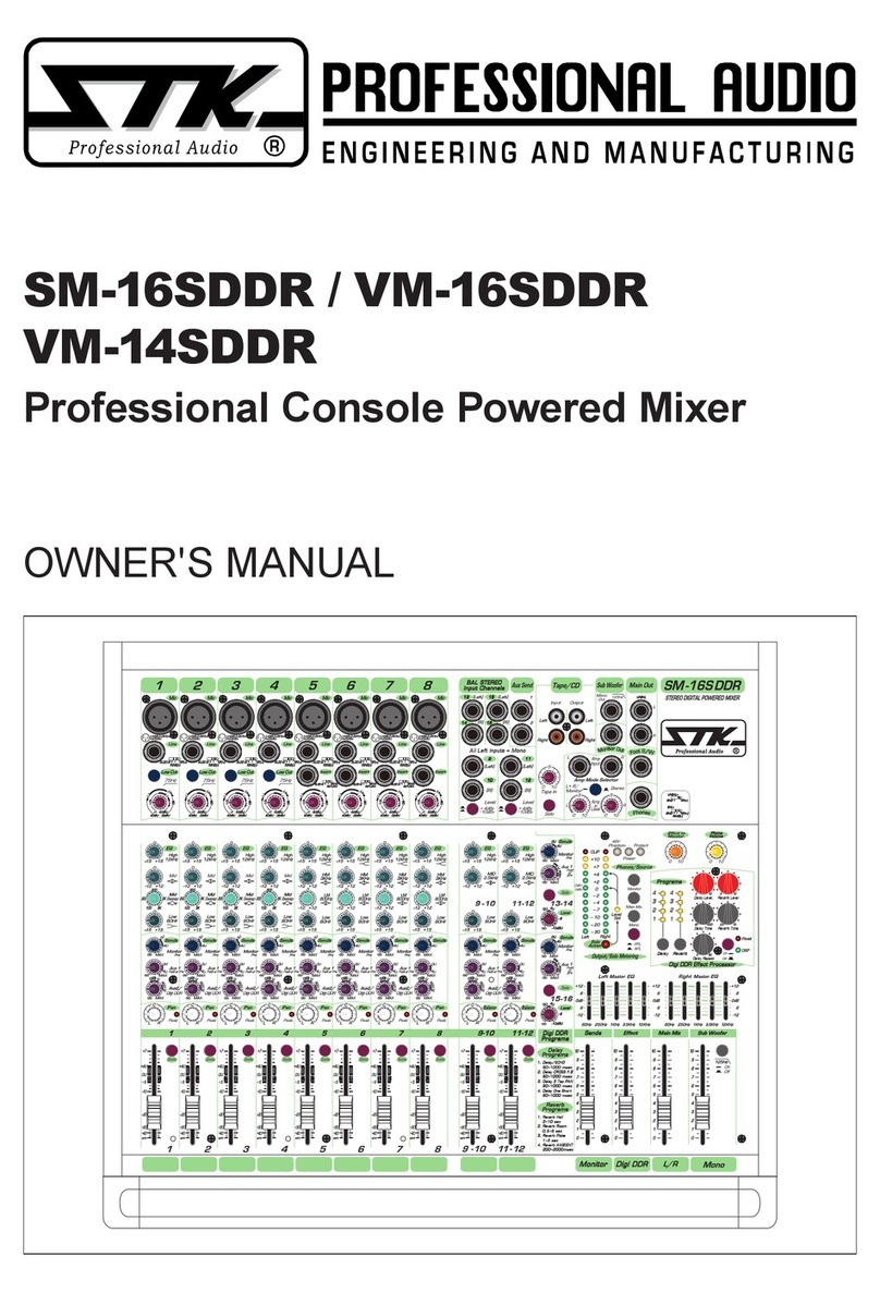
STK Professional Audio
STK Professional Audio SM-16SDDR User manual

STK Professional Audio
STK Professional Audio VM11T-DRV User manual
STK Professional Audio
STK Professional Audio CFX-2DDR User manual
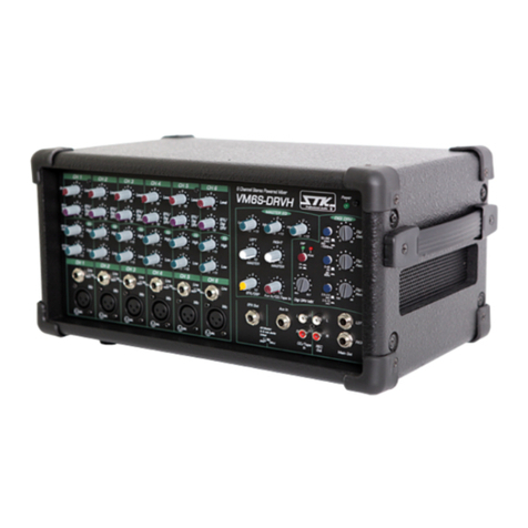
STK Professional Audio
STK Professional Audio VM6S-DRVH User manual
STK Professional Audio
STK Professional Audio VX1443-FDR User manual
STK Professional Audio
STK Professional Audio VM 6 User manual

STK Professional Audio
STK Professional Audio VX-804FXH User manual

STK Professional Audio
STK Professional Audio VM-11T DRV User manual
